Article

ADRC Control of Ultra-High-Speed Electric Air Compressor Considering Excitation Observation

1
School of Intelligent Manufacturing, Weifang University of Science and Technology, Weifang 262700, China
2
School of Automotive Engineering, Shandong Jiaotong University, Jinan 250357, China
3
School of Automobile, Chang’an University, Xi’an 710018, China
4
College of Mechanical and Vehicle Engineering, Chongqing University, Chongqing 400044, China
5
China Automotive Engineering Research Institute Co., Ltd., Chongqing 401122, China
6
Zhongtong Bus Co., Ltd., Liaocheng 252000, China
*
Author to whom correspondence should be addressed.
Actuators 2024, 13(10), 420; https://doi.org/10.3390/act13100420
Submission received: 31 August 2024 / Revised: 8 October 2024 / Accepted: 14 October 2024 / Published: 16 October 2024
(This article belongs to the Section Control Systems)

Abstract

:
With the increasing power of fuel cells, ultra-high-speed electric air compressors (UHSEACs) have been widely used. However, due to the ultra-high speeds involved, UHSEACs face problems such as long speed adjustment times and large speed fluctuations. Compared to other control methods, Active Disturbance Rejection Control (ADRC) is well-suited for highly nonlinear systems like UHSEACs. The Extended State Observer (ESO), a key component of the ADRC, struggles to accurately observe high-frequency excitations. To address this, the first step is to add a cascaded structure to the ESO and design a Current State Extended State Observer (CS-ESO) to better observe the electromagnetic and load excitations in the UHSEAC. The second step involves designing the ADRC based on the CS-ESO and performing speed adjustment simulations. The third step is to build a UHSEAC experimental platform and a conduct speed adjustment experiment. The findings indicate that, compared to the Proportional Integral Derivative (PID) control, the ADRC with the ESO, and the Sliding Mode Control (SMC), the use of the ADRC with the CS-ESO results in a significant reduction in overshoot—by at least 760 RPM under load-increasing conditions and 140 RPM under load-reducing conditions. Furthermore, the speed regulation time is notably decreased by at least 0.2 s and 0.1 s under these respective conditions.

1. Introduction

High power fuel cells demand quick response speeds in air supply [1]. Ultra-high-speed electric air compressors (UHSEACs) can rapidly adjust air output pressure and flow rate and can thus satisfy the dynamic requirements of fuel cells [2,3,4]. However, when the UHSEAC adjusts its speed to tens of thousands of revolutions per second, electromagnetic and load excitations increase, resulting in speed fluctuations. The elimination of fluctuations prolongs the speed adjustment time of the UHSEAC and restricts the power output response of the fuel cell [5].
The air compressor is driven by a motor, and feedback control can reduce the speed fluctuation of the motor by compensating for disturbances. Common feedback control methods for motors include PID [6], SMC [7], and ADRC [8]. Aiming at the water pump speed regulation system, Luo et al. [9] proposed a permanent magnet synchronous motor vector control method based on fuzzy PID. The characteristics of PID are a simple structure and convenient parameter adjustment. However, PID is sensitive to noise, which may cause overshoot and oscillation [10]. For the SMC to converge indefinitely, an adaptive strategy in fuzzy-based SMC (hybrid control technique) is developed to control the TRs in BLDC motor drives [7]. SMC exhibits low dependency on system and disturbance models [7,11]. However, due to the inertia effect, SMC exhibits the chattering phenomenon near the sliding surface. [12,13]. Liu et al. [14] proposed a novel improved permanent magnet synchronous motor automatic disturbance rejection control (ADRC) design based on an improved memetic algorithm. ADRC treats all uncertainties as unknown disturbances and utilizes input–output data to compensate for these disturbances [15]. It effectively addresses both internal and external unknown disturbances [16,17,18].
The Active Disturbance Rejection Control (ADRC) framework comprises a tracking differentiator, an Extended State Observer (ESO), and nonlinear state error feedback. Among these components, the ESO is identified as the most critical element. The core idea is to extend the total disturbance to a certain state of the system [19,20,21,22]. Liu et al. [23] designed an improved extended state observer using nonlinear functions, which can reduce noise in permanent magnet synchronous motor speed control systems. Wei et al. [24], through the design of an ESO with predetermined decreasing gains, reduced observation noise during the system’s steady state. Liu et al. [25] proposed an adaptive parameter adjustment algorithm based on offline Q-learning for the ESO, enhancing observation accuracy during system dynamics. In previous studies by scholars, the perturbation frequency of the system is lower than that of the USHEAC. It becomes challenging to continue to use ESO to select parameters and establish convergence results in a USHEAC’s observation tasks. By citing the CS-ESO mentioned in the literature [25,26], ADRC is improved. The CS-ESO can flexibly replace the nonlinear gain function to minimize the impact of noise on the observation results. The overall framework diagram of the paper is shown in Figure 1.
The innovation illustrated in this paper is as follows:
(1)
This paper innovatively proposes a method for stable control of the USHEAC by accurately observing electromagnetic excitation and load excitation. In order to solve the problem of difficulty in accurately observing electromagnetic and load excitation, a cascade connection is added to the original ESO, so that high-frequency electromagnetic and load excitation can be accurately observed.
(2)
ESO is the most important component of the ADRC for the speed fluctuation caused by electromagnetic excitation and load excitation at ultra-high speed. The optimized current state extended state observer (CS-ESO) is used to replace the extended state observer (ESO) in the ADRC system. The newly designed ADRC (CS-ESO) significantly alleviates the speed fluctuation of the UHSEAC and speeds up the speed regulation process.

2. UHSEAC Excitation Observation

2.1. UHSEAC Model Establishment

The UHSEAC can be compared to the following nonlinear system:
z ˙ = f 0 ( x , z , τ ) x ˙ = A x + B [ f ( x , z , τ ) + b u ] y = C x
where, x = [x1…, xn] TRn and zRp are state variables, τR is the external interference, uR is the control input, yR is the measurement output, b is the bounded uncertain non-zero control gain, f0: Rn × Rp × RRp and f: Rn × Rp × RR is an unknown continuous differentiable function.
The UHSEAC current loop model is:
d i q d t = u q R i q ω r i d L d + ψ r ω r L q
where, Ld is the d-axis inductance, H; Lq is the q-axis inductance, H; ψr is the rotor flux linkage, Wb.
The UHSEAC speed loop model is:
d ω r d t = n p ψ r i q + n p L d L q i d i q J + T L + f m ( ω m ) + f l ( ω l ) B ω r J
where, B is the friction coefficient; fm(ωm) is the electromagnetic excitation, and N·m; fl(ωl) is the load excitation, N·m. The main parameters of the UHSEAC studied in this article are shown in Table 1.

2.2. Theoretical Derivation of CS-ESO

Considering that ESO cannot accurately observe the electromagnetic and load excitation of the UHSEAC, the following text improves the ESO and derives CS-ESO. For Formula (1), let xn+1 = f(x, z, τ) + (bb0) u be the expansion state, where b0 is the bounded non-zero nominal value of the control gain b. The ESO can be designed as:
x ^ ˙ i = x ^ i + 1 + ε n 1 g i ( x 1 x ^ 1 ε n ) , 1 i n 1 x ^ ˙ n = x ^ n + 1 + g n ( x 1 x ^ 1 ε n ) + b 0 u x ^ ˙ n + 1 = ε 1 g n + 1 ( x 1 x ^ 1 ε n )
where, [ x ^ 1…, x ^ n+1] TRn+1 is the observation state; ε < 1 is a positive constant; gi: RR, 1 ≤ in + 1 is a continuous odd function.
It is worth noting that the ESO (4) has several shortcomings: (1) there are a lack of flexible solutions to apply different nonlinear gain functions gi(.), 1 ≤ in + 1; (2) when implemented in the feedback loop, the actual control gain b and the nominal control gain b0 must satisfy the matching condition of ∣(bb0)/b0∣ ≤ Δ0, where 0 < Δ0 < 1. Based on these observations, we propose the CS-ESO for Formula (1) [26]:
z ˙ 1 = g 1 ( e 1 ) ε , e 1 = y z 1 , x ^ 2 = g 1 ( e 1 ) ε z ˙ i = g i ( e i ) ε , e i = x ^ i z i , x ^ i + 1 = g i ( e i ) ε , 2 i n 1 z ˙ n = g n ( e n ) ε + b 0 u , e n = x ^ n z n , x ^ i + 1 = g i ( e i ) ε
where, z = [z1, z2…, zn]TRn is the observation state; ε < 1 is a positive constant; and gi: RR, 1 ≤ in + 1 is a continuous function.
In the speed regulation process of the UHSEAC, the speed needs to be adjusted to tens of thousands or even hundreds of thousands of revolutions in a short period of time, resulting in excessive overshoot and a peak effect. To overcome peaking effects, the proposed CS-ESO with saturation function is given by [26]:
z ˙ 1 = g 1 ( e 1 ) ε , e 1 = y z 1 , x ^ 2 = g 1 ( e 1 ) ε z ˙ i = g i ( e i ) ε , e i = x ^ i z i , x ^ i + 1 = g i ( e i ) ε , 2 i n 1 z ˙ n = g n ( e n ) ε + b 0 u , e n = x ^ n z n x ^ j + 1 = M j s a t g j ( e j ) M j ε , 1 j n
where, Mj > supt∈[0, ∞)xj+1(t)∣ is the saturation boundary and sat(.) is standard by sat(v) = sign(v)*min {1, ∣v∣} saturation function.
Let xq1 = iq, xq2 = f1, assuming that the derivative a(t) of f1 exists and is bounded, according to Formula (2) and Formula (1), the current loop observation state formula is as follows:
x ˙ q 1 = x q 2 + b 1 u q x ˙ q 2 = a ( t ) y 1 = x q 1
where, b1 is the current loop control gain; xq1 is the q-axis current state quantity, A; and xq2 is the q-axis current change rate, A/s.
Bringing the state variables xq1 and xq2 in Formula (7) into Formula (5), the second-stage CS-ESO of the UHSEAC current loop is obtained:
z ˙ q 1 = g 1 ( e q 1 ) ε + b 1 u q , e q 1 = y 1 z q 1 , x ^ q 2 = g 1 ( e q 1 ) ε z ˙ q 2 = g 2 ( e q 2 ) ε , e q 2 = x ^ q 2 z q 2 y 1 = x q 1
where, eq1 and eq2 are the observation errors of the q-axis current and the q-axis current change rate, respectively; zq1 is the q-axis current observation value; and zq2 is the q-axis current change rate observation value.
During the regulation process of the UHSEAC, the UHSEAC controller converts the speed regulation instructions into the d and q-axis current control targets. The d and q-axis currents are generally based on the maximum torque current ratio method [27] and the maximum torque to voltage ratio method [28]. The inverter continuously switches at high speed to convert the d and q-axis currents into a, b, and c three-phase currents, which results in the generation of d and q-axis currents. The electromagnetic excitation expression of the UHSEAC is:
f m ( ω m ) = n p ψ r 0 z q 2 d t + n p L d L q i d 0 z q 2 d t
where np is the number of electrodes. Integrate zq2 over time t to obtain the change in q-axis current Δq, and substitute it into Formula (9) to obtain the electromagnetic excitation of the UHSEAC.
Let xs1 = ω, xq2 = f2, assume that the derivative a(t) of f2 exists and is bounded, and transform Formula (3) into the speed loop observation state formula:
x ˙ s 1 = f 2 + b 2 i q x ˙ s 2 = h ( t ) y 2 = x s 1
where b2 is the speed loop control gain; xs1 is the speed of the UHSEAC, r/min; and xs2 is the total excitation of the speed loop, N·m.
Bringing the state variables xs1 and xs2 in Formula (10) into Formula (5), the second-stage CS-ESO of the UHSEAC speed ring is obtained:
z ˙ s 1 = g 1 ( e s 1 ) ε + b 2 i q , e s 1 = y ω z s 1 , x ^ s 2 = g 1 ( e s 1 ) ε z ˙ s 2 = g 2 ( e s 2 ) ε , e s 2 = x ^ s 2 z s 2 y ω = x s 1
where es1 and es2 are the observation errors of speed and total excitation, respectively; zs1 is the observed speed, r/min; and zs2 is the observed value of total excitation f2(t), N·m.
Electromagnetic excitation and load excitation act on the drive side and load side of the ultra-high-speed electric air compressor, respectively, and jointly exert influence on the ultra-high-speed electric air compressor. However, the cascade-expansion state observation method can only take the sum of all excitations affecting the system output as the total excitation. Therefore, it is necessary to separate the electromagnetic excitation from the load excitation and from the total excitation. Subtract the electromagnetic excitation f1(t) and the total excitation f2(t) and obtain the load excitation f3(t) expression of the UHSEAC as follows:
f 3 ( t ) = 1 2 π 0 F 3 ( ω ) e i ω t d ω

2.3. Analysis of Observation Results of Electromagnetic Excitation and Load Excitation

To validate the designed CS-ESO, the electromagnetic and load excitations of the UHSEAC were compared with the analytical values from the simulation model. Five working conditions were analyzed: idle (30,000 rpm), on/off blowing (35,000 rpm), rated speed (80,000 rpm), acceleration (70,000–90,000 rpm), and deceleration (90,000–70,000 rpm).
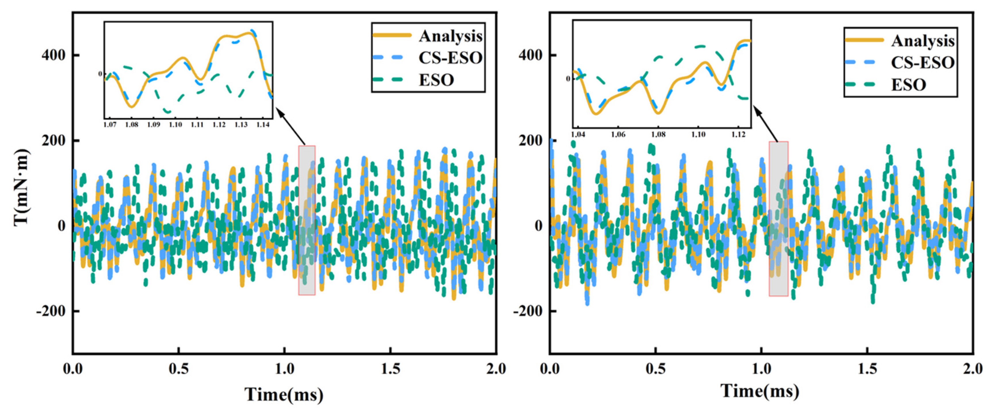
As shown in Figure 2, the electromagnetic excitation analytical values fluctuated between −80 mN·m and 80 mN·m during idling, with an average tracking error ratio of 1.6%. During on/off blowing, the analytical values fluctuated between −90 mN·m and 90 mN·m, with an average tracking error ratio of 2.3%. Under rated speed conditions, the analytical values fluctuated between −150 mN·m and 150 mN·m, with an average tracking error ratio of 2.9%.
As shown in Figure 3, during a speed increase, the electromagnetic excitation fluctuation amplitude of the UHSEAC changed from −120 mN·m to 120 mN·m to −180 mN·m to 180 mN·m when the speed rose from 70,000 rpm to 90,000 rpm, with an average tracking error ratio of 2.6%. Conversely, during deceleration, as speed reduced from 90,000 rpm to 70,000 rpm, the electromagnetic excitation fluctuation amplitude of the UHSEAC changed from −180 mN·m to 180 mN·m to −120 mN·m to 120 mN·m, with an average tracking error ratio of 2.9%.
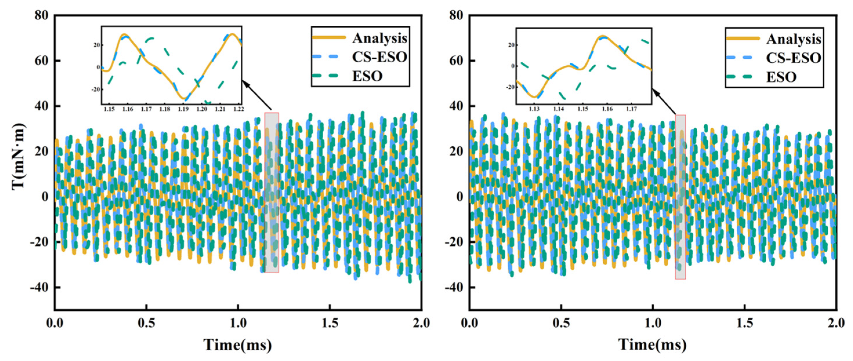
As shown in Figure 4, the load excitation analytical values fluctuated between −8 mN·m and 8 mN·m during idling, with an average tracking error ratio of 2.0%. During on/off blowing, the analytical values fluctuated between −10 mN·m and 10 mN·m, with an average tracking error ratio of 2.0%. Under rated speed conditions, the analytical values fluctuated between −32 mN·m and 32 mN·m, with an average tracking error ratio of 2.5%.
As shown in Figure 5, during a speed increase from 70,000 rpm to 90,000 rpm, load excitation analytical values fluctuated between −28 mN·m and 28 mN·m to −37 mN·m and 37 mN·m at 1.082 ms, with an average tracking error ratio of 2.8%. Under deceleration conditions, as the speed decreased from 90,000 rpm to 70,000 rpm, the load excitation fluctuation amplitude changed from −37 mN·m to 37 mN·m to −28 mN·m to 28 mN·m, with an average tracking error ratio of 2.3%.
By comparing the observation performance of the ESO and the CS-ESO, Figure 2, Figure 3, Figure 4 and Figure 5 show that the CS-ESO can track high-frequency excitation better, but the ESO cannot keep up with the changing speed of high-frequency excitation, showing observation delays and large observation deviations.

3. ADRC Design and Analyze Review

3.1. ADRC Design

The function of the tracking differentiator is to arrange the transition process based on the bearing capacity of the controlled object, obtain a smooth input signal, and provide the derivative of each order of the transition process [29,30].
The tracking differentiator can be designed to satisfy the following form:
x ˙ 1 = x 2 x ˙ 2 = r 2 f ( x 1 v ( t ) , x 2 r )
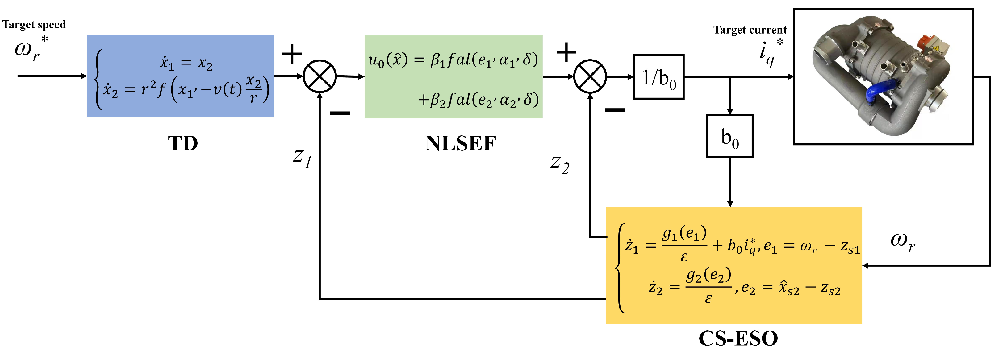
where r is the convergence speed of the system. The ESO uses the CS-ESO designed above. Nonlinear state error feedback is a nonlinear combination of errors between the various derivatives generated by the tracking differentiator and the observed values of state variables generated by the ESO [31]. Based on the output of the CS-ESO, the nonlinear state error feedback control law can be designed as:
u = 1 b 0 ( u 0 ( x ^ ) x ^ n + 1 )
where x ^ n+1 is used to compensate for the total uncertainty in real-time and u0(.) is used to ensure the stability and performance of the cascaded integrator system, u0(.) can be designed as follows:
u 0 ( x ^ ) = β 1 f a l ( e 1 , α 1 , δ ) + β 2 f a l ( e 2 , α 2 , δ )
where β1 and β2 are control gains; e1 and e2 are feedback state error; and 0 < α1 < 1 < α2, δ > 0. The ADRC structure designed in this article is shown in Figure 6.
This article uses PID, ADRC (CS-ESO), ADRC (ESO) and SMC for comparison. The principle of adjusting the ADRC parameters is as follows: When β1 is too large, it may cause oscillation or even divergence. If β2 is too small, it may cause divergence, whereas if it is too large, it may produce a high-frequency noise. During the parameter tuning process, the first step is to determine α the selection is a fixed parameter of 0.9, δ the selection is 0.01. Then, based on the trend of changes in the output image, adjust β1 and β2 reasonably. Initial value setting: Provide a reasonable initial value range for each parameter. For example, β1 and β2 usually start from a small value (such as a few hundred), and then gradually increase to observe the response of the system. Gradual adjustment: Use a step-by-step adjustment method, that is, first fix other parameters, adjust only one parameter, and observe the system performance (such as overshoot and adjustment time). Then gradually adjust other parameters. Observe the system response curve: Judge the quality of the parameters by observing the system’s overshoot, response time, stability, and other indicators. Some classic indicators of the control system, such as steady-state error, response time, and oscillation, can be combined to assist in adjustment. The three main parameters of a PID controller include proportional (Kp), integral (Ki), and derivative (Kd), each of which has a different impact on the system’s response. This article uses the trial-and-error method for parameter tuning, which adjusts in the order of “proportion first, integration second, and differentiation last”. During the adjustment process, observe the response curve of the system and gradually optimize the parameters until a satisfactory performance is achieved. C is the quality factor, and the larger the C, the faster the adjustment speed, but the more it is prone to overshoot. Q is the coefficient of the exponential convergence term. The higher the Q value, the faster the adjustment speed, but the more likely it is to experience overshoot. Mu is the coefficient of the constant velocity approach term. The higher Mu, the faster the adjustment speed, but the more prone it is to chattering.

3.2. ADRC Analysis

Respectively for the UHSEAC idling condition (n = 30,000 rpm), on/off blowing condition (n = 35,000 rpm), rated speed working condition (n = 80,000 rpm), load-increasing condition (n = 70,000 rpm–90,000 rpm), and five common working conditions of load-reducing condition (n = 90,000 rpm–70,000 rpm) were simulated and analyzed. The main parameters of the UHSEAC studied in this article are shown in Table 1.
As shown in Figure 7, the UHSEAC performed constant speed simulation: (a) The PID speed fluctuation range at idle speed was −100 rpm to 100 rpm. The ADRC (CS-ESO) was −50 rpm to 50 rpm. The ADRC (ESO) was −65 rpm to 65 rpm. The SMC was −85 rpm to 70 rpm. (b)—Under the air blowing on/off condition, the PID speed fluctuation range was −125 rpm to 100 rpm. The ADRC (CS-ESO) was −75 rpm to 50 rpm. The ADRC (ESO) was −85 rpm to 75 rpm. The SMC was −100 rpm to 100 rpm. (c) Under rated speed conditions, the PID speed fluctuation range was −250 rpm to 390 rpm. The ADRC (CS-ESO) was −80 rpm to 75 rpm. The ADRC (ESO) was −100 rpm to 120 rpm. The SMC was −180 rpm to 175 rpm.
As shown in Figure 8a, with load-increasing, fluctuations occurred at 0.50 s and 1.15 s, and the PID took a total of 1.80 s to reach 90,000 rpm, with an overshoot of 540 rpm. The ADRC (CS-ESO) took 1.45 s to reach 90,000 rpm, with an overshoot of 100 rpm. The ADRC (ESO) took 1.55 s to reach 90,000 rpm, and the overshoot was 180 rpm. The SCM took 1.67 s to reach 90,000 rpm, and the overshoot was 225 rpm. The speed adjustment time of the ADRC (CS-ESO) was reduced by 0.35 s, 0.1 s and 0.22 s, respectively. The overshoot was reduced by 440 rpm, 80 rpm and 125 rpm, respectively.
As shown in Figure 8b, with the load-reducing, fluctuations occurred at 0.50 s and 1.15 s, and the PID took a total of 1.65 s to reach 30,000 rpm, with an overshoot of 120 rpm. The ADRC (CS-ESO) took 1.5 s to reach 90,000 rpm, with an overshoot of 40 rpm. The ADRC (ESO) took 1.53 s to reach 30,000 rpm, and the overshoot was 70 rpm. The SCM took 1.58 s to reach 30,000 rpm, and the overshoot was 95 rpm. The speed adjustment time of the ADRC (CS-ESO) was reduced by 0.15 s, 0.03 s and 0.08 s, respectively. The overshoot was reduced by 80 rpm, 30 rpm, and 55 rpm, respectively.
By analyzing Figure 8, it can be seen that the speed adjustment time of the ADRC (CS-ESO) was shorter than that of the ADRC (ESO), PID, and SMC, regardless of the speed-up or speed-down conditions. Through the CS-ESO added to the ADRC, system disturbances, especially electromagnetic excitation and load excitation, could be observed. This made the ADRC show a superior speed regulation time and a smaller overshoot. The controller parameters of the simulation are in Table 2.

4. ADRC Experiment of UHSEAC

To assess the ADRC’s reliability, a fuel cell comprehensive control experimental platform was established based on the fuel cell performance experimental bench. This experiment was conducted using the fuel cell comprehensive control experimental platform, as depicted in Figure 9.
Experimental conditions: Ambient 20 °C, 60% humidity, 100 kPa air pressure. Load increase condition: Under this condition, the speed of UHSEAC gradually increased from idle speed (30,000 rpm) to rated speed (80,000 rpm). Load reduction condition: Under this condition, the speed of UHSEAC gradually decreased from rated speed (80,000 rpm) to idle speed (30,000 rpm). The speed was recorded, the changes were loaded and the controller response of the system during the load increase was processed, including the accuracy of the disturbance estimation, the stability of speed control, and the transient response of the system. After the speed of the UHSEAC increased from idle speed to rated speed, it remained at the rated speed for 5 s, then began to decelerate, changed from rated speed back to idle speed, and then remained at idle speed for 5 s. This was a cycle condition, and the cycle condition was performed 10 times in succession to obtain the experimental data. The main parameters of the experiment are shown in Table 3.
The specific equipment was as follows: (1) a hydrogen cylinder array, which provided hydrogen for fuel cells; (2) a nitrogen cylinder array, which provided nitrogen for fuel cell purging; (3) a high voltage power supply, which provided electrical energy for components such as the fuel cell cooling subsystem accessories and the upper computer; (4) an electronic load, which consumed the electrical energy generated by the fuel cells; (5) a water storage tank, which stored the coolant and, if necessary, replenished the coolant in the cooling subsystem; (6) a pure water machine, which purified the coolant; (7) an upper computer, which saved and recorded the data collected by various sensors, and issued commands for the control of the hydrogen circulation pumps, air compressors, and cooling water tower fans. The controller parameters of experiment are in Table 4.
The experimental object of the fuel cell comprehensive control experimental platform was an UHSEAC controller, in which the inverter used a SiC-mosfet switching devices. The switching frequency of SiC-mosfet switching devices could reach 34,000 Hz, with characteristics such as high temperature resistance, lower conduction loss, higher operating frequency, and higher operating voltage. The parameters of the controller are shown in Table 4.
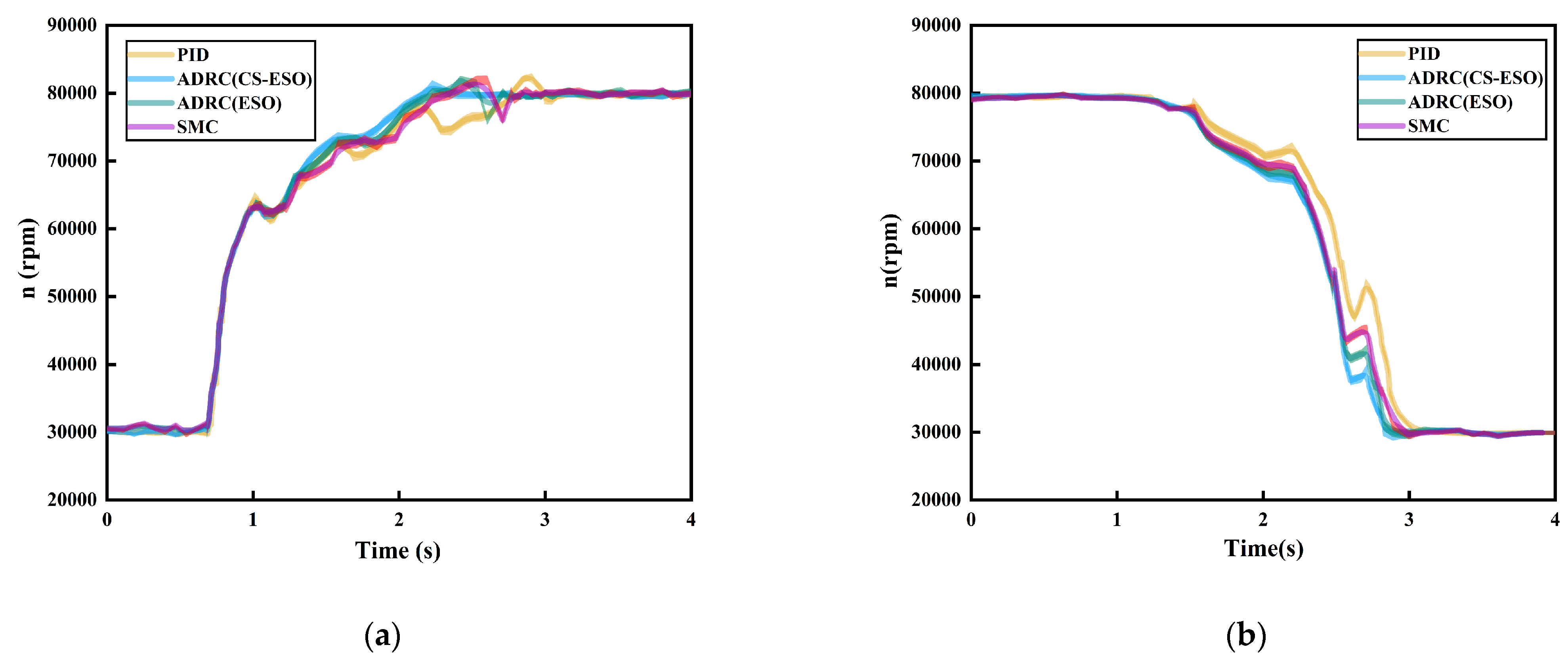
UHSEAC load-increasing experimental curve is shown in Figure 10a. Under PID, the overshoot was 2400 rpm at 2.9 s, reaching the rated speed (80,000 rpm) in 2.2 s. Under ADRC (CS-ESO), the overshoot was 1040 rpm at 2.2 s, reaching the rated speed (80,000 rpm) in 1.5 s. Under ADRC (ESO), the overshoot was 1800 rpm at 2.4 s, reaching rated speed (80,000 rpm) in 1.7 s. Under SMC, the overshoot was 1898 rpm at 2.5 s, reaching the rated speed (80,000 rpm) in 1.8 s. In comparison, the overshoot of the ADRC (CS-ESO) decreased by 1360 rpm, 760 rpm, and 858 rpm, respectively. The speed adjustment time of ADRC (CS-ESO) was 0.7 s, 0.2 s, and 0.3 s faster, respectively.
The UHSEAC load-reducing experimental curve is shown in Figure 10b. Under PID, the overshoot was 660 rpm at 3 s, reaching the idle speed (30,000 rpm) in 1.5 s. Under the ADRC (CS-ESO), the overshoot was 210 rpm at 2.8 s, reaching the idle speed (30,000 rpm) in 1.3 s. Under the ADRC (ESO), the overshoot was 350 rpm at 2.9 s, reaching the idle speed (30,000 rpm) at 1.4 s. Under the SMC, the overshoot was 460 rpm at 2.9 s, reaching the idle speed (30,000 rpm) at 1.4 s. In comparison, the overshoot of the ADRC (CS-ESO) decreased by 450 rpm, 140 rpm, and 250 rpm, respectively. The speed adjustment time of the ADRC (CS-ESO) was 0.2 s, 0.1 s, and 0.1 s faster, respectively.
Experimental data reveals the speed regulation response time of the ADRC (CS-ESO) was always optimal, whether it was increasing or decreasing the load, ensuring faster transitions between idle and rated speeds for the UHSEAC. The experimental results align with previous simulation analyses, confirming the designed ADRC’s effectiveness in meeting the UHSEAC’s speed regulation requirements.

5. Conclusions

This paper explored an active methodology for addressing load and electromagnetic excitation interference through the utilization of the current CS-ESO. The primary contributions of this research are as follows:
(1)
An ADRC (CS-ESO) was designed based on the improved CS-ESO. Simulation research shows that the maximum average tracking error ratio of electromagnetic excitation is 2.9%, and the maximum average tracking error ratio of load excitation is 2.8%, which proves the effectiveness of the designed the CS-ESO; compared with the PID, ADRC (ESO), and SMC, the ADRC (CS-ESO) has better adjustment under acceleration conditions, the speed adjustment time is 0.35 s, 0.1 s and 0.22 s faster, respectively. The speed adjustment time of the ADRC (CS-ESO) is 0.15 s, 0.03 s, and 0.08 s faster under the deceleration condition, proving the feasibility of the ADRC (CS-ESO) for speed regulation of the UHSEAC.
(2)
A comprehensive control experimental platform for fuel cell has been established. And an experimental scheme for UHSEAC self-disturbance rejection has been designed. The experimental results demonstrate this when compared with the PID, the ADRC (ESO) and the Sliding Mode Control (SMC), respectively. Under the increased load condition, the overshoot of the ADRC (CS-ESO) was reduced by 1360 rpm, 760 rpm, and 858 rpm, respectively, the speed adjustment time was shortened by 0.6 s, 0.2 s, and 0.3 s, respectively. Under the reduced load condition, the overshoot of the ADRC (CS-ESO) decreased by 450 rpm, 140 rpm, and 250 rpm, respectively. The speed adjustment time of the ADRC (CS-ESO) was 0.2 s, 0.1 s, and 0.1 s faster, respectively.
The method presented in this article has certain limitations. Specifically, numerous parameters within the ADRC approach require adjustment, including the selection of nonlinear functions, to adapt to varying systems and operational conditions. This process necessitates considerable time and effort for debugging and optimization. In actual industrial applications, these parameters may be difficult to determine in advance due to the complexity and variability of the environment and working conditions, and the adjustment process may consume a lot of time and resources. In actual applications, adaptive control strategies can be introduced to enable the system to automatically adjust the parameters of the CS-ESO according to the actual working conditions. Alternatively, online optimization techniques, such as parameter adjustment methods based on reinforcement learning or genetic algorithms, can be used to automatically optimize the control performance of the CS-ESO during actual operation.

Author Contributions

Conceptualization, J.Z. (Jiaming Zhou) and J.Z. (Jinming Zhang); methodology, Y.L. and F.Y.; software, J.Z. (Jiaming Zhou) and C.Z.; validation, J.Z. (Jinming Zhang), C.F., and C.Z.; formal analysis, C.Z. and B.D.; investigation, J.Z. (Jinming Zhang) and B.D.; resources, J.Z. (Jiaming Zhou); data curation, Y.L. and H.Q.; writing—original draft preparation, J.Z. (Jiaming Zhou); writing—review and editing, C.F. and F.Y.; visualization, H.Q. and Y.W.; supervision, Y.W., S.W.; project administration, J.Z. (Jiaming Zhou); funding acquisition, J.Z. (Jiaming Zhou). All authors have read and agreed to the published version of the manuscript.

Funding

This research was supported by Weifang University of Science and Technology High-level Talent Research Start-up Fund Project (Funding number: KJRC2023001; Funder: Jiaming Zhou); the 2023 Campus level Project of Weifang University of Science and Technology (Funding number: 2023KJ02; Funder: Jiaming Zhou. Funding number: 2023KJ03; Funder: Jinming Zhang); and the 2024 Weifang City Science and Technology Development Plan Projects (College and University Section) (Funding number: 2024GX031; Funder: Jiaming Zhou).

Data Availability Statement

The data presented in this study are available on request from the corresponding author due to data is part of ongoing research.

Conflicts of Interest

The authors declare no conflicts of interest. Author Bo Deng was employed by China Automotive Engineering Research Institute Co., Ltd. Author Honglei Qi was employed by Zhongtong Bus Co., Ltd.

References

  1. Ferrara, A.; Jakubek, S.; Hametner, C. Cost-optimal design and energy management of fuel cell electric trucks. Int. J. Hydrogen Energy 2023, 48, 16420–16434. [Google Scholar] [CrossRef]
  2. Jia, C.; He, H.; Zhou, J.; Li, K.; Li, J.; Wei, Z. A performance degradation prediction model for PEMFC based on bi-directional long short-term memory and multi-head self-attention mechanism. Int. J. Hydrogen Energy 2024, 60, 133–146. [Google Scholar] [CrossRef]
  3. Li, Y.; Wang, X.; Chen, S.; Lu, H. Nonlinear dynamic response and global stability of an air compressor vibration system. J. Low Freq. Noise Vib. Act. Control 2019, 38, 1081–1095. [Google Scholar] [CrossRef]
  4. Jia, C.; Liu, W.; He, H.; Chau, K.T. Deep reinforcement learning-based energy management strategy for fuel cell buses integrating future road information and cabin comfort control. Energy Convers. Manag. 2024, 321, 119032. [Google Scholar] [CrossRef]
  5. Su, Q.; Zhou, J.; Yi, F.; Hu, D.; Lu, D.; Wu, G.; Zhang, C.; Deng, B.; Cao, D. An intelligent control method for PEMFC air supply subsystem to optimize dynamic response performance. Fuel 2024, 361, 130697. [Google Scholar] [CrossRef]
  6. Qi, R.; Zhang, G. Permanent Magnet Synchronous Motor Vector Control System Based on the Fuzzy PID Controller. In Proceedings of the 2018 3rd International Workshop on Materials Engineering and Computer Sciences (IWMECS 2018), Jinan, China, 27–28 January 2018; Atlantis Press: Amsterdam, The Netherlands, 2018; pp. 379–382. [Google Scholar]
  7. Senthilkumar, R.; Balamurugan, R. Adaptive Fuzzy-Based SMC for Controlling Torque Ripples in Brushless DC Motor Drive Applications. Cybern. Syst. 2023, 54, 1132–1153. [Google Scholar] [CrossRef]
  8. Yang, F.; Jiang, F.; Xu, Z.; Qiu, L.; Xu, B.; Zhang, Y.; Yang, K. Complex coefficient ADRCler for current harmonics suppression of IPMSM drives. IEEE Trans. Power Electron. 2022, 37, 10443–10454. [Google Scholar] [CrossRef]
  9. Luo, Y.; Jin, T.; Li, X.; Qin, X.; Han, Y. Research on Pump Speed Control System Based on Fuzzy PID. Mechanics 2023, 29, 225–234. [Google Scholar] [CrossRef]
  10. Zhang, X.; Chen, Z.; Liu, C.; Luo, G. Robust speed controller design of pmsm drives by a proportional resonant-based adrc. In Proceedings of the 2021 24th International Conference on Electrical Machines and Systems (ICEMS), Gyeongju, Republic of Korea, 31 October–3 November 2021; IEEE: Piscataway, NJ, USA, 2021; pp. 609–614. [Google Scholar]
  11. Li, X.; Liu, C.; Wu, S.; Chi, S.; Loh, P.C. Sliding-Mode flux-weakening control with only single current regulator for permanent magnet synchronous motor. IEEE Access 2019, 7, 131616–131626. [Google Scholar] [CrossRef]
  12. Du, H.; Chen, X.; Wen, G.; Yu, X.; Lu, J. Discrete-time fast terminal sliding mode control for permanent magnet linear motor. IEEE Trans. Ind. Electron. 2018, 65, 9916–9927. [Google Scholar] [CrossRef]
  13. Zhang, Z.; Wang, Z.; Wei, X.; Liang, Z.; Kennel, R.; Rodriguez, J. Space-vector-optimized predictive control for dual three-phase PMSM with quick current response. IEEE Trans. Power Electron. 2021, 37, 4453–4462. [Google Scholar] [CrossRef]
  14. Liu, G.; Xu, C.; Wang, L. Modified ADRC design of permanent magnet synchronous motor based on improved memetic algorithm. Sensors 2023, 23, 3621. [Google Scholar] [CrossRef] [PubMed]
  15. Aboelhassan, A.; Diab, A.M.; Galea, M.; Bozhko, S. Investigating electrical drive performance employing model predictive control and active disturbance rejection control algorithms. In Proceedings of the 2020 23rd International Conference on Electrical Machines and Systems (ICEMS), Hamamatsu, Japan, 24–27 November 2020; IEEE: Piscataway, NJ, USA, 2020; pp. 1379–1384. [Google Scholar]
  16. Huang, Y.; Xue, W. Active disturbance rejection control: Methodology and theoretical analysis. ISA Trans. 2014, 53, 963–976. [Google Scholar] [CrossRef] [PubMed]
  17. Du, Y.; Cao, W.; She, J. Analysis and design of active disturbance rejection control with an improved extended state observer for systems with measurement noise. IEEE Trans. Ind. Electron. 2022, 70, 855–865. [Google Scholar] [CrossRef]
  18. Zhu, X.; Shi, H.; Zhang, C.; Du, Y.; Xu, L.; Zhang, L. Speed Ripple Suppression of Permanent Magnet Hub Motor Based on ADRC With Observer Error Constraints. IEEE Trans. Ind. Electron. 2024. early access. [Google Scholar]
  19. Zhuo, S.; Gaillard, A.; Xu, L.; Bai, H.; Paire, D.; Gao, F. Enhanced robust control of a DC–DC converter for fuel cell application based on high-order extended state observer. IEEE Trans. Transp. Electrif. 2020, 6, 278–287. [Google Scholar] [CrossRef]
  20. Zhu, J.; Ge, Q.; Sun, P. Extended state observer-based sensorless control for high-speed maglev application in single-feeding mode and double-feeding mode. IEEE Trans. Transp. Electrif. 2021, 8, 1350–1361. [Google Scholar] [CrossRef]
  21. Zhang, T.; Xu, Z.; Gerada, C. A Nonlinear Extended State Observer for Sensorless IPMSM Drives with Optimized Gains. IEEE Trans. Ind. Appl. 2020, 56, 1485–1494. [Google Scholar] [CrossRef]
  22. Guo, B.; Bacha, S.; Alamir, M. A review on ADRC based PMSM control designs. In Proceedings of the IECON 2017-43rd annual Conference of the IEEE Industrial Electronics Society, Beijing, China, 29 October–1 November 2017; IEEE: Piscataway, NJ, USA, 2017; pp. 1747–1753. [Google Scholar]
  23. Liu, B. Speed control for permanent magnet synchronous motor based on an improved extended state observer. Adv. Mech. Eng. 2018, 10, 1687814017747663. [Google Scholar] [CrossRef]
  24. Wei, W.; Xue, W.; Li, D. On disturbance rejection in magnetic levitation. Control Eng. Pract. 2019, 82, 24–35. [Google Scholar] [CrossRef]
  25. Chen, Z.; Qin, B.; Sun, M.; Sun, Q. Q-learning-based parameters adaptive algorithm for active disturbance rejection control and its applicationto ship course control. Neurocomputing 2020, 408, 51–63. [Google Scholar] [CrossRef]
  26. Ran, M.; Li, J.; Xie, L. A new extended state observer for uncertain nonlinear systems. Automatica 2021, 131, 109772. [Google Scholar] [CrossRef]
  27. Ekanayake, S.; Dutta, R.; Rahman, M.F.; Xiao, D. Deep flux weakening control of a segmented interior permanent magnet synchronous motor with maximum torque per voltage control. In Proceedings of the IECON 2015-41st Annual Conference of the IEEE Industrial Electronics Society, Yokohama, Japan, 9–12 November 2015; IEEE: Piscataway, NJ, USA, 2015; pp. 004802–004807. [Google Scholar]
  28. Jin, D.; Zhang, H.; Zhu, S.; Wang, A.; Jiang, J. Two-vector predictive current control strategy based on maximum torque per ampere control for PMSMs. J. Power Electron. 2022, 22, 1313–1323. [Google Scholar] [CrossRef]
  29. Chen, Z.; Zong, X.; Tang, W.; Huang, D. Design of rapid exponential integral nonlinear tracking differentiator. Int. J. Control 2022, 95, 1759–1766. [Google Scholar] [CrossRef]
  30. He, K.; Dong, C.; Wang, Q. ADRC for Uncertain Nonlinear Systems with Sporadic Measurements. IEEE/CAA J. Act. Sin. 2022, 9, 893–906. [Google Scholar] [CrossRef]
  31. Lu, D.; Yi, F.; Hu, D.; Li, J.; Yang, Q.; Wang, J. Online optimization of energy management strategy for FCV control parameters considering dual power source lifespan decay synergy. Appl. Energy 2023, 348, 121516. [Google Scholar] [CrossRef]
Figure 1. Overall framework diagram of the paper.
Actuators 13 00420 g001
Figure 2. Comparison between electromagnetic excitation observation values and model analysis values under constant speed conditions.
Actuators 13 00420 g002
Figure 3. Comparison of electromagnetic excitation observed values and model analytical values under variable speed conditions.
Actuators 13 00420 g003
Figure 4. Comparison between load excitation observation values and model analysis values under constant speed conditions.
Actuators 13 00420 g004
Figure 5. Comparison of observed values of load excitation under variable speed operating conditions and model analytical values.
Actuators 13 00420 g005
Figure 6. ADRC structure diagram.
Actuators 13 00420 g006
Figure 7. UHSEAC constant speed conditions simulation curve: (a) idling condition; (b) on/off blowing condition; (c) rated speed working condition.
Actuators 13 00420 g007
Figure 8. (a) UHSEAC load-increasing simulation curve; (b) UHSEAC load-reducing simulation curve.
Actuators 13 00420 g008
Figure 9. Fuel cell comprehensive control experimental platform.
Actuators 13 00420 g009
Figure 10. (a) UHSEAC load-increasing experimental curve; (b) UHSEAC load-reducing experimental curve.
Actuators 13 00420 g010
Table 1. The main parameters of the UHSEAC.
ParametersValueUnit
Stator winding resistance, Rm98
d. q-axis inductance, L0.25mH
Rotor flux linkage, ψr58mWb
Rated speed, n080,000rpm
Number of pole pairs, np1
Table 2. Controller parameter of simulation.
MethodParameterIdling Condition & On/Off Blowing ConditionRated Speed Working ConditionLoad-Increasing & Load-Reducing
ADRC(CS-ESO)β1500053005450
β2103014501500
α0.90.90.9
δ0.010.010.01
ADRC(ESO)β1450048005150
β2130016501700
α0.90.90.9
δ0.010.010.01
PIDKp101315
Ki0.50.50.5
Kd000
SMCQ300350385
Mu200200200
C608396
Table 3. The main parameters of the experiment.
ParametersParametersUnit
Actuators 13 00420 i001TypePEMFC
ModelXC88
Power rating (kW)88
Peak power (kW)100
Actuators 13 00420 i002Rated rotation speed (r/min)80,000
Rated torque (Nm)2.0
Rated power (kW)22
Actuators 13 00420 i003rated current (A)65
input voltage (V)250–750
Switch frequency range (kHz)0~110
Table 4. Controller parameter of experiment.
MethodParameterLoad-Increasing & Load-Reducing
ADRC(CS-ESO)β15300
β21460
α0.9
δ0.01
ADRC(ESO)β14900
β21400
α0.9
δ0.01
PIDKp15
Ki0.5
Kd0
SMCQ380
Mu200
C92
Disclaimer/Publisher’s Note: The statements, opinions and data contained in all publications are solely those of the individual author(s) and contributor(s) and not of MDPI and/or the editor(s). MDPI and/or the editor(s) disclaim responsibility for any injury to people or property resulting from any ideas, methods, instructions or products referred to in the content.