1. Introduction
The Acquisition, Tracking and Pointing (ATP) system refers to a system that is capable of precisely controlling equipment or mechanisms to make minute adjustments or undertake positioning in a specified direction. It typically possesses features such as high-precision pointing, stable control, and rapid response. It has been widely applied in many manned and unmanned platforms for receiving and transmitting information with seeker devices such as antennas, IR/UV sensors, optical devices, etc. for reconnaissance, prewarning, guidance, communication, and other functions [
1,
2,
3]. The development of the new-generation ATP system has put forward higher requirements for pointing accuracy, servo bandwidth, compact structure, and lightweight design. Among them, the servo bandwidth represents the system’s ability to follow rapidly changing commands. However, nonlinear disturbances, such as friction, backlash, mass unbalance, and carrier disturbance, restrict further improvement of the performance of the ATP system. As a result, disturbance rejection performance becomes a key controller property for achieving high pointing and tracking accuracy.
Nonlinear disturbances can be roughly divided into two categories: time-invariant and time-varying disturbances. For time invariant disturbances, scholars have proposed various control algorithms, such as sliding-mode control [
4,
5,
6] and internal mode control [
7,
8]. They have been proven to be very useful in practical systems. However, for time-varying disturbances, such as friction, backlash, and carrier disturbance, it is difficult to effectively suppress them using the above controllers.
In order to suppress the nonlinear time-varying disturbances, scholars have conducted extensive research. The compensation methods can be mainly divided into two categories: disturbance-model-based and observer-based. The basic concept of a disturbance-model-based compensation method is to design accurate nonlinear disturbance models and then compensate them with a feed-forward compensator. Cong et al. [
9] designed an improved Stribeck friction model and acquired the parameters identified by a genetic algorithm. By optimizing the friction model, the chattering phenomenon and limit cycle caused by changes in the motion direction of the inertial stability platform and friction overcompensation were effectively improved. In a similar vein, Li et al. [
10] proposed a novel pre-stiction friction model which is a modified LuGre model, including the pre-sliding, the sliding and the pre-stiction regimes, that can characterize friction behaviors in the pre-stiction regime. Liao et al. [
11] proposed a new friction model of a harmonic gear servo system, which is related to both its velocity and position. The drawback of the disturbance-model-based compensation method is that it is difficult to construct a disturbance model with sufficient accuracy, especially when coupled with other random disturbances.
To address these disturbances without a specific structure, disturbance observers have been extensive studied. The most widely used ones include disturbance observer (DOB), Kalman filter, extended state observer (ESO), active disturbance rejection control (ADRC), generalized proportional integral observer (GPIO), etc. [
12,
13,
14,
15]. Although the disturbance-observer-based compensation methods mentioned above ensure that the estimated disturbances asymptotically follow the actual disturbance, its observation performance is weak when the disturbance is complex and has no specific structure. According to Li et al. [
7], disturbances without a specific structure can be considered as time-varying disturbances, which can be approximated by a finite-order time polynomial function, so the several orders derivatives of the disturbances can be considered as augmented states for simultaneous estimation. Therefore, the proportional multiple-integral (PMI) observer has been investigated for estimating such time-varying disturbances [
16,
17,
18,
19] and good compensation results have been achieved. On this basis, Jiang et al. [
20] fulfilled the PMI observer in the State-Augmented Kalman filter framework (PMISAKF). The PMISAKF observer is designed based on the time series polynomial function of time-varying disturbances. It can acquire a better disturbance estimation result and fully consider the measurement noise, process noise, and mobility characteristics of the estimated disturbance in the discrete system. Li et al. [
21] investigate the mapping relationship between internal and external disturbances and servo performance by establishing a high-precision dynamics model of the servo device. The control method is also a combination of a PI controller and PMISAKF. However, They directly compensate the disturbance observation values into the system, which can easily cause system instability during high-frequency or instantaneous disturbances.
In recent years, many scholars have conducted research on model predictive control (MPC) to address the time-varying, nonlinear, and uncertain characteristics of external disturbances. MPC can solve optimal control problems in a finite time domain without the need for precise models through time-domain rolling iterative optimization, enabling it to handle uncertainty problems caused by model mismatch and unknown disturbances [
22,
23,
24]. The disturbance observer-based technique is a promising method for improving the robustness of MPC by estimating and compensating disturbances simultaneously [
25]. Examples of disturbance observer-based MPC include [
26,
27]. Emami et al. [
26] developed an adaptive model-based predictive controller for attitude and trajectory tracking of a vertical take-off and landing aircraft, and two observers were introduced to simultaneously estimate the model uncertainty and external disturbance; additionally, time-varying trajectory tracking was carried out via simulation, and the experiment was not presented. Wang et al. [
27] presents an improved equivalent input disturbance observer-based model predictive control (IEIDO-based MPC) scheme for position tracking control of a magnetic levitation system. The IEIDO was first proposed to estimate both the system states and the time-varying equivalent input disturbance. It effectively demonstrates that MPC based on a disturbance observer has emerged as a promising strategy for enhancing the system’s capability in mitigating disturbances. It is crucial to note that, while the magnetic levitation system necessitates sub-millimeter servo accuracy, its applicability to the ATP system, which demands even higher tracking and pointing accuracy, remains an open question that warrants further validation.
The innovation of this paper lies in proposing a PMISAKF-MPC controller which significantly enhances the system’s capacity to counteract nonlinear and time-varying disturbances. Specifically, a PMISAKF is an algorithm that combines predictive modeling, incremental state-space representation, and adaptive Kalman filtering techniques. It utilizes the system’s dynamic model and observational data to estimate and track the system’s state and external disturbances in real-time through filtering and prediction steps. The disturbance estimates obtained through a PMISAKF can be regarded as known external inputs at the current or future time points. By incorporating time-varying disturbance information into the predictive model of MPC, the optimization process can take these external factors into account and compute the optimal control strategy accordingly. MPC continuously updates its control strategy through iterative optimization processes based on new observational data and disturbance estimates. This iterative nature allows MPC to flexibly address system uncertainties and external disturbances, achieving high tracking and pointing accuracy under nonlinear time-varying disturbances. Furthermore, it helps the MPC controller maintain system stability and performance in the presence of time-varying disturbances, enhancing the robustness and adaptability of the control.
This paper is organized as follows. A dual-inertia dynamics model of the system is developed and the disturbances are analyzed in
Section 2. Then, the PMISAKF-MPC strategy is described. In
Section 4, the results of the comparison experiments are analyzed.
Section 5 concludes this paper.
2. Dynamic Modeling
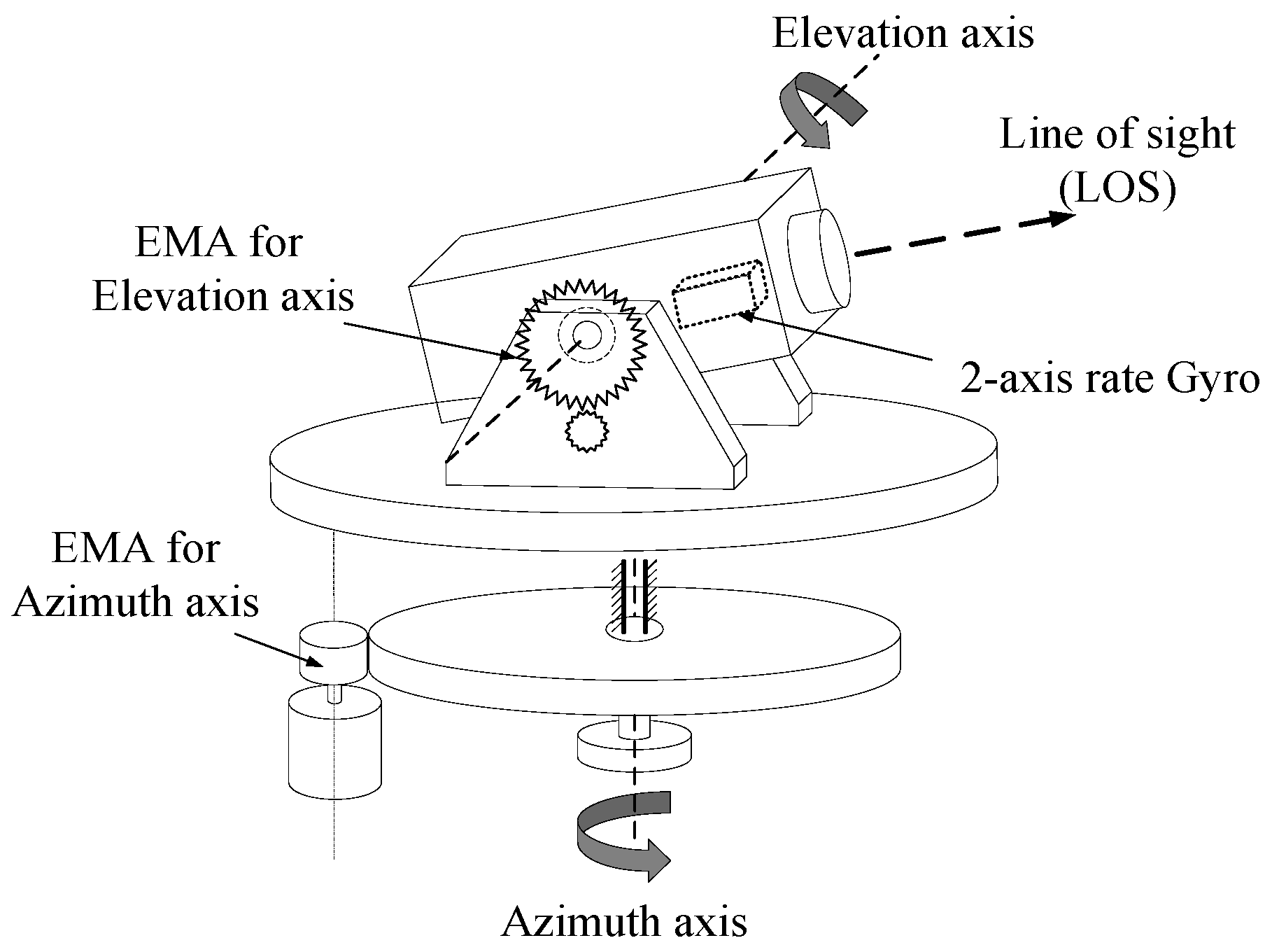
A high-precision ATP system is crucial for maintaining a stable line of sight (LOS) in inertial space. Its primary function is to isolate various multi-source disturbances, including friction, backlash, and carrier disturbance, ensuring that the LOS remains unperturbed and precisely aligned towards its intended target. The structure of a typical two-axis ATP system is shown in
Figure 1. The azimuth/elevation axis is derived by the electromechanical actuator (EMA), which is mainly composed of key components such as the driver controller, motor, reducer, encoder, and gear reducers.
The EMA usually adopts two driving methods, namely direct motor driving or indirect reducer driving. The direct motor driving method avoids the impact of transmission chain factors on servo performance by directly coupling the motor with the load. It can achieve good control accuracy and a working bandwidth, but this method requires a high output torque in the motor, which limits its application in situations where space size and weight requirements are strict. The indirect reducer driving method can reduce the volume and weight of the servo mechanism to a certain extent. However, this transmission method inevitably has nonlinear factors such as friction, backlash, etc. These nonlinear factors exist in the system in the form of disturbances. Along with external disturbances, it restricts the improvement of the servo performance of the ATP system. As a result, the disturbance rejection performance becomes a key controller property in achieving precise positioning, particularly in regard to the indirect reducer driving method.
2.1. Modeling of the ATP System
The ATP SYSTEM with an indirect reducer driving method usually consists of an AC servo motor, a gear reducer, and a load. Considering the elastic components of the transmission mechanism, we can use the dual-inertia model to represent it,
where,
are the angle and velocity of the AC servo motor,
are the angle and velocity of the load,
u is the motor voltage,
is the voltage conversion coefficient of the drive,
is the motor torque coefficient,
and
are the reduction ratio and stiffness of the gear reducer, respectively.
are the inertia of the motor and load, and
is the total disturbances torque. The established dual-inertia model of a single axis of an ATP system is shown in
Figure 2.
Among them, the nonlinear disturbances, such as friction, backlash, and carrier disturbance, restrict further improvements in the performance of the system. It is necessary to analyze the characteristics of each of them and find the appropriate method to solve them.
2.2. Disturbances Modeling
According to the Ref. [
17], the disturbances could be classified into two parts, namely the equivalent torque disturbance of friction,
, and carrier disturbance,
. They could be described as
where,
,
Mi and
fi are the number, amplitude, and frequency of frequency components, respectively.
is the viscous damping friction coefficient of the bearing,
is the total equivalent force borne by the bearing,
is the bearing gyration radius, and
is the equivalent relative rotation speed of the driven gear. Additionally,
is the constant meshing friction coefficient,
is the output torque of the motor, and
and
are the circle radius of the driven and driving gear, respectively.
is the displacement increment of the rotation center of the driving gear,
α represents the operating pressure angle.
We can divide the disturbance into two parts, namely time-invariable disturbances
and time-varying disturbances
. Equation (2) can be simplified as,
Time-invariant disturbances can be considered as a stepwise signal that can introduce steady-state errors to the servo system, while the time-varying disturbance is the combination of multiple periodic signals with unknown frequencies and magnitudes. It introduces dynamic errors to the LOS and may lead to system oscillation and dispersion.
3. PMISAKF-MPC Controller
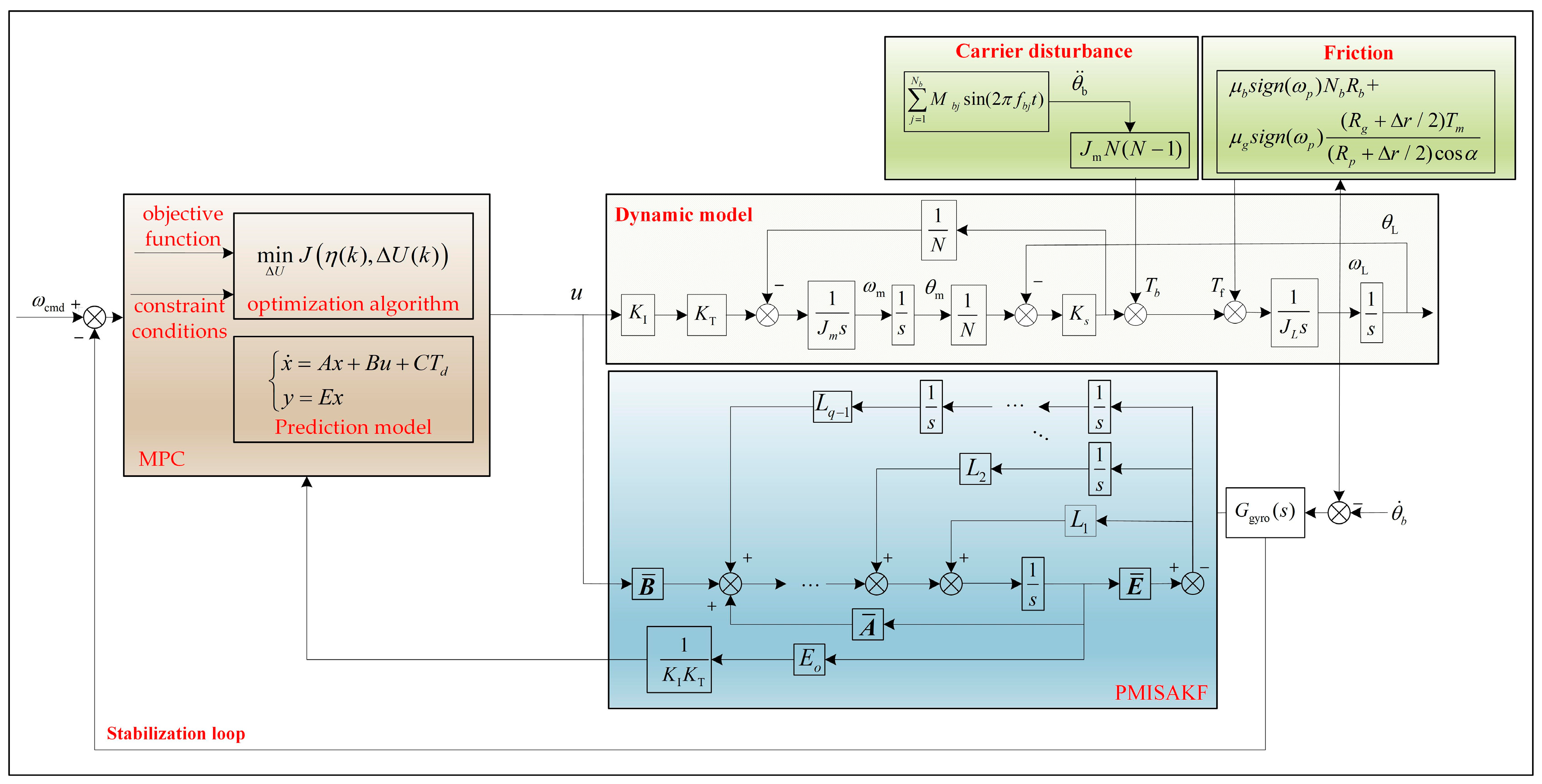
Based on the above analysis, a PMISAKF-MPC controller has been proposed. The structure of the proposed control algorithm is shown in
Figure 3. Specifically, the PMISAKF observer is used to estimate time-varying disturbances, and then the rolling iteration optimization mechanism of MPC is utilized to incorporate the obtained estimated time-varying disturbances to predict the optimal control output for the next time step. This enables the system to maintain LOS stability and precise tracking of commands under the influence of friction and carrier disturbances.
3.1. Design of PMISAKF Observer
It can be assumed that the time-varying disturbance
can be described by the following polynomial function:
where
are constant but unknown coefficients.
The q-order derivation of is bounded, so we can extend as the state for simultaneous estimation, and the PMISAKF observer compensates well for this type of disturbance.
In this section, a PMISAKF observer based on the dual-inertia model is proposed to estimate the time-varying disturbance
. Assuming that the time-invariable disturbance
is perfectly eliminated, recalling Equation (1), the following system can be obtained:
where,
Assuming that
can be approximated by the polynomial shown in Equation (4), the q-order derivative of the disturbance
is bounded. To track the time-varying disturbance, we introduce the following parameters:
where
is the
th-order derivative of
.
The PMISAKF observer used to obtain the estimates of velocity and disturbance for Equations (5) and (6) is proposed as follows:
where
and
are the estimated values of
and
, respectively. The observer gain
and the integral factors of the observer
are the parameters to be designed.
The estimate disturbance
can be expressed as:
If
, the PMISAKF observer used to estimate the defined state can be obtained by combining (7) and (8):
where
Similarly, Equation (9) can also be rewritten in the discrete-time domain with a zero order hold as:
The observation error of the system
can be expressed as
In Equation (5), pair
is observable, and the following equation holds:
Pair is observable. Therefore, the error model shown in Equation (11) is asymptotically stable after selecting an appropriate .
Based on the previously established dynamic model parameters, as well as noise and disturbance covariance values, the gain
of the observer can be computed offline iteratively by the following equation until convergence to the steady-state value is reached.
where
is the noise input matrix,
is the noise variance in the system process noise, including the noise variance in the control voltage and the noise variance in each order disturbance,
is the measured noise variance matrix of the angle and the velocity of the motor and the load,
is the covariance in the estimation error vector, and
is its prediction to the next iteration.
The values of can be obtained by calculating the noise variance in the encoder and the gyro, and is the analog output noise variance in the DA converter. are the variance in the observed disturbance.
can be obtained iteratively offline, and the converged steady-state values are applied to Equation (9) for the real-time estimation of
. The
estimated by the PMISAKF observer is converted into a voltage for compensating the time-varying disturbance
by Equation (14) and is provided to the MPC controller.
3.2. Design of MPC
MPC mainly consists of four parts: prediction model, objective function, constraint conditions, and optimization algorithm. If
, Equation (1) can be converted into the following state space equations:
where,
Equation (15) can be rewritten in the discrete-time domain with a zero order hold as:
where,
is the sample counter. The discrete process is shown in Equation (20).
where,
is the discrete time sampling period. Expanding the state vector to
, then Equation (16) can be rewritten as:
where
,
is the dimension of the control parameters, and
is the dimension of the state parameters.
and
are the variation in control output and disturbance from the previous moment to this moment, respectively.
If we set the prediction domain to
, the control domain to
, and
, then the future output predicted by the system can be deduced from Equation (18) as:
where,
Considering that the target of the system is to achieve accurate tracking of the velocity command without exceeding the maximum torque of the motor, the velocity-following residuals and control increments of the system are taken as the state quantities of the objective function. The objective function is then obtained as
where
is the velocity command,
indicates that the system output at
moment is used to predict the system output at
moment, where
.
is the increment of the system control at
moment, where
.
The system needs to constrain the motor voltage and its increments for the control input as follows:
where,
and
are the minimum and maximum values of motor voltage, respectively.
and
are the minimum and maximum values of motor voltage increments, respectively.
The problem of optimal solution of the objective function is to achieve the minimum of Equation (20) in the prediction domain under the condition that Equation (21) is satisfied. Let
, then Equation (20) can be transformed into a standard quadratic programming problem to be solved as
where,
. In the case where
is strictly positive definite, the objective function can be expressed as a quadratic curve of the independent variable
, whose minimum value can be solved by Equation (23), and the final result is shown in Equation (24).
The first term of the control input increment
is taken out to obtain the control input of the system at the current moment as:
4. Experimental Results
In order to test the effectiveness of the proposed algorithm, an experimental platform is constructed with an EMA as the control object, and a series of experiments are carried out.
4.1. Experimental Setup
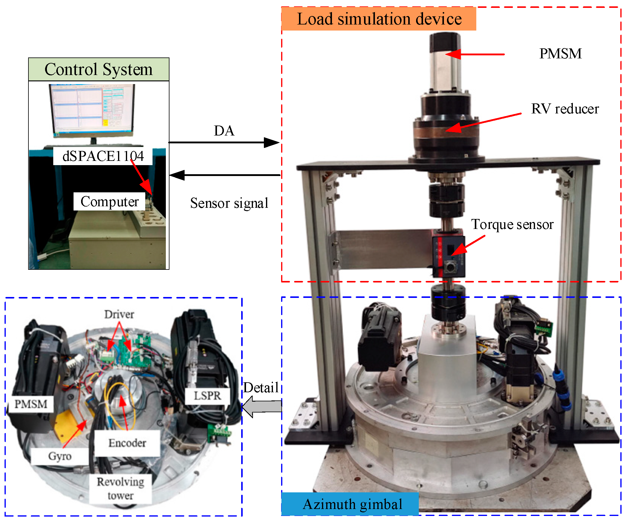
The experimental device has three components: a typical EMA, a load simulation device, and a dSPACE, as shown in
Figure 4. The EMA mainly consists of two PMSMs (China, PALKI, model: SPALY80), two drivers (Israel, Elmo, model: P/N: SOL-WHI 20/100PYE), two LSPRs (China, SKGR, model: FABR060-25-S2-P1), and an absolute encoder (China, Yingdong, model: CAPRO-B112050). The load simulation device consists of a permanent magnet synchronous motor (China, OTOI, model: ASM80B1007-30M), an RV reducer (China, Zhenkang, model: ZKRV-20E-161-B), and a torque sensor (China, Daysensor, model: DYN-200). A dSPACE system (Germany dSPACE, DS-1104) is utilized to decode the feedback signals and generate real-time codes for such a system. The sampling rate of the dspace system is 1000 Hz.
4.2. Control Parameters
According to the experimental device parameters, the values of the system state space model can be calculated as:
Considering that the control cycle of the servo system is set to T
s = 1 ms, the state-space model values in the discrete time domain with a zero-order hold are as follows:
Weighing the computing ability of the computer and the performance of the controller, we set . Then, the specific values of ,,,, , and of MPC can be calculated.
The control objective of MPC is to achieve fast and accurate responses to speed commands and efficient suppression of unknown disturbances. After extensive simulation verification and actual testing, it was found that the weights of the state variables and control variables are as follows:
. On the basis of the above values, the matrix of the standard quadratic programming problem is calculated as:
We can find that the matrix is strictly positive definite, so the solution of the objective function is reasonably calculated by Equations (23) and (24).
Next, we examine the parameter values of the PMISAKF observer. When , the computation of the PMISAKF observer increases sharply; thus, we let . Based on the parameters of the dual-inertia state space model of the system, ,,, and the discretized ,, for the PMISAKF observer can be calculated.
Thus, the variance in the control output signal and the velocity the encoder are:
Disturbance variances determine the pole locations of the PMISAKF observer and are directly related to the convergence velocity and the observation noise of the estimated disturbance. Generally, high values for the disturbance variance result in faster estimates but worse noise. The following values of
are proven helpful for a better response and tracking performance in the actual system.
Finally, the optimal gains of the PMISAKF observer are computed offline as follows:
4.3. Analysis of Experimental Results
A series of verification experiments are carried out on the experimental device shown in
Figure 4 to evaluate the effectiveness of the control algorithm proposed in this paper. The testing project includes a square tracking experiment, sine tracking experiment, and frequency domain response testing under no-load conditions. The disturbance torque simulation device is used to simulate the base coupling torque and temporary impact torque, and control performance testing is carried out under disturbance conditions. The compared methods include Method 1(PI), Method 2(PI+PMISAKF, proposed in the Ref. [
20]), and the proposed compound control algorithm (MPC+PMISAKF). The gains of PI can be obtained through pole assignment of the closed-loop system matrix; this process has been detailed in the Ref. [
20].
4.3.1. Verify the Effectiveness of the Disturbance Observer
To verify the effectiveness of the proposed PMISAKF observer based on the dual-inertia model, the disturbance observation accuracy of different observers is compared. The project consists of two categories: one is to input a sine signal speed command to observe the friction torque and the other is to apply base coupling disturbance torque to the model when the speed command is zero to observe the base coupling torque. Three types of disturbance observers have been designed: DOB, a PMISAKF observer based on the single-inertia model proposed in Ref. [
20], and a PMISAKF observer based on the dual-inertia model proposed in this paper.
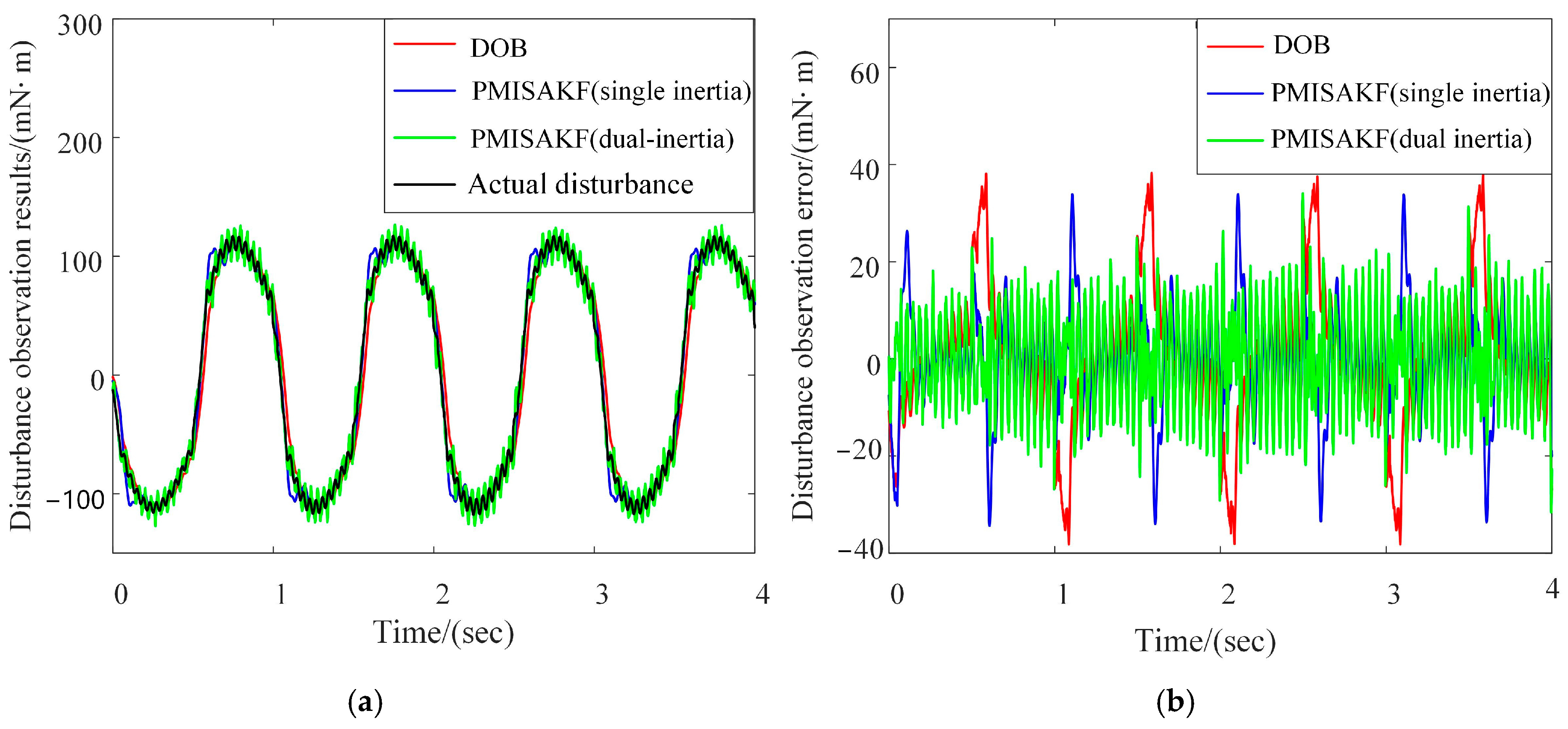
We can operate the system in a velocity closed-loop state and input a sinusoidal signal with an amplitude of 6.28 °/s and a frequency of 1 Hz as the command. Additionally, we can collect input and output shaft torque information through motor current sensors and torque sensors on the RV reducer output shaft and then subtract the input shaft torque value and the ratio of the output shaft torque to the transmission ratio as the actual friction torque value. We can then compare the observation effects of different observers on nonlinear friction torque. The results are shown in
Figure 5. The disturbance observation error represents the difference between the actual disturbance and the observation results. It can be found that the peak value has been significantly reduced using the proposed method. This indicates that this method can better characterize the zero crossing characteristics of friction disturbances.
Similarly, we can operate the system in a velocity closed-loop state, set the speed command to zero and add the carrier disturbance at the first second using the load simulation device. W e can then compare the observation effects of different observers, as shown in
Figure 6. It could also be found that the disturbance observation error in the proposed method is minimal. The reason is that the multiple integration link in the PMISAKF can accumulate observation errors multiple times, improving the observation accuracy of the PMISAKF. The nominal model for the PMISAKF proposed in this paper is a dual-inertia model, which is closer to the actual system compared to the single-inertia PMISAKF designed based on the first order link and can further improve observation accuracy. Accurate estimation of disturbances can reduce the number of iterations of MPC controllers, which provides convenience for the use of MPC in high dynamic applications.
4.3.2. Velocity Closed-Loop Time Response
A square signal with an amplitude of 6.28°/s and a frequency of 0.5 Hz is applied to the velocity command and the tracking residuals of the different control methods are compared. The experimental results show that the proposed method significantly improves the rapidity of the response while reducing the overshoot, as shown in
Figure 7. The velocity tracking residual represents the difference between velocity command and response.
The experiment results are summarized in
Table 1. Compared to Method 1, Method 2 reduces the adjustment time by 17.07%, but increases the overshoot by 116.28%. If the load is increased, the overshoot may further increase or even become unstable, which poses a safety hazard. When using the proposed method, not only can the adjustment time be reduced by 50.41% but the overshoot can be reduced by 17%. This indicates that the proposed method can significantly improve the dynamic response performance of the system.
A Sinusoidal signal with an amplitude of 6.28°/s and a frequency of 1 Hz is applied to the velocity command, and the tracking residuals of the different methods are compared. The experimental results are shown in
Figure 8, in which the red solid line is Method 1, the blue solid line is Method 2, and the green solid line is proposed method. The equivalent stabilization accuracy is the integration of the velocity tracking residual. We can find that the tracking residual of the proposed method is significantly reduced.
The experiment results are summarized in
Table 2. Compared to Method 1, Method 2 reduces the velocity-tracking residuals by 32.14% and the equivalent stabilization accuracy by 36.14%. The proposed method reduces the velocity-tracking residuals by 66.07% and the equivalent stabilization accuracy by 71.08%. The experimental results indicate that the proposed method can further improve the velocity-tracking performance.
4.3.3. Velocity Closed-Loop Frequency Response
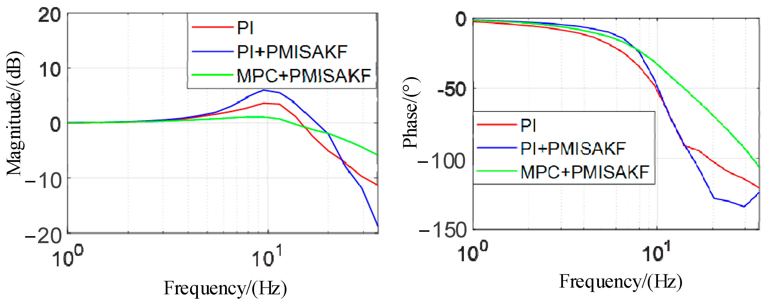
In the frequency domain, the velocity closed-loop frequency responses of the system at different control methods are compared, and the results are shown in
Figure 9. The system operates in a velocity closed-loop state with no external load applied. Using sine signals of different frequencies with an amplitude of 6.28°/s as velocity commands, the response at different frequencies is obtained through frequency sweeps and plotted into Bode plots. The comparison results show that the Method 2 has a higher bandwidth than Method 1 but also has a larger overshoot. The proposed method improves the closed-loop bandwidth while reducing overshoot. The experiment results are summarized in
Table 3. Compared to Method 1, Method 2 improves the response bandwidth by 29.41% from 17 Hz to 22 Hz. The proposed method improves the response bandwidth by 41.18% to 24 Hz. This indicates that the system’s ability to resist external disturbances has increased.
4.3.4. Carrier Disturbance Test
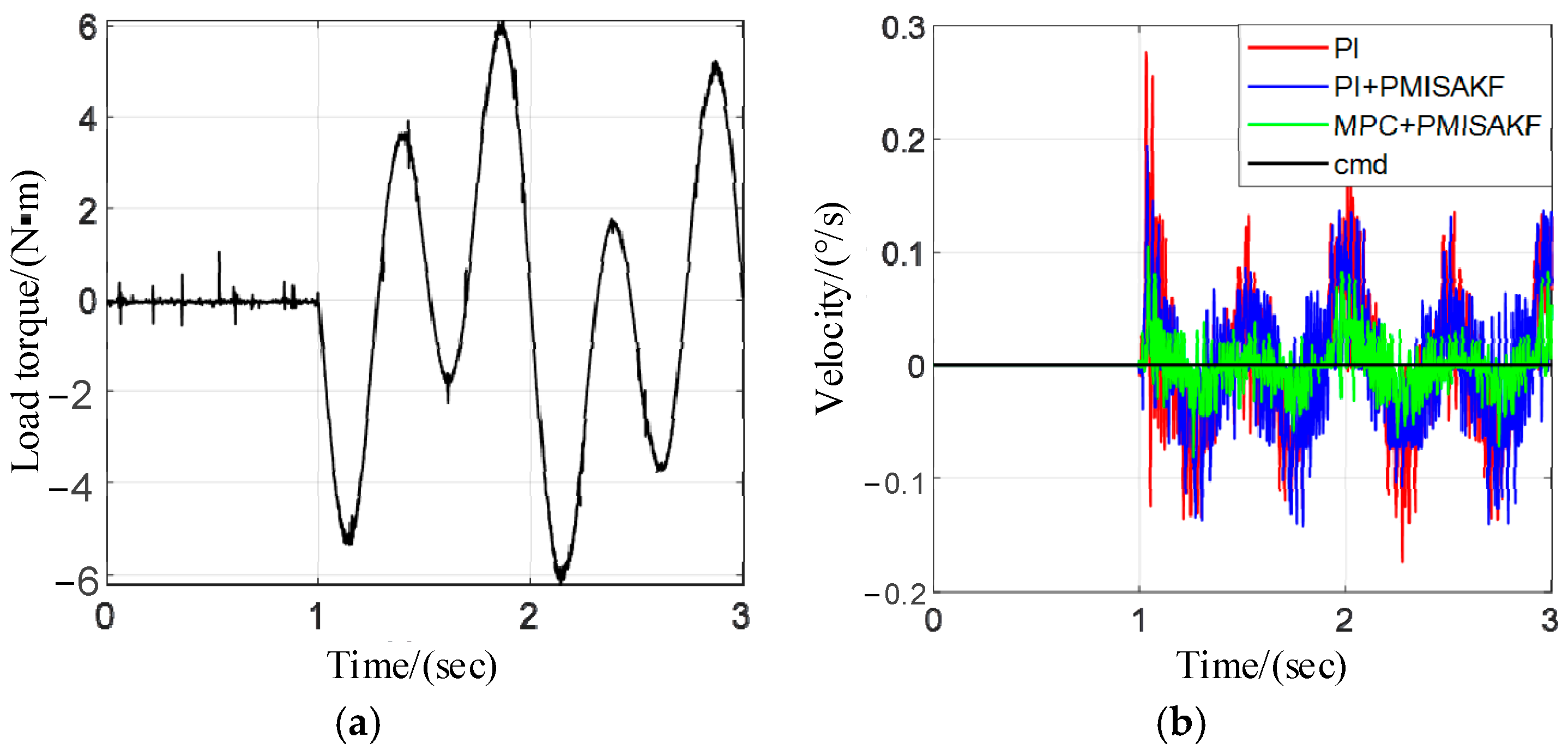
Using the load simulation device to simulate the carrier disturbance, we can test the control performance of the EMA under the external disturbance. According to the literature, the carrier disturbance can be approximated by the superposition of multiple sinusoidal signals. We represent it using three principal components, namely 1° and 1 Hz, 2° and 0.5 Hz, and 0.5° and 2 Hz. During the testing process, we set the speed command to zero, apply the carrier disturbance at the first second moment, and observe the speed fluctuations of the system under different control methods. The results are shown in
Figure 10. We take the peak-to-peak value of velocity fluctuations as statistical values and record them in
Table 4. The experimental results show that, in Method 2, the peak-to-peak value is reduced by 25% and, in the proposed method, this indicator is reduced by 60.42%. These experimental data further verify that the proposed method can effectively improve the system’s anti-interference ability.
