Abstract
Undoubtedly, wind turbines are currently one of the most significant contributors to clean energy. Therefore, it is crucial to enhance the capability of wind turbines, which in turn leads to an increase in their dimensions. Nevertheless, only advanced control systems can guarantee the optimal and secure operation of these huge machines. On the other hand, the precise control of these modern wind turbines is only achievable through the use of highly specialised actuators. Despite their importance, actuators have historically been overlooked and seen as secondary components in control systems. However, in modern machines, actuators are required to manipulate multiple tonnes or manage thousands of volts and amperes within short times. Consequently, greater emphasis must be placed on their handling and operation. This study aims to review actuators for modern large wind energy converters from a control engineering perspective, using a tutorial approach.
1. Introduction
The operation of wind turbines is impossible without control systems, which are linked to the machine by means of sensors and actuators. In the evolution of wind turbines, where the machines have rapidly increased in size, sensors and actuators have become a difficult technological hurdle. On the one hand, sensors must be able to measure powers of several MW, forces of several MN, and moments of several MNm. On the other hand, actuators must be able to handle masses of many tonnes in mechanical subsystems, as well as several kA and kV in electrical subsystems.
Some wind turbine subsystems are frequently ignored or oversimplified in the modelling process. Actuators are one example of such devices. It is often unnecessary to have models with additional complexity. Hence, it is useless to include more equations in the model. Today, control systems are expected to handle more challenging issues, such as huge and slow actuators, requiring the use of more complex dynamic models [1].
This applies, for example, to the pitch actuators, where the pitch control system exerts increasing pressure. Fault-tolerant control can, therefore, be implemented with a more complex pitch actuator model (see [2,3]). Something akin to this might be considered for a yaw actuator. Yaw systems consider solely electric actuation, whereas pitch systems are designed for both hydraulic and electric actuation.
The wind turbine can be decomposed using decomposition and coordination techniques [4] in several subsystems, such as the aerodynamic, rotor, drivetrain, generator, tower, and actuation subsystems. In principle, three actuation subsystems can be mentioned: pitch, yaw, and power electronic subsystems. All subsystems are coordinated by variables. An example of a spatio-temporal decomposition with highlighted actuation subsystems is shown in Figure 1.
Figure 1.
Wind turbine system decomposition with highlighted actuator subsystems.
This study is addressed to three-bladed, downstream, variable pitch, variable speed, and very large wind turbines, the purpose of which is to review the most important key elements of actuators related to wind energy converters from an automatic control perspective. The formulation is approached from a tutorial viewpoint, with a particular emphasis on modelling considerations. The paper is structured in the following manner: Section 2 is devoted to the pitch systems, followed by the yaw systems in Section 3. Next, in Section 4, power converters as actuators for torque control are described. Section 5 is dedicated to describing briefly the actuator control problem. Section 6 discusses mathematical tools for assessing actuator performance. Actuators for smart blades are shortly introduced in Section 7 for the sake of completeness. Section 8 is focused on drawing conclusions.
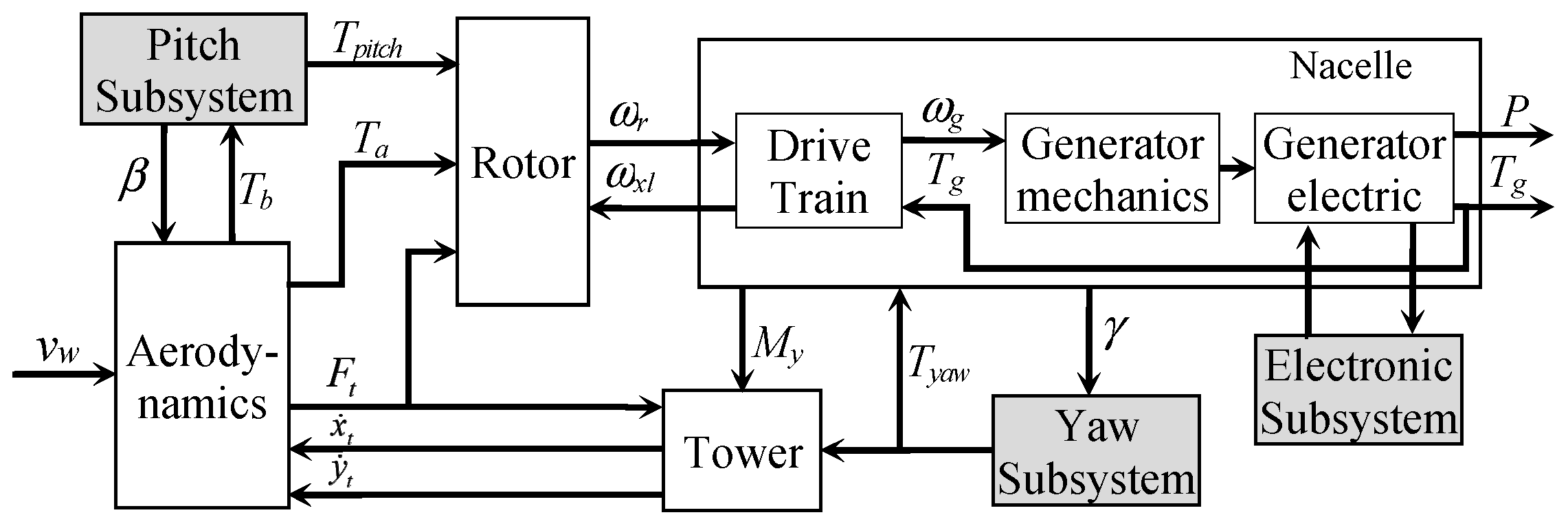
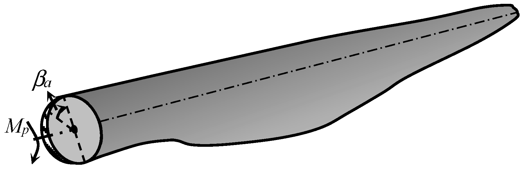
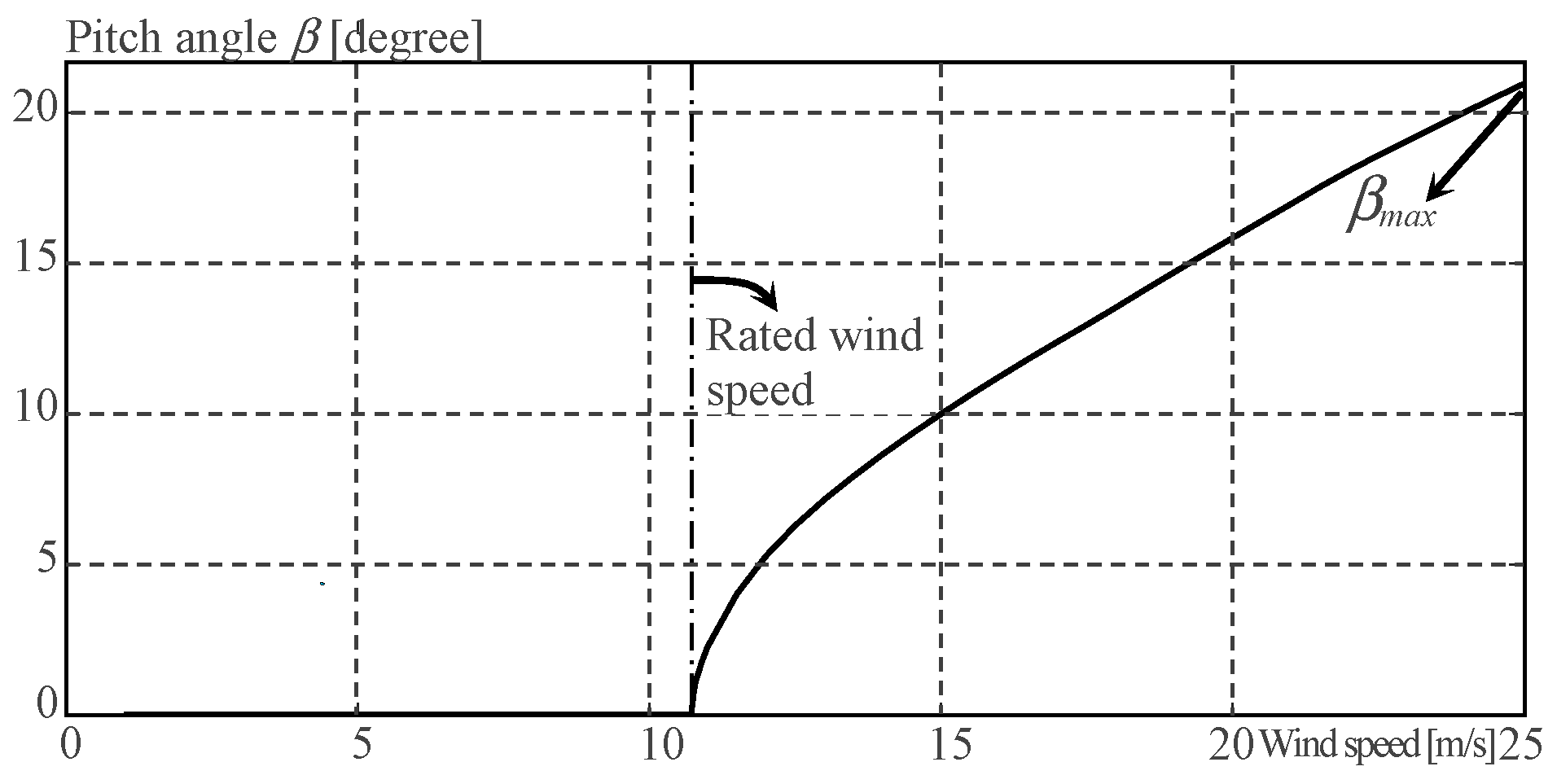
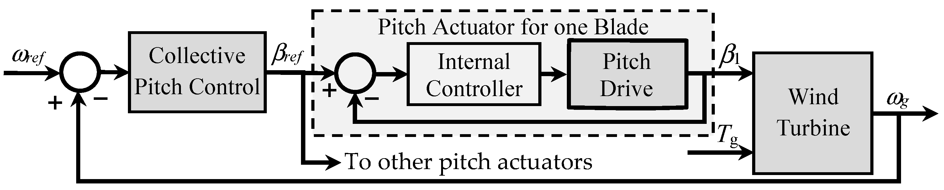
2. Pitch Actuating Systems
The pitch actuation entails the rotation of blades around their longitudinal axis to adjust the angle of the attack in accordance with the relative wind speed. Hence, pitch dynamics can be described as a rotational motion around the pitching axis, as depicted in Figure 2.
Figure 2.
Pitch motion of a blade along the longitudinal axis.
On the other hand, the pitch dynamics of wind turbines encompass the rotation of all the blades around the azimuth angle, in addition to the turning on the pitch axis. Furthermore, the blades are elastic, which results in a variable second moment of inertia with respect to the pitching axis, and they depend on the angle of deflection, the azimuth angle, and the pitch angle. Consequently, all dynamics are very complex, but a very simple model, including the actuator, is sufficient for the control system design. A model of the pitch dynamics is examined with details in [5].
The model used here considers a rigid, non-rotating blade whose motion equations are formulated by:
where β is the pitch angle, Jpe is the equivalent second moment of inertia with respect to the pitch axis, Bpe is the equivalent torsional damping coefficient, and Kpe is the equivalent torsional stiffness coefficient. The torque applied to the blade by the actuator is np Tpa, with the np as a gear ratio that considers the toothing of the pinion and blade bearing as well as the pitch actuator gearbox. Tb is a torsional moment resulting from dynamic and aerodynamic forces that act as disturbances on the blades. At last, the frictional moment generated by the bearing is denoted as Tf.
It should be noted that the torsional moment Tb is normally unmeasurable, but it can be estimated using a simulation program. By using the formula
from [6], the bearing frictional moment can be empirically obtained for ball and roller bearings.
The formula has its origins in experimental data obtained from a product series, and as a result, its validity range is highly limited. Nevertheless, the formula can be curve-fitted with the availability of data coming from other bearings. The radial and axial forces working on the bearing are symbolised by FR and FA, respectively. The bearing friction μ depends on the bearing type and is often provided by the manufacturer. Fitted coefficients α1 and α2 are also specific for a given bearing. Mb denotes the resulting blade root bending moments, while Db is the bearing diameter.
2.1. Simple Models of Pitch Actuator
2.1.1. Pitch Actuator as First Order System
The electromechanical nature of the wind energy converter typifies that the system has very different time constants. Mechanical components have large inertia with slow reaction times, while electrical devices are very fast. On the other hand, pitch drivers are situated in between, i.e., they are faster than the mechanical subsystem but slower than the electrical one. These considerations about the time constants justify the idea of using a very simple model for the pitch actuators. Hence, first-order models are often used to this end, as reported in, e.g., [7,8,9]. A typical first-order model for a pitch actuator is formulated in [10] as follows:
whose block diagram is depicted in Figure 3.
Figure 3.
A typical first-order pitch actuator in the form of a block diagram.
Variables βref, βmax, and βmin are pitch angle reference, upper bound, and lower bound, respectively. τb is the time constant. Pitch actuators are normally constrained in travel and rate. The travel goes from −3 or −4 to 25–30 degrees in normal overspeed operation and up to 90 degrees in shutdown operation. The rate is limited to ±8 or ±10 degree/s in order to avoid large loads on the blades. Sometimes, it is necessary to filter out low pitch rates smaller than ±0.1 degree/s to avoid noise and excessive pitch activity around zero. This is implemented in [11] using a rate limiter with a dead zone.
First-order models have drawbacks, such as the absence of an initial delay and the inability to model oscillating behaviour. These issues are improved by a second-order model.
2.1.2. Pitch Actuator as Second Order System
Following the idea of simple models for the pitch actuators, a second-order model, as suggested in [12], can be used. More advanced second-order models can include constraints and dead time, as proposed in [13,14]. Thus, the corresponding equation is as follows:
and the graphical representation is depicted in Figure 4.
Figure 4.
Typical representation of a second-order pitch actuator.
Parameters ζ and ωn are the damping ratio and the eigenfrequency, respectively. Tt is the dead time. Depending on the wind turbine dynamics, the damping ratio can vary between 0.6 and 0.9 and the eigenfrequency between 8.88 and 11.11 rad/s (see, for instance, [15,16,17]). Notice that βmax is the maximum amplitude constraint, which is selected to keep constant the rotor speed for the maximum wind speed. A typical dependence between wind speed and pitch angle is depicted in Figure 5. βmax must be changed to 90 degrees in the shutdown operational state.
Figure 5.
The pitch angle depends on the wind speed for normal overspeed operation.
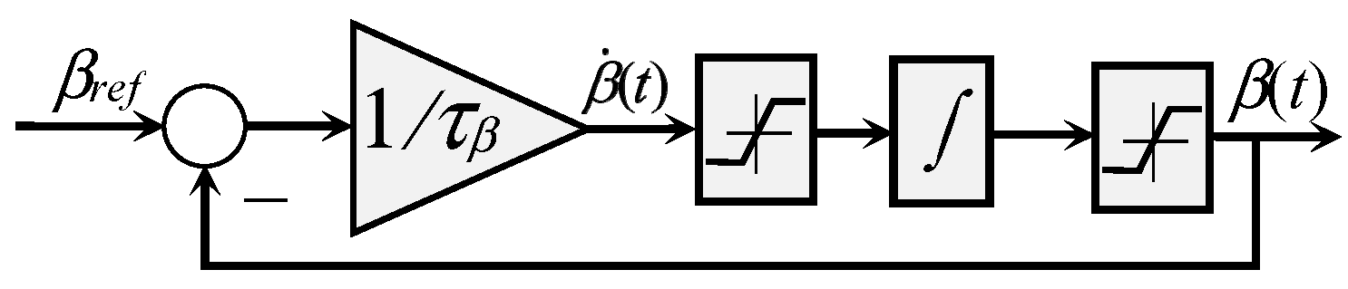
2.1.3. Pitch Actuator with Pitch Rate Reference
Modern pitch actuators normally contain an internal servo controller whose reference variable is a rate signal instead of an angle signal. For this reason, it is convenient to express the model of the pitch actuator in terms of rates. Hence, the model can be modified in order to accommodate pitch rates. One way to accomplish this is to modify the model of Figure 3, as shown in Figure 6.
Figure 6.
First-order pitch actuator with pitch rate set point.
2.2. Modelling Pitch Actuators Using Physical Principles
All the above-described models are generic and normally sufficient for control purposes. However, they cannot study and simulate the internal interactions of different actuator components. Hence, the physical representation of the actuators becomes useful.
Pitch actuators for wind turbines typically are based on two different technologies: electromechanical and hydraulic drives. Hydraulic systems are, on the one hand, more robust, stiffer, with less backlash, and offer more torque; on the other hand, they are larger and slower to respond. For this reason, hydraulic solutions are considered in machines subjected to high aerodynamic loads. Contrarily, electromechanical systems are prone to failures and have a lower strength, but their fast reaction time makes them more appropriate for fast control, such as individual pitch control (IPC). Both drivers are analysed in the following.
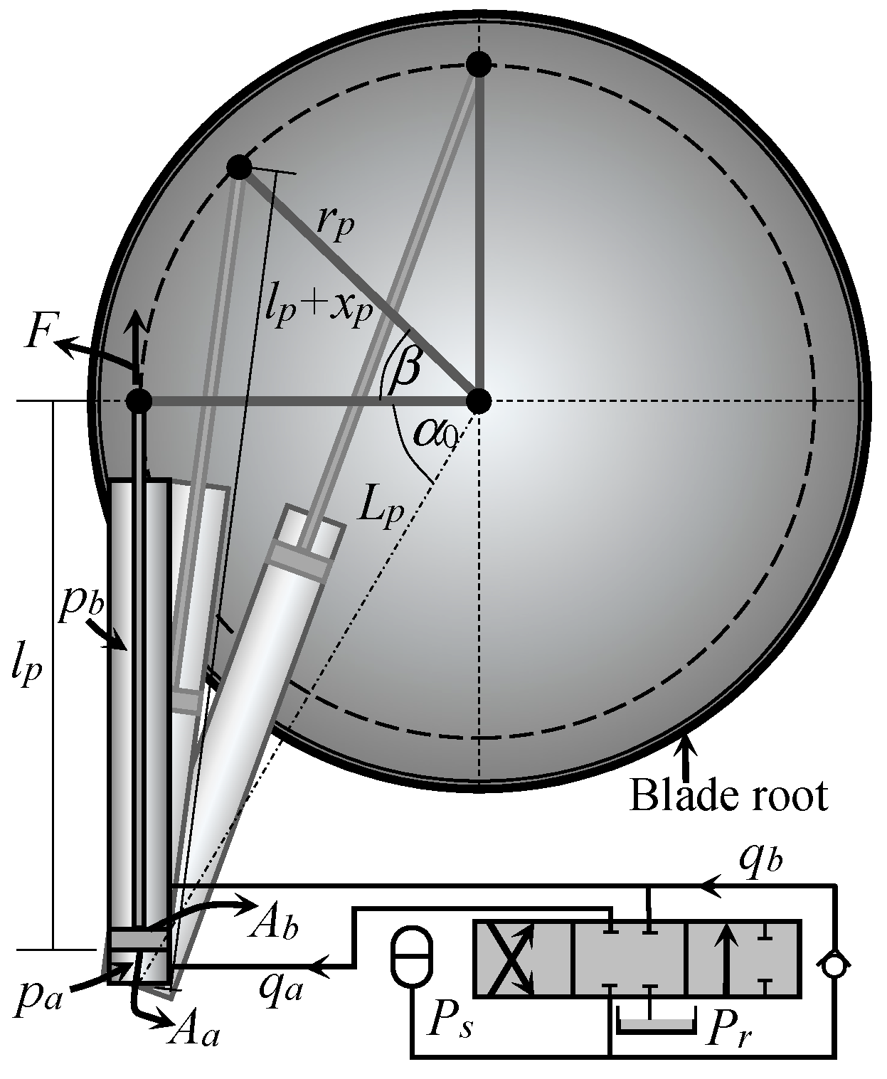
2.2.1. Hydraulically Driven Hydraulic Pitch Actuators
A hydraulically driven pitch actuator follows the same concept as many other hydraulic devices. It comprises a set-up of a hydraulic pump, a tank, an electrohydraulic-commanded proportional valve, a relief valve, and a hydraulic cylinder. A simple scheme of a hydraulic pitch drive is shown in Figure 7.
Figure 7.
Simplified hydraulic pitch actuator [1].
Several dynamic models are available for hydraulic pitch actuators, for instance, in [2,18,19]. The main duty of the actuator is to rotate the blade. To this end, it must provide a torque Tpa greater than the bearing friction moment and the aerodynamic pitching torque. Hence, the torque can be expressed by
where fp(β) is a functional relationship between piston force and the pitching moment defined as follows:
Fp is the piston force, rp is the actuator torque arm, xp is the piston rod position, and β is the pitch angle. With the help of Figure 7, the relationship between xp and β can be derived and expressed as follows:
where α0 is the angle between the pitch axis and the axis of the pitch to centre for xp = 0, and Lp is the length from pitch to centre. Thus, α0 can be calculated from
Deriving (7) into β follows
The pitch angle β is also obtained from (7) as
The resulting force Fp is then given by the sum
The pressures applied on the respective piston areas Aa and Ab are denoted as pa and pb. The final term refers to the viscous damping force applied to the moving piston. Equation (9) provides the basis for computing the derivative of xp as follows:
which leads to
In order to solve (11), pressures pa and pb in the cylinder are necessary. They satisfy the first-order laws given by (see [20])
Parameters Ba and Bb denote the effective bulk moduli in chambers a and b and the associated volume flow rates by qa and qb. The control signal is denoted by u, and chamber volumes Va and Vb depend on xp, namely
with Va0 and Vb0 being unusable piston volumes. The piston stroke is ls. Hence,
expresses the flow rates throughout the chambers, where pr and ps are the ambient pressure and the pressures provided by the pump [20]. kv denotes the valve coefficient. The proportional control law
provides the control signal u(t). The piston dynamics is finally modelled by the second-order motion
where the stiffness, the damping coefficient, and the piston mass are denoted by kp, bp, and mp, respectively.
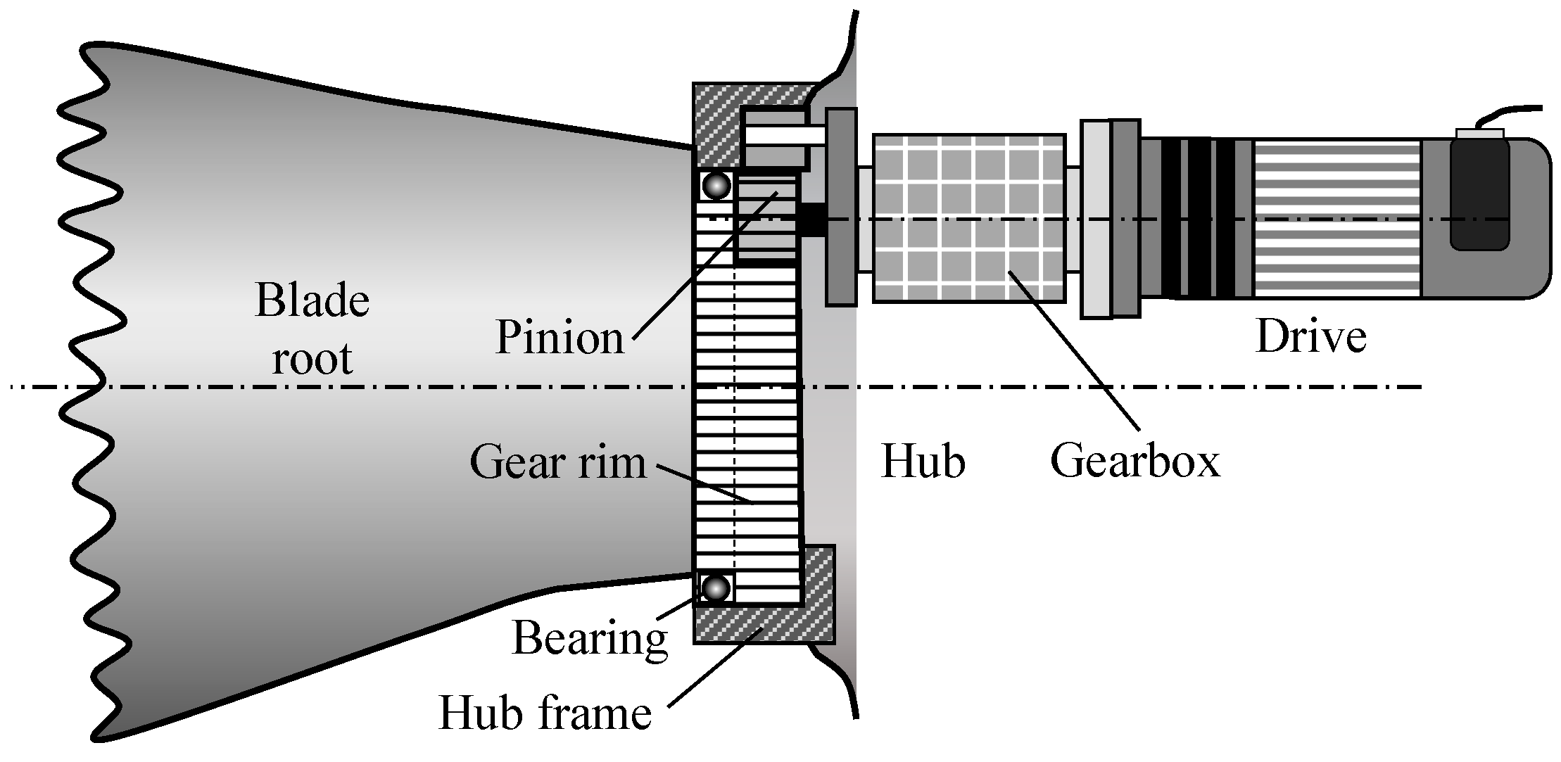
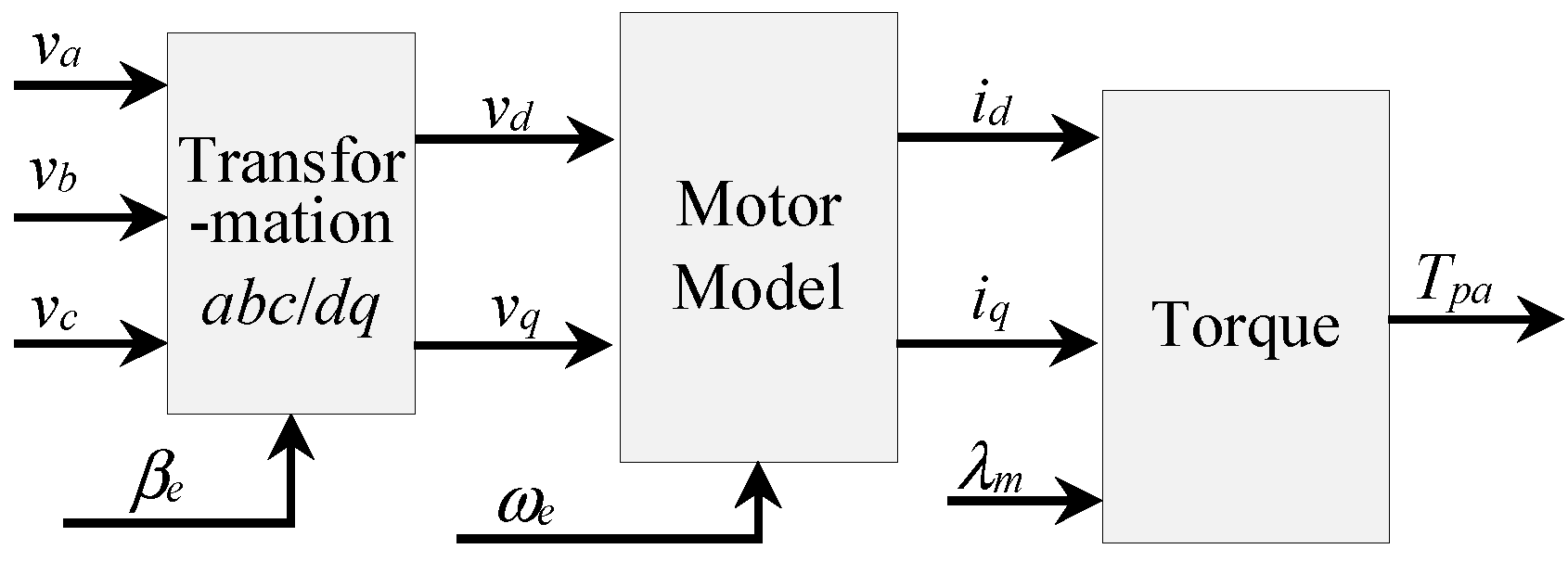
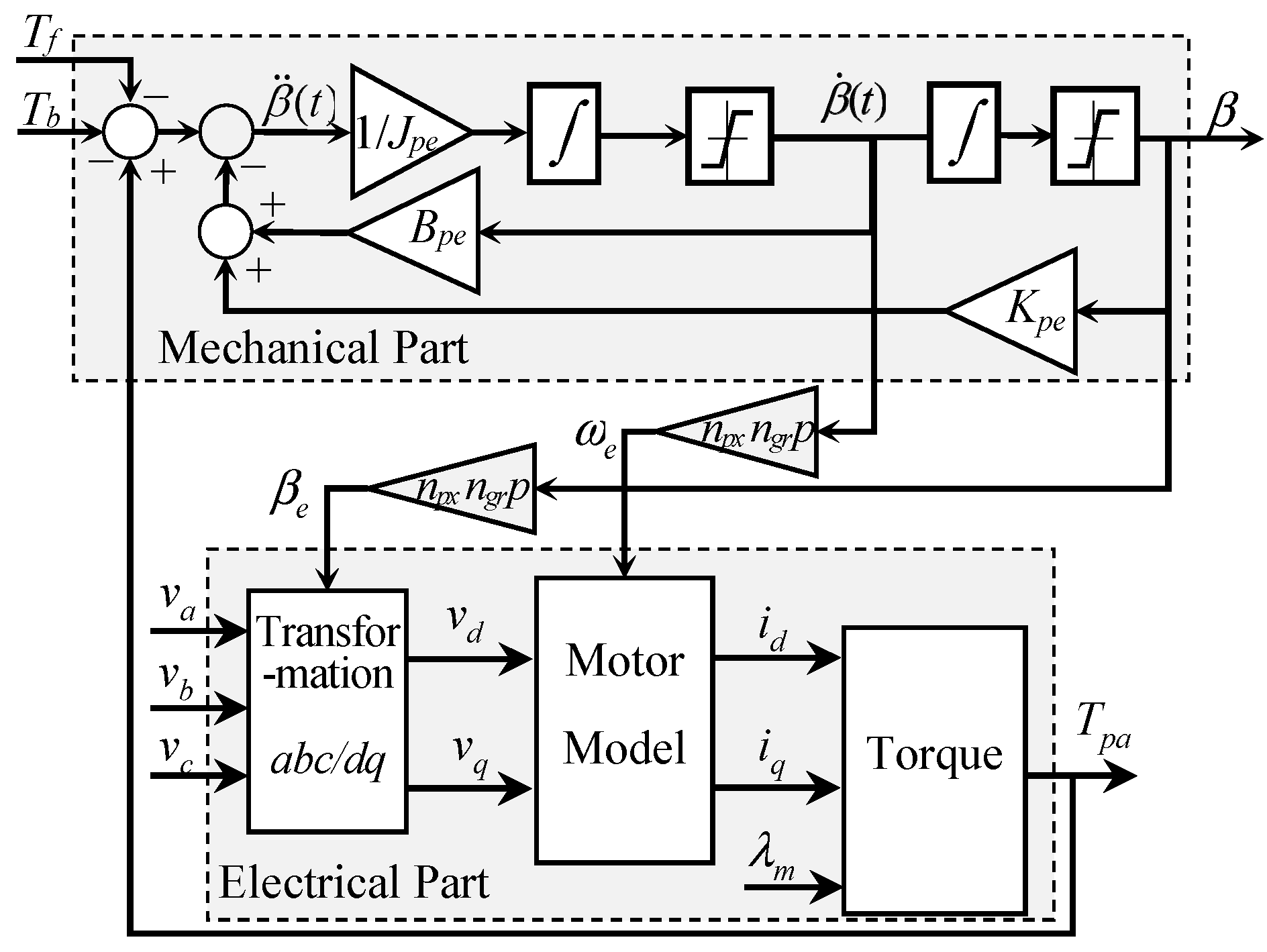
2.2.2. Electrically Driven Pitch Actuators
In essence, an electrically driven pitch actuator comprises a gearbox coupled with an electrical motor. It is coupled with the blade root through a pinion that engages with a bearing and a gear rim. A scheme of such an actuator is depicted in Figure 8.
Figure 8.
Schematic electrical pitch actuator [1].
Any type of electric drive can be used to assemble a pitch actuator. However, the most commonly used today are permanent magnet synchronous motors. Mechanical components follow the motion Equation (1) but are expressed in terms of the blade and motor parameters, namely
with
where the stiffness coefficients, damping coefficients, and mass moments of inertia for the blade and motor are represented by Kpb, Kpm, Bpb, Bpm, Jpb, and Jpm.
The electric part is expressed by using the motor convention in the rotating dq reference frame [21]. The mathematical modelling includes the first-order differential equations
and the dq-transformation
The three-phase input voltages are denoted by [va vb vc]T. The electrical speed is ωe, and the electrical rotational angle is βe. The electrical parameters are Lq and Ld as the self-inductances, λm as the flux linkage between the stator and the rotor, and Rs as the stator resistance. Finally, the electrical torque with p as the number of pole pairs is given by
Figure 9 shows a scheme of the electrical components.
Figure 9.
Block diagram of a synchronous motor within the dq-reference frame.
The mechanical pitch angle is related to the electrical rotational angle according to the relationship
where ratios of gear rim and gearbox are denoted by ngr and npx, respectively. Thus, the electrical speed links to the pitch rate by
Figure 10 illustrates a schematic diagram of the whole pitch actuator.
Figure 10.
Electric pitch actuator.
In the end, a second-order model is used to represent the electrical subsystem, whereas another second-order model is applied to model the mechanical components. Thus, the entire model becomes fourth-order.
Based on the premise that the electrical subsystem exhibits significantly faster dynamics than the mechanical components, the electric subsystem can be viewed as being in a steady state, and hence, the pitch actuator behaves according to second-order dynamics.
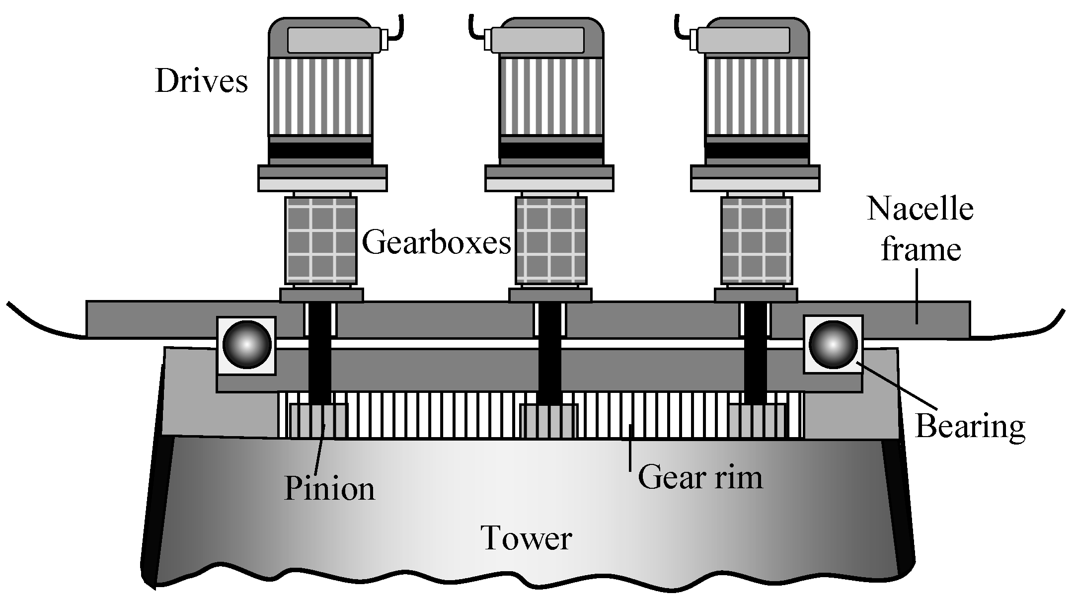
3. Yaw Actuating Systems
The principal objective of the yaw subsystem is the maximisation of the captured energy via maintaining the machine orientated in the direction of the wind by means of accurate direction tracking. Although hydraulic yaw actuators are possible, they are essentially electric. Hence, yaw systems comprise multiple electric motor drives synchronised by a common control signal. In essence, yaw drives use the same concept as electric pitch drives, including an electric motor, gear rim, pinion, and planetary gearbox. Furthermore, the yaw rim and yaw brakes are attached together in order to secure the rotor remains in its 90-degree orientation with respect to the wind direction or during maintenance procedures. The yaw mechanism commonly provides a considerable yaw torque to move the nacelle. A schematic representation of a six-driver yaw system is shown in Figure 11, where three drives are maintained behind the visible ones to improve the legibility of the diagram.
Figure 11.
Scheme of a yaw system with several-drives [1].
It is assumed, for the sake of simplicity, that the drive assembly comprises my identical synchronous motors with the same electrical models as provided by (24)–(26). The applied torque that is required for the nacelle rotation is determined by
The wind rotor aerodynamics, including factors like wind shear, skewed wake effects, horizontal and vertical wind components, and blade rigidity, have an important contribution to the yaw motion, resulting in quite complex yaw dynamics, which is, in turn, very difficult model. Therefore, a simplified model for control purposes is given by
is considered here. Jye is the equivalent second moment of inertia around the yaw axis, including the rotor and nacelle; Kye denotes the torsional stiffness coefficient; and Bye represents the torsional damping coefficient. The yaw angle is denoted by γ. The torque applied by the yaw actuators multiplied by ny is denoted by Tya, where ny is the gear ratio that considers the gearbox ratio of the yaw actuator and the toothing of the yaw bearing and pinion. In addition, the equation contains two more moments: Ty, which is a torsional moment for all external moments acting in the yaw-axis direction, and Tyf is the yaw-bearing frictional moment.
The primary contributing factor to Ty is the resulting blade root bending moment translated to the yaw axis. It is estimated in [22] by using
with
where Ft,max is the maximum thrust force in the wind direction, R is the rotor radius, rcg is the location of the gravity centre, mb is the blade mass, and g is the gravitational acceleration. For the frictional moment Tyf, the estimative formula is provided in [6], i.e.,
The tilting moment working on the bearing is denoted in (34) by Mt.
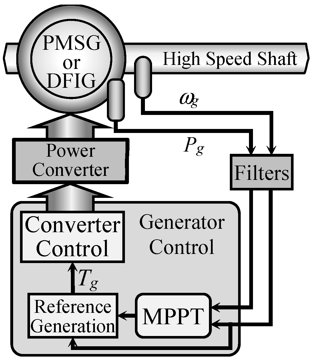
4. Power Converters as Actuators
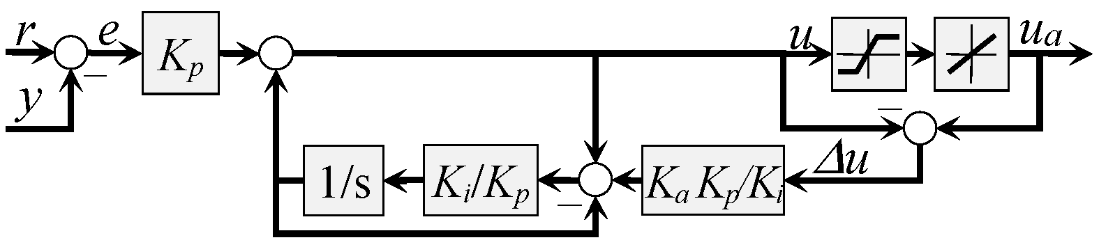
When the wind speed is sufficiently fast to convert energy but not high enough to reach the nominal operation, the primary control goal is to maximise power extraction. Nevertheless, this goal can only be achieved with variable-speed wind turbines, as their operation relies on the separation between the generator and the power network facilitated by power converters.
To this end, the sole relevant input variable is the electromagnetic generator torque. By manipulating this variable with a power converter, it is possible to follow the generator characteristic curve, obtaining the maximum possible power capture. The control system configuration comprises three stages. The initial stage involves implementing the control law, which generates the control signal for the subsequent phases. In the second stage, a reference signal is generated to govern the power converter. Lastly, the third stage involves the low-level control device responsible for managing the power electronics. The approach is illustrated in Figure 12.
Figure 12.
Scheme of the torque control.
Hence, the power converter serves as an interface between the control system (MPPT, maximum power point tracking) and the generator, fulfilling the role of an actuator. There are several types of power converters, depending on the generator type. Modern wind turbines have attached either a permanent magnet synchronous generator (PMSG) or a double-fed induction generator (DFIG). In both cases, bidirectional back-to-back power converters are used, although connected differently. A schematic back-to-back power converter is shown in Figure 13.
Figure 13.
Scheme of a back-to-back power converter.
Back-to-back power converters are built using two voltage source converters (VSC) connected by a DC link, where the VSCs are normally controlled using the pulse-wide modulation (PWM) technique with variable modulation index. Power converters, their operation, and control are part of a wide discipline within electronics, whose details exceed the scope of the present contribution. To delve further, interested readers may refer to [23,24,25,26,27].
The active power, PG, and reactive power, QG, transferred from the generator to the power converter are calculated by (see, e.g., [28])
where vG and vC are the magnitude of the generated voltage and the magnitude of the converter output voltage, respectively. The electric phase angle between the voltages is represented by δ, whereas the equivalent generator reactance is denoted by XG.
To regulate the magnitude of the vC output voltage, one can adjust the amplitude modulation index. Similarly, the phase angle can be controlled by adjusting the phase angle of a reference voltage Vref in relation to the generated voltage.
5. Actuator Control
Pitch and yaw actuators are mechanisms designed to precisely move blades or the nacelle to a specified position, necessitating a certain level of accuracy. In order to accomplish this, actuators rely on an internal low-level controller that is interconnected in a cascade configuration inside the entire control system. The internal controller is typically pre-configured and unreachable from the outside. An example of this topology for one blade of the pitch system is depicted in Figure 14. A similar scheme is also found in yaw actuator systems. Low-level controllers for power converters are often implemented as PWM devices and can be studied in [24] or [27].
Figure 14.
The pitch control system in a cascade configuration.
Controllers with integral actions, such as PI or PID controllers, are susceptible to the integrator windup problem, which refers to the blow-up of the integrator as a result of saturated actuator outputs. The problem has been intensely studied in the past for actuators with saturated magnitude (see, e.g., [29,30,31]). Nowadays, the most popular anti-windup procedure is known as back calculation, which was proposed in [32].
However, pitch and yaw actuators experience saturation in both amplitude and rate, which limits the loads generated by the actuation on the wind turbine. This hurdle is addressed in [33], which proposes an anti-windup mechanism based on the automatic reset configuration [34]. The concept is described in Figure 15.
Figure 15.
Anti-windup in automatic reset configuration for magnitude and rate limitations.
6. Assessment of Performance for Actuator Protection
Actuators supply power and correct the control signals as the interface between the wind turbine and controller. On the other hand, they also add to the control system’s retards, restrictions, and nonlinearities. An indirect evaluation of control signals can be achieved by utilising performance indices [35], which quantify the energy with the control signals. Furthermore, they restrict the magnitudes of the control signals and derivatives to the actuator limits. As previously described, anti-windup methods can overcome or at least mitigate nonlinearities.
All previously discussed factors pertaining to actuators fail to account, especially in the context of wind energy converters, that their operation is uninterrupted because of the unpredictable variations in wind speed and direction. Consequently, the actuators experience continuous and escalating deterioration until they fail or even collide. Therefore, a key goal of the control system should be to balance all factors, including those related to the time for which the actuator operates, without any failures. The present section is devoted to introducing these aspects.
6.1. The Concept of Actuator Travel
Actuator travel refers to the overall distance covered by an actuator during a single cycle, starting with its activation and finishing with its deactivation. In [36], the metric is expressed by
with ua denoting either the yaw or the pitch angle, while JAT represents the overall angle traversed.
6.2. The Concept of Actuator Duty Cycle
The duty ratio, which is likewise referred to as the duty cycle, represents the difference, expressed in percentage, between a complete cycle and the working periods. The total cycle considers on-time and off-time periods (see, e.g., [37,38]). It can be mathematically formulated by
Hence, a continually operating actuator has a duty cycle of 100%.
However, there are other definitions. For instance, in [39], the duty cycle is the duration of actuator activity before needing cooling, while in [40], it is the average of actuator travel (36) and is given by
This definition is also applied in [35]. Equation (38) is the classic time-limited integrated absolute derivative index (IADE) but applied to the control variable ua(t) rather than the control error.
Though the actuator fatigue is not quantified by this metric, it provides a valuable objective function for assessing control strategies in terms of how they affect the actuators. The function can be utilised for evaluation during the procedure by setting tmax as the present time t. In [41], (38) is normalised and afterward employed in [42,43], i.e.,
Furthermore, the metric has been adjusted to account for actuators having an asymmetric span in [44], resulting in the formula
To date, the metrics have been established for a single simulation. However, it is possible to conduct successive simulation runs for various average wind speeds , resulting in a collection of actuator duty cycles as a consequence of a collection of simulations. These cycles are then indexed as JnADC(i), where i varies from 1 to the number of simulations ns.
Moreover, the wind speed of each simulation can be weighted by a Weibull-distributed probability pw covering the entire lifespan of the machine [41,42,43], such that a weighted actuator duty cycle can be built according to
Hence, the lifespan of the actuator duty cycle is evaluated using (41). Nevertheless, the computation takes place offline and serves the purpose of comparing the performance of various controllers. However, it is unsuitable for online assessment of control performance or offline control system design.
Finally, the design load cases (DLC 1.2, [45]) can be used to generate a set of simulations according to the description provided in [41,42,43].
7. Actuators for Smart Blades
Very large rotor blades are flexible and affected by the spanwise variability of the wind. Therefore, the capacity of standard load control strategies to mitigate loads is reaching its limits. In the search for novel solutions, active flow control seems to be a way to overcome the problem. The idea is to provide the blades with additional devices in order to treat the load locally. They are called smart or intelligent blades.
Currently, smart blades remain in the research phase, and actuators associated with this technology are not yet commercially accessible for wind energy converters. Therefore, they are briefly discussed here only for the sake of completeness.
Thus, smart blades might be categorised into two distinct types: active and passive smart blades. Passive blades mitigate variations in wind speed by adjusting the aero-elastic behaviour of the blades, which is facilitated by the physical properties of the materials involved, such as bend-twist coupling, tension-torsion coupling, and sweep-twist coupling (see, for instance, [41,46,47], for further details). As a passive blade system, they do not need special or additional actuators; therefore, they are not interesting for the present work.
On the other hand, active, intelligent blades are designed to mitigate loads by manipulating the aerodynamic characteristics of the blades. This can be achieved by incorporating elements that enable partial adjustment of the angle of attack or lift coefficient. Thus, the flow passing around the aerofoils can be controlled. The mentioned elements are, for instance, trailing edge flaps, morphing trailing edge flaps, Gurney flaps, and microtabs, among others (see Figure 16 for examples).
Figure 16.
Smart aerofoils: (a) trailing edge flaps; (b) morphing trailing edge flaps; (c) Gurney flaps.
Individual flap control (IFC) is the approach that makes use of trailing edge flaps to reduce blade loads. In particular, IFC is combined with IPC (individual pitch control) to obtain the best result (see, e.g., [48,49,50] for hybrid approaches). Details about the needed actuators and their specifications for flap control are given in [51].
The traditional actuation for the flaps is electrical servo motors, but in the last few years, plasma actuators, in particular for morphing trailing edges, have gained attention in order to get controlled deformations of the flaps. Thus, plasma actuators are combined with Gurney flaps in [52] and for morphing trailing edges in [53]. See [54] for a review of plasma actuators in wind energy systems.
The mechanical structure of plasma actuators is one of their main advantages; their compact size and sturdy design make it simple to integrate them into the blades. In addition, their size and maintenance contribute to their low cost. On the other hand, they are vulnerable to a variety of factors, including frequency, supply voltage, and wetness [55,56].
8. Conclusions
Although actuators are essential, they are often characterised primarily from a technical perspective, with little attention given to their control and mathematical modelling aspects. Therefore, there is a scarcity of research that examines wind turbine actuators from a comprehensive viewpoint. Hence, it is the objective of this study.
From a functional perspective, wind turbine actuators can be categorised into three broad groups: blade pitch motion actuators, yaw motion actuators, and generator electrical control actuators. The first two devices are either electromechanical or hydraulic in nature, whereas the third device is exclusively electronic.
The necessary attributes were analysed, mathematical models with different levels of complexity were presented, and an effort was undertaken to offer a presentation with a didactic component.
In addition, the survey examined specific challenges in the control loop, such as anti-windup problems. Furthermore, this study accounted for the assessment of actuator performance for both the analysis and the design of the control system.
Finally, a brief exploration of what are known as intelligent blades was undertaken to address the actuation concerns.
Funding
This research received no external funding.
Institutional Review Board Statement
Not applicable.
Informed Consent Statement
Not applicable.
Data Availability Statement
Data are available upon request from the corresponding author if allowed by the affiliating institution.
Conflicts of Interest
The author declares no conflicts of interest.
Abbreviations
| CPC | Collective Pitch Control |
| DFIG | Double-Fed Induction Generator |
| DLC | Design Load Cases |
| HPPT | Maximum Power Point Tracking |
| IADE | Integrated Absolute Derivative |
| IFC | Individual Flap Control |
| IPC | Individual Pitch Control |
| PI, PID | Proportional Integral, Proportional Integral Derivative |
| PMSG | Permanent Magnet Synchro Generator |
| PWM | Pulse-Wide Modulation |
| VSC | Voltage Source Converters |
| Nomenclature | |
| Parameters | |
| Aa, Ab | Areas of chambers a and b of a hydraulic piston, m2 |
| Ba, Bb | Effective bulk moduli of chambers a and b of a hydraulic piston |
| bp | The damping coefficient of the piston, Nm s/rad |
| Bpe | Equivalent torsional damping coefficient, Nm s/rad |
| Bpb, Bpm | Torsional damping coefficients of blade and motor, Nm s/rad |
| Bye | Torsional damping coefficients on the yaw axis, Nm s/rad |
| cp | Proportional constant for the piston force |
| Db | Bearing diameter, m |
| g | Gravitational acceleration, m/s2 |
| Jpe | Equivalent second moment of inertia, kg m2 |
| Jpb, Jpm | The second moment of inertia of the blade and motor, kg m2 |
| Jye | The second moment of inertia on the yaw axis, kg m2 |
| Kp | The stiffness coefficient of the piston |
| kv | Valve coefficient |
| Kpe | Equivalent torsional stiffness coefficient |
| Kpb, Kpm | Torsional stiffness coefficients of blade and motor, Nm s/rad |
| Kye | Torsional stiffness coefficients on the yaw axis, Nm s/rad |
| lp | Piston length, m |
| Lp | Pitch-to-centre length, m |
| Ld Lq | Self-inductances, H |
| mp | Piston mass |
| mb | Blade mass, kg |
| my | Number of yaw actuators |
| ny | Yaw actuators multiplied |
| np | Gear ratio including toothing of pinion and blade bearing, -- |
| npx, ngr | Gearbox and gear rim ratios, -- |
| p | Number of pole pairs, -- |
| ps, pr | Pump pressure, ambient pressure, P |
| rp | Actuator torque arm, m |
| rcg | Location of the gravity centre, m |
| R | Rotor radius, m |
| Tt | Dead time, s |
| Va, Vb | Volumes in chambers a and b of a hydraulic piston, m3 |
| Va0, Vb0 | Unusable volumes of chambers a and b of a hydraulic piston, m2 |
| XG | Equivalent generator reactance |
| α0 | The angle between the pitching arm and the pitch-to-centre axis, rad |
| α1, α2 | Fitted coefficients α1 and α2 for a given bearing |
| βmin, βmax, βref | Minimum, maximum, and setpoint values for the pitch angle, rad |
| μ | Bearing friction, N |
| τβ | The time constant, s |
| λm | Flux linkage between the rotor and the stator |
| ζ | Damping ratio |
| ωn | Eigenfrequency, natural frequency |
| Variables | |
| DC | Duty cycle |
| FA, FR | Axial and radial forces on the bearing, N |
| Ft | Thrust force in the wind direction, N |
| Ft,max | Maximum thrust force in the wind direction, N |
| Fp | Piston force |
| id, iq | d and q currents dq reference frame, A |
| JAT | Metric to evaluate the actuator travel |
| JADC | Metric to evaluate the actuator duty cycle after [41] |
| JnADC | Metric to evaluate the cycle after [42,45] |
| Metric to evaluate the cycle after | |
| Mb | Resulting in blade root bending moments, Nm |
| Mx, My | Components of root bending moments, Nm |
| Mt | Tilting moment working on the bearing, Nm |
| pa, pb | Pressures in chambers a and b of a hydraulic piston, P |
| pw | Weibull distribution |
| qa, qb | Flow rates in chambers a and b of a hydraulic piston, m3/s |
| PG | The active power output of a generator, W |
| QG | The reactive power output of a generator, W |
| Tpa | Torque applied to the blade by the actuator, Nm |
| Tb | Whole torsional moment, Nm |
| Tbm | Resulting in blade root bending moment, Nm |
| Tf | Frictional moment, Nm |
| Tpa | Electrical torque of a pitch motor |
| Ty | The torsional moment for all external moments acting in the yaw-axis direction |
| Tyf | Yaw bearing frictional moment |
| Tya | Electrical torque of a yaw motor |
| vG, vC | Voltages in the back-to-back converter |
| vw | Wind speed, m/s |
| Average wind speed, m/s | |
| Vref | The voltage reference for the power conversion |
| u | Control variable |
| xp | Piston rod position, m |
| va, vb, vc | Three-phase input voltages, V |
| vd, vq | d and q voltages, dq reference frame, V |
| β | Pitch angle, rad |
| βe | Electric rotational angle, rad |
| δ | Electric phase angle |
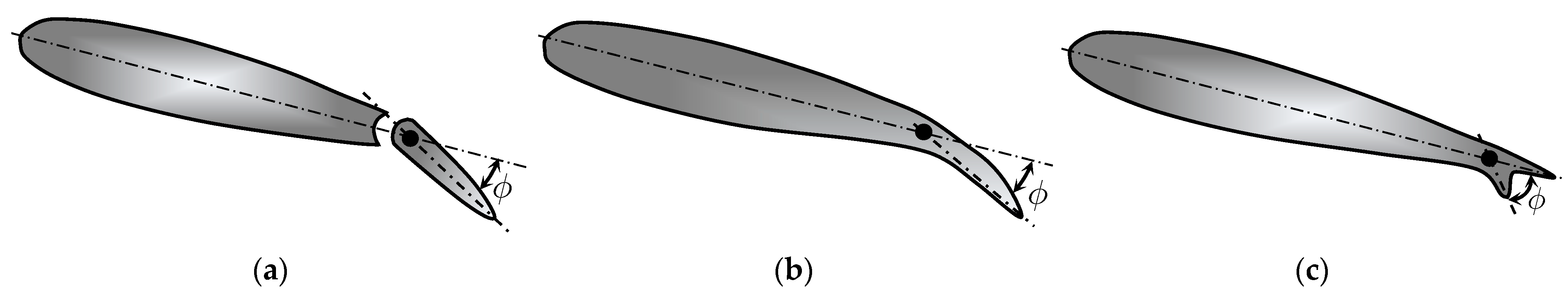
| ϕ | Deflection angle in trailing edge flaps, rad |
| γ | Yaw angle, rad |
| Functions | |
| fp(.) | Relationship between piston force and the pitching moment |
References
- Gambier, A. Control of Large Wind Energy Systems; Springer Nature: Basel, Switzerland, 2022. [Google Scholar]
- Rakoto, L.; Schorsch, J.; Kinnaert, M. Modelling hydraulic pitch actuator for wind turbine simulation under healthy and faulty conditions. IFAC-PapersOnLine 2015, 48, 577–582. [Google Scholar] [CrossRef]
- Tutiven, C.; Vidal, Y.; Acho, L.; Rodellar, J. A fault detection method for pitch actuators faults in wind turbines. In Proceedings of the International Conference on Renewable Energies and Power Quality, La Coruña, Spain, 25–27 March 2015; pp. 698–703. [Google Scholar] [CrossRef]
- Chen, H.; Zhang, Y. Power System Optimization: Large-Scale Complex Systems Approaches; John Wiley & Sons: Singapore, 2016. [Google Scholar]
- Kallesøe, B.S. Equations of motion for a rotor blade, including gravity, pitch action and rotor speed variations. Wind Energy 2007, 10, 209–230. [Google Scholar] [CrossRef]
- Erde, R. Slewing Bearings; Catalogue, Rothe Erde, GmbH: Dortmund, Germany, 2009. [Google Scholar]
- Bianchi, F.D.; de Battista, H.; Mantz, R.J. Wind Turbine Control Systems; Springer: London, UK, 2007. [Google Scholar]
- Geng, H.; Yang, G. Output power control for variable-speed variable-pitch wind generation systems. IEEE Trans. Energy Convers. 2010, 25, 494–503. [Google Scholar] [CrossRef]
- Fortmann, J. Modeling of Wind Turbines with Doubly Fed Generator System; Springer Vieweg: Wiesbaden, Germany, 2014. [Google Scholar]
- Georg, S. Fault Diagnosis and Fault-Tolerant Control of Wind Turbines. Ph.D. Thesis, University of Rostock, Rostock, Germany, 2015. [Google Scholar]
- Geng, H.; Yang, G. Linear and nonlinear schemes applied to pitch control of wind turbines. Sci. World J. 2014, 2014, 406382. [Google Scholar] [CrossRef] [PubMed]
- Odgaard, P.F.; Stoustrup, J.; Kinnaert, M. Fault-tolerant control of wind turbines: A benchmark model. IEEE Trans. Control Syst. Technol. 2013, 21, 1168–1182. [Google Scholar] [CrossRef]
- Esbensen, T.; Sloth, C. Fault Diagnosis and Fault-Tolerant Control of Wind Turbines; Aalborg University: Aalborg, Denmark, 2009. [Google Scholar]
- Sloth, C.; Esbensen, T.; Stoustrup, J. Active and passive fault-tolerant LPV control of wind turbines. In Proceedings of the 2010 American Control Conference, Baltimore, MD, USA, 30 June–2 July 2010; pp. 4640–4646. [Google Scholar] [CrossRef]
- Odgaard, P.; Johnson, K. Wind turbine fault detection and fault tolerant control—Anenhanced benchmark challenge. In Proceedings of the 2013 American Control Conference, Washington, DC, USA, 17–19 June 2013; pp. 4447–4452. [Google Scholar] [CrossRef]
- Jonkman, J.; Butterfield, S.; Musial, W.; Scot, G. Definition of a 5-MW Reference Wind Turbine for Offshore System Development; Research report; NREL: Golden, CO, USA, 2009. [Google Scholar]
- Larsen, A.J.; Mogensen, T.S. Individal Pitch Control of Wind Turbines; Research report; Technical University of Denmark: Kongens Lyngby, Denmark, 2006. [Google Scholar]
- Hansen, M.H.; Kallesøe, B.S. Servo-elastic dynamics of a hydraulic actuator pitching a blade with large deflections. J. Phys. Conf. Ser. 2007, 75, 012077. [Google Scholar] [CrossRef]
- Wu, X.; Li, Y.; Li, F.; Yang, Z.; Teng, W. Adaptive estimation-based leakage detection for a wind turbine hydraulic pitching system. IEEE Trans. Mechatron. 2012, 17, 907–914. [Google Scholar] [CrossRef]
- Merritt, H.E. Hydraulic Control Systems; John Wiley & Sons, Inc.: New York, NY, USA, 1967. [Google Scholar]
- Krishnan, R. Electric Motor Drives: Modeling, Analysis & Control; Prentice Hall: Upper Saddle River, NJ, USA, 2006. [Google Scholar]
- van Engelen, T.G.; Markou, H.; Buhl, T.; Marrant, B. Morphological Study of Aeroelastic Control Concepts for Wind Turbines; Research report; Energy Research Centre of the Netherlands (ECN): Petten, The Netherlands, 2002. [Google Scholar]
- Blaabjerg, F. Control of Power Electronic Converters and Systems: Volume 4; Elsevier Inc.: London, UK, 2024. [Google Scholar]
- Holmes, D.G.; Lipo, T.A. Pulse Width Modulation for Power Converters: Principles and Practice; John Wiley & Sons, Inc.: Danvers, MA, USA, 2003. [Google Scholar]
- Saccomanno, F. Electric Power Systems—Analysis and Control; Wiley Interscience: Piscataway, NJ, USA, 2003. [Google Scholar]
- Luo, F.L.; Ye, H.; Rashid, M. Digital Power Electronics and Applications; Elsevier Academic Press: San Diego, CA, USA, 2005. [Google Scholar]
- Bacha, S.; Munteanu, I.; Bratcu, A.I. Power Electronic Converters—Modeling and Control; Springer: London, UK, 2014. [Google Scholar]
- Kundur, P. Power System Stability and Control; McGraw-Hill: Palo Alto, CA, USA, 1994. [Google Scholar]
- Rundqwist, L. Anti-Reset Windup for PID Controllers. Ph.D. Thesis, Lund Institute of Technology, Lund, Sweden, 1991. [Google Scholar]
- Bohn, C.; Atherton, D.P. An analysis package comparing PID anti-windup strategies. IEEE Control Syst. Mag. 1995, 15, 34–40. [Google Scholar] [CrossRef]
- Visioli, A. Modified anti-windup scheme for PID controllers. IEE Proc. 2003, 150, 49–54. [Google Scholar] [CrossRef]
- Fertik, H.A.; Ross, C.W. Direct digital control algorithm with anti-windup feature. ISA Trans. 1967, 6, 317–328. [Google Scholar]
- Wang, X.; Gambier, A.; Vinagre, B. Fractional order PID control with rate-limited anti-windup for the pitch system of wind turbines. In Proceedings of the 2020 IEEE Conference on Control Technology and Applications, Montréal, QC, Canada, 24–26 August 2020; pp. 933–938. [Google Scholar] [CrossRef]
- Visioli, A. Practical PID Control; Springer: London, UK, 2006. [Google Scholar]
- Dorf, R.C.; Bishop, R.H. Modern Control Systems, 14th ed.; Pearson Education Ltd.: Harlow, UK, 2021. [Google Scholar]
- Chen, W.; Liu, H.; Lin, Y.; Li, W.; Sun, Y.; Zhang, D. LSTM-NN yaw control of wind turbines based on upstream wind information. Energies 2020, 13, 1482. [Google Scholar] [CrossRef]
- Pawlak, A.M. Sensors and Actuators in Mechatronics: Design and Applications; CRC Press: Boca Raton, FL, USA, 2007. [Google Scholar]
- Blanding, D.E.; Sexton, M.R.; Segal, M.; Grow, J. The application of confidence interval in the evaluation of electric actuation duty cycle. In Proceedings of the 27th International Conference of the Aeronautical Sciences (ICAS 2010), Nice, France, 19–24 September 2010; pp. 1–6. [Google Scholar]
- Brown, P. Sensors and Actuators: Technology and Applications; Larsen and Keller Education: New York, NY, USA, 2017. [Google Scholar]
- Kendall, L.; Balas, M.J.; Lee, Y.J.; Fingersh, L.J. Application of proportional-integral and disturbance accommodating control to variable speed variable pitch horizontal axis wind turbines. Wind Eng. 1997, 21, 21–38. [Google Scholar]
- Bottasso, C.L.; Campagnolo, F.; Croce, A.; Tibaldi, C. Optimization based study of bend-twist coupled rotor blades for passive and integrated passive/active load alleviation. Wind Energy 2013, 16, 1149–1166. [Google Scholar] [CrossRef]
- Scott, S.; Capuzzi, M.; Langston, D.; Bossany, E.; McCann, G.; Weaver, P.M.; Pirrera, A. Effects of aeroelastic tailoring on performance characteristics of wind turbine systems. Renew. Energy 2017, 114, 887–903. [Google Scholar] [CrossRef]
- Tibaldi, C.; Hansen, M.H.; Henriksen, L.C. Optimal tuning for a classical wind turbine controller. J. Phys. Conf. Ser. 2014, 555, 012099. [Google Scholar] [CrossRef]
- Ungurán, R. Lidar-Assisted Feedback-Feedforward Individual Pitch and Trailing Edge Flaps Control of Variable-Speed Wind Turbines. Ph.D. Thesis, Carl von Ossietzky Universität Oldenburg, Oldenburg, Germany, 2019. [Google Scholar]
- IEC 61400-1; Wind Turbines—Part 1: Design Requirements. International Standard. International Electrotechnical Commission: Geneva, Switzerland, 2005.
- Lobitz, D.W.; Veers, P.S. Load mitigation with bending/twist-coupled blades on rotors using modern control strategies. Wind Energy 2003, 6, 105–117. [Google Scholar] [CrossRef]
- Li, B.; De, T.; Wu, X.; Meng, H.; Su, Y. The impact of bend–twist coupling on structural characteristics and flutter limit of ultra-long flexible wind turbine composite blades. Energies 2023, 16, 5829. [Google Scholar] [CrossRef]
- Wilson, D.G.; Berg, D.E.; Lobitz, D.W.; Zayas, J.R. Optimized active aerodynamic blade control for load alleviation on large wind turbines. In Proceedings of the AWEA WINDPOWER 2008, Huston, TX, USA, 1–4 June 2008; pp. 1–7. [Google Scholar]
- Lackner, M.A.; van Kuik, G. A comparison of smart rotor control approaches using trailing edge flaps and individual pitch control. Wind Energy 2010, 13, 117–134. [Google Scholar] [CrossRef]
- Henriksen, L.; Bergami, L.; Andersen, P.B. A model based control methodology combining blade pitch and adaptive trailing edge flaps in a common framework. In Proceedings of the European Wind Energy Association Conference, Vienna, Austria, 4–7 February 2013. [Google Scholar]
- Bergami, L. Smart Rotor Modeling; Springer: Basel, Switzerland, 2014. [Google Scholar]
- Chetan, M.; Sakib, M.S.; Griffith, D.T.; Gupta, A.; Rotea, M.A. Design of a 3.4-MWwind turbine with integrated plasma. Wind Energy 2022, 25, 517–536. [Google Scholar] [CrossRef]
- Shahrokhi, S.S.; Taeibi Rahni, M.; Akbari, P. Aerodynamic design of a double slotted morphed flap airfoil—A numerical study. Front. Mech. Eng. 2024, 10, 1371479. [Google Scholar] [CrossRef]
- Omidi, J. Advances and opportunities in wind energy harvesting using plasma actuators: A review. Clean Energy 2024, 8, 197–225. [Google Scholar] [CrossRef]
- Pechlivanoglou, G. Passive and Active Flow Control Solutions for Wind Turbine Blades. Ph.D. Thesis, Technical University of Berlin, Berlin, Germany, 2012. [Google Scholar]
- Fu, X.; Li, Y.; Li, B.; Kwok, D.Y. Drag force reduction on an airfoil via glow discharge plasma-based control. Eur. Phys. 2002, 171, 195–204. [Google Scholar] [CrossRef]
Disclaimer/Publisher’s Note: The statements, opinions and data contained in all publications are solely those of the individual author(s) and contributor(s) and not of MDPI and/or the editor(s). MDPI and/or the editor(s) disclaim responsibility for any injury to people or property resulting from any ideas, methods, instructions or products referred to in the content. |
© 2024 by the author. Licensee MDPI, Basel, Switzerland. This article is an open access article distributed under the terms and conditions of the Creative Commons Attribution (CC BY) license (https://creativecommons.org/licenses/by/4.0/).