1. Introduction
Thickness and shape are critical parameters in the strip rolling process, impacting both the precision during steady state operations and the overall production costs due to transient responses. Minimizing transient overshoot, for example, accelerates the steel strip’s entry into the error removal phase, leading to reduced removal ratios and decreased production expenses. Additionally, the strip’s shape quality is directly affected by the strain rate, underscoring the importance of effectively allocating thickness control to maintain the desired shape standards.
In modern strip rolling mills, the automatic gauge control (AGC) system aims to eliminate the strip delivery thickness deviation by adjusting the roll gaps. To obtain more accurate strip thickness, the AGC system is made up of two major control parts: monitor automatic gauge control (M-AGC) and gauge meter automatic gauge control (GM-AGC) [
1,
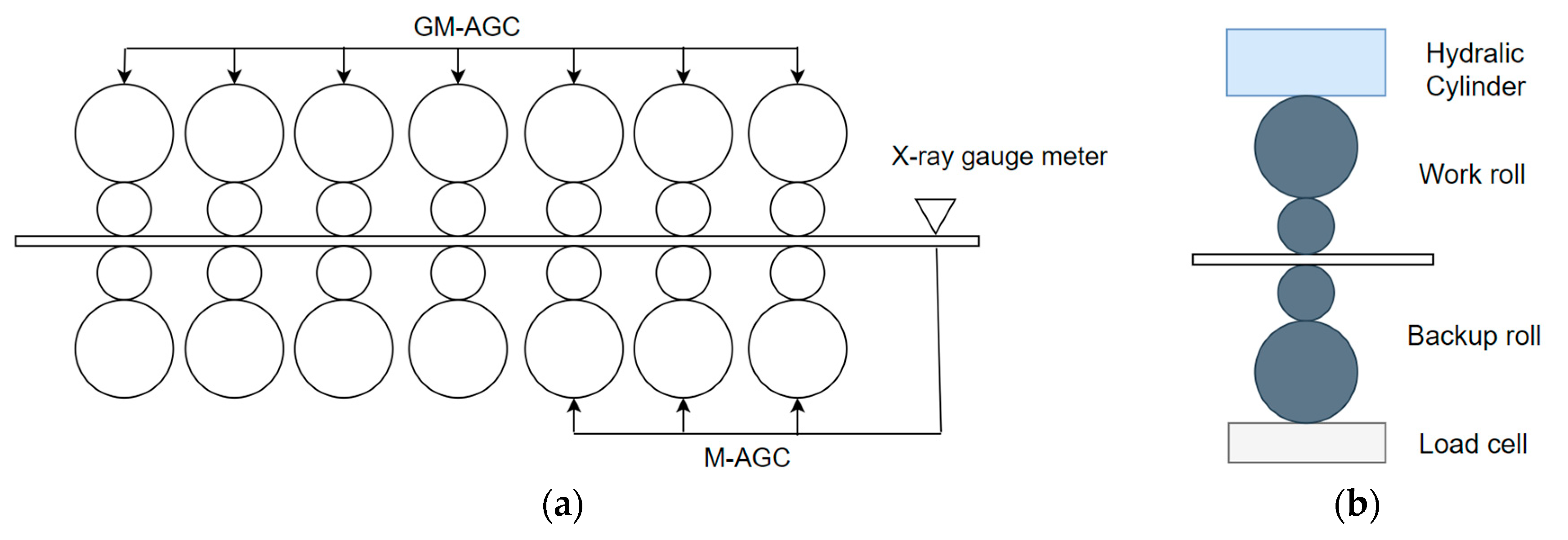
2]. M-AGC uses the measured thickness deviation, which is measured by the X-ray gauge meter located at the exit of the final stand, as feedback to eliminate the strip thickness deviation, which is widely used in modern strip rolling mills. Given the challenging conditions and spatial constraints inherent in hot strip rolling operations, it is impractical to install thickness sensors at every stand. Consequently, a GM-AGC system is implemented at each stand, wherein the gap is adjusted using a calculated thickness derived from a simplified thickness model, rather than direct thickness measurements. Typically, the GM-AGC manipulates all seven stands, and the M-AGC adjusts the last three stands in the finishing mill, as shown in
Figure 1a, which is also the system configuration used in China Steel Corporation (CSC).
The finishing mill comprises seven four-high stands (F1–F7), with each stand equipped with a pair of work rolls and another pair of backup rolls, as shown in
Figure 1b. To provide feedback to the gauge control system, a load cell is positioned at the bottom of the lower backup roll, offering measurements of the rolling force.
In practical experience, the primary sources of thickness errors include the following:
First, it is obvious that increasing the initial setup inaccuracies exacerbates the thickness errors, thereby compromising the stability of the system. Due to the complexity of the production process, occasional occurrences of this scenario are unavoidable. Thus, there is a necessity for more robust control methods to facilitate thickness control under such circumstances.
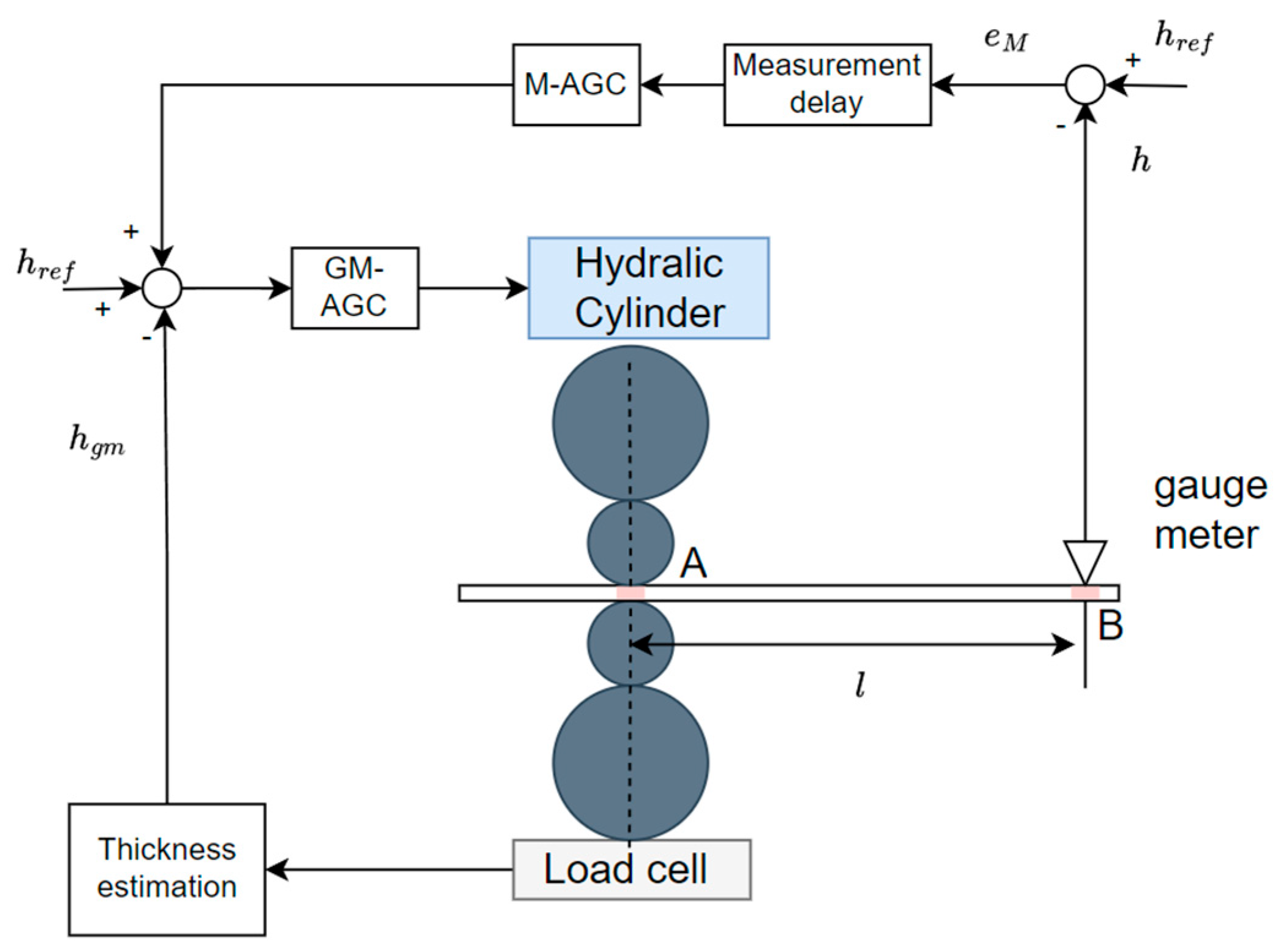
Second, because of the restriction of the milling structure and requirement of maintenance, the gauge meter is installed behind the final stand for strip thickness measurement. As shown in
Figure 2, at point A, the rolling force is measured by the load cell, and then the estimated thickness
can be obtained by the gauge meter equation. Using the estimated thickness as the feedback control is called GM-AGC, and there is no delay time between the actuator and sensing device. However, it is well known that it is difficult for the gauge meter equation to fully describe all rolling behaviors, and there will be discrepancies between the predicted values and the actual thickness. Thus, feedback control using the actual thickness measured by an X-ray gauge meter is required, which is called M-AGC. The true thickness value
is measured by the gauge meter at point B. M-AGC adjusts the roll gap based on the measured thickness, which is more accurate compared to the estimated thickness, to ensure the strip thickness. But it is obvious that the measurement delay exists in the M-AGC system due to the sensing device location. The delay time may deteriorate the accuracy and dynamic characteristics of the control properties, such as the settling time and overshoots.
Third, due to the absence of measuring devices, the primary control at the upstream stands relies on GM-AGC. However, it is well known that it is difficult for GM-AGC to achieve accurate thickness correction due to the system complexities. The material temperature distribution [
3], work roll thermal expansion [
4], and oil lubrication [
5] are factors in the strip thickness. Numerous works have delved into refining the precision of corrections associated with GM-AGC; however, the mutual influence between the upstream and downstream stands has usually been neglected. Additionally, the adjustments to upstream stands by conventional M-AGC are typically implemented through a proportional approach. To ensure a more stabilized rolling process, the upstream stand adjustments are usually constrained to smaller magnitudes. Consequently, the accumulation of thickness errors throughout the rolling process can lead to concentrated corrective adjustments, particularly noticeable at the final stand. In tandem rolling, an escalation in corrective actions corresponds to amplified variations in rolling forces, potentially causing imbalances between the stands. This imbalance in forces can manifest as flatness issues or strip necking problems, highlighting the importance of mitigating force disparities between the stands during rolling operations.
Tandem finishing rolling control is a complex process, involving not only the strong interactions between the thickness and flatness, as mentioned, but also numerous factors that can affect the final quality of the product. The work by [
6] shows the modeling of and interactions among the process variables. Thus, many control strategies have been developed to improve the performance and disturbance rejection for the tandem rolling process. A feedforward controller to compensate for the known disturbances from upstream entities is depicted in [
7]. As demonstrated in [
8], the concept of mass flow control was implemented in the model of a whole tandem mill. In [
9,
10], the strong coupling and complex multivariable relationships among the strip gauge, looper angle, and strip tension in tandem hot rolling were investigated. These studies have pointed out the importance of entry disturbance and the coupling effects in the tandem rolling process. However, research on the interactions among the rolling force, thickness, and shape condition is still relatively rare.
As a result, the aim of this paper is to discuss the interaction between the thickness and shape condition during tandem finishing rolling. Time delay is a critical factor that influences the overall performance in thickness control. In the literature, one of the solutions to the control problem of the time delay system is the Smith predictor (SP) [
11,
12,
13]. It is well known that one condition of the SP is that it needs to know the accurate mathematic model of the control project, and the performance may potentially decrease due to parameter variations. Numerous scholars have utilized and improved upon these constraints, successfully applying them to thickness control. Based on the SP control framework, we present the shape-balanced-type AGC with SP to illustrate how to keep the shape conditions during the thickness control.
Strip flatness is highly complicated, and important factors, such as the thermal crown, roll wear, and rolling force, can affect the shape quality dramatically [
14,
15]. To overcome the limitations of this nonlinear and strong coupling in the process of hot rolling, many recent studies have employed machine learning approaches to predict flatness, aiming to improve the accuracy [
15,
16,
17]. However, it is well known that strip flatness is affected by AGC in the rolling process [
15,
18], and the issue of flatness problems caused by excessive concentrated thickness adjustments in the final stand have rarely been discussed. To this aim, in this paper, we propose shape-balanced automatic gauge control (SB-AGC) for M-AGC, which considers the setup rolling force distribution ratio in the last three downstream stands. The SB-AGC strategy results in a lower rolling force variation at the final stand and consequently improves the strip flatness condition [
19]. Ref. [
20] also showed a M-AGC control strategy applied to a hot finishing mill in an aluminum plant based on the thickness variation distribution. The advantages were eliminating the strip thickness deviation of a finished product faster and improving the correction speed of the strip thickness deviation successfully. The results illustrated that M-AGC, with the concept of force distribution, improved the strip shape conditions. However, the disadvantage was that the greater thickness deviation correction in the upstream stand caused greater variation in the strip shape quality, resulting in an excessive burden on the bending control system during thickness deviation correction.
In addressing this issue, a primary contributing factor might be the greater thickness correction in the upstream stands during the transient response, which may lead to overshoots and oscillation. SB-AGC can ensure a relative balance in the rolling forces between the stands during the steady state, preventing the deterioration of the strip shape condition. But during transient periods, the increased correction from the upstream stands intensifies the transient response, resulting in greater variations in the head-end thickness and longer convergence times. It is important to note that the major focus is on the final thickness response, while the tracking performance between the upstream stands is secondary. Therefore, this work presents an asynchrony shape-balanced automatic gauge control (ASB-AGC), which can overcome the shortcomings of SB-AGC. ASB-AGC achieves a smoother thickness response while maintaining a favorable balance in the rolling force.
The objective of this study was to develop a control algorithm that can keep the good shape condition and thickness performance of a tandem hot strip mill. In this paper, conventional M-AGC is first explained. Then, the improved strategies of SB-AGC and ASB-AGC are discussed. To evaluate the effectiveness of the improved strategies, the simulations in the same rolling conditions are tested based on conventional M-AGC, SB-AGC, and ASB-AGC, respectively. Finally, the rolling force variations, the thickness variations, and the balance of the thickness correction are compared. The simulation results reveal that ASB-AGC and SB-AGC system reasonably redistributed the rolling force to reduce flatness issues. Additionally, we also prove that the developed ASB-AGC framework has smaller overshoots than SB-AGC. Moreover, ASB-AGC improved the correction speed of thickness deviation and reduced the settling time successfully. This not only makes a great contribution to rolling process robustness but also reduces the proportion of strip that needs to be trimmed due to inconsistencies in the head-end thickness, thereby improving the yield and effectively reducing production costs.
The contributions of this studies are listed as follows: (i) the practical issue of rolling forces imbalances is highlighted, and the SB-AGC control strategy is introduced to achieve a balanced distribution of rolling forces; (ii) transient thickness overshoot is analyzed in SB-AGC, and then the ASB-AGC method is proposed for better performance; (iii) the simulation results reveal that the proposed ASB-AGC control strategy has better transient thickness performance than SB-AGC, and a balanced rolling force distribution can also be guaranteed; (iv) the improved efficacy of the rolling process is highlighted following the implementation of the SB-AGC and ASB-AGC algorithms. It is important to emphasize that the proposed control framework was validated by a decrease in flatness irregularities. This reduction in irregularities also translates to a decrease in yield loss, attributed to the reduction in head-end cutoff losses.
2. Control System of Hot Strip Mill
The effect of time delay on AGC is significant; it might cause overshoot or induce instability within the system. In this paper, we focus on a new control method, which is considered the tandem relationship of the mill. First, using the Smith predictor, a time-delay-free model can be obtained. Based on this model, the feasibility of load balance control methods can be explored and simulated. Second, we discuss how to design the control law for each stand under rolling force in the tandem rolling process.
2.1. Automatic Gauge Control in Final Stand
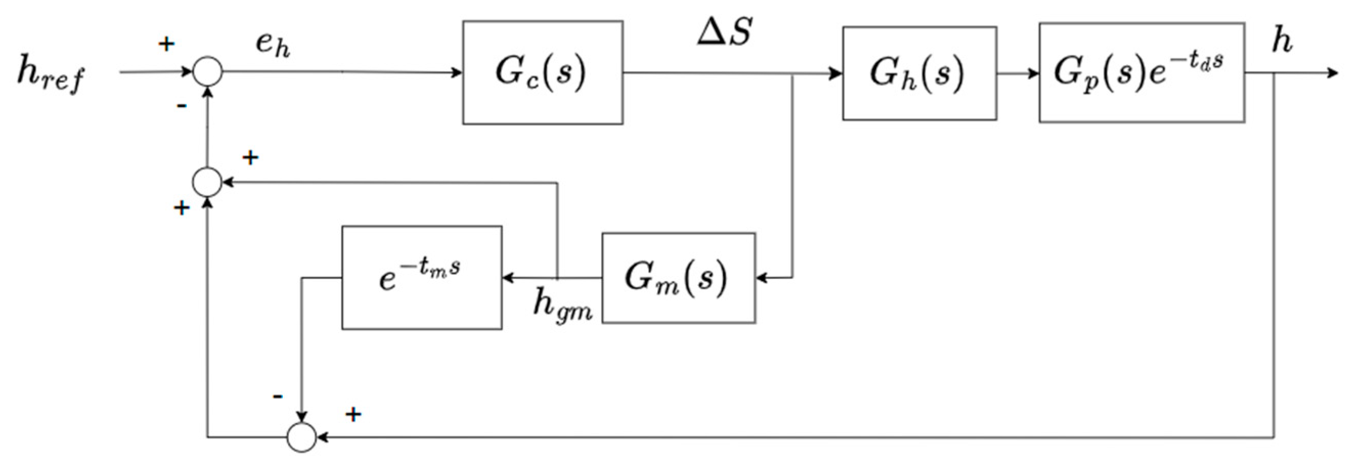
The AGC system, a combination of M-AGC and GM-AGC, is widely used in the steel industry. The final stand is mostly responsible for the thickness accuracy, and the thickness measurement device is installed at a distance behind the final stand. A block diagram of the M-AGC system is shown in
Figure 3. In the figure,
is the primary controller;
is the control command;
is the hydraulic cylinder model;
is the milling model;
is the time delay measurement;
is the thickness reference;
is the real strip thickness measured by the gauge meter.
The closed-loop control system transfer function is shown as
In (1), the time delay part,
, included in the characteristic equation degrades the system’s stability. Thus, the system needs GM-AGC and the Smith predictor to compensate for the time delay effect. A block diagram of M-AGC with GM-AGC and the Smith predictor is shown in
Figure 4, where
is the thickness estimation model,
is the estimate the strip thickness, and
represents the estimated delay time, respectively.
According to the rolling theory, the simplified thickness model called the gauge meter equation can be expressed as follows:
where
is the measured rolling force, and
is the stand stiffness.
When only considering the exit thickness variation [
21], the linear equation describing the rolling force and strip thickness can be expressed as follows:
where
Q is the strip plastic deformation modulus.
Substituting (3) into (2), the milling model can be simplified as
The hydraulic cylinder can be described as a first-order system as follows:
where
represents the time constant of the mill hydraulic cylinder.
In most cases, a proportional and integral (PI) controller will be selected in industry applications. Thus, the thickness controller
can be designed as follows:
Supposing the models are accurate, they give
and
. Then, the closed-loop transfer function of the AGC system can be simplified as
With the Smith predictor, the closed-loop system characteristic equation does not include time delay, and the controller gain can be designed easily using conventional control theory.
2.2. Shape-Balanced Controller Design
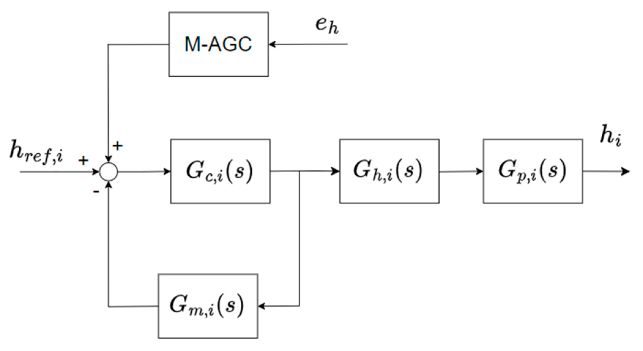
Considering the tandem rolling process, M-AGC not only adjusts the final work roll gap but also the upstream stands. The conditions of the upstream stands will affect the results, increasing the complexities of the hot rolling process. Conventional M-AGC is commonly used in the industry. The correction of the reference thickness at each stand can be designed as shown in (8), and the control structure is shown in
Figure 5.
where
is the number of stands, and
is the transport time from the
ith stand to the gauge meter, which can be calculated using
where
is the distance between the stands,
is the delivery strip velocity,
is the final stand,
is the distance between the final stand and the gauge meter,
is its delivery strip velocity,
is the integral control gain,
is an adjustable control gain, and
is the thickness deviation.
The thickness deviation can be measured by applying
Thus, the final stand thickness correction with the Smith predictor is
The thickness control at the upstream stand also combines M-AGC and GM-AGC. By using the thickness deviation from the final measurement, the upstream stand is given a calculated correction command and integrated with GM-AGC to expedite reaching the target thickness.
For the stability of the rolling process, a smaller control gain is typically chosen for the control at the upstream stand. Additionally, under the same control gain, the correction is almost defined by
. It is obvious that the correction amounts at the upstream stands are significantly lower than at the final stand, leading to dominant thickness correction occurring at the final stand. In this situation, the overload and shape quality will be issues during the rolling process. An example of the thickness correction ratio at each station under the conventional M-AGC strategy is shown in
Figure 6, which shows that the rolling load at F7 fluctuates significantly with conventional M-AGC adjustments. This imbalance in the load ratio between F6 and F7 may lead to plate shape anomalies or necking phenomena.
To solve this issue, the correction of the reference thickness at each stand should take the rolling force into consideration. The incremental form of the rolling force can be expressed as follows:
The deviation in thickness under the influence of the variations in the roll gap and entry thickness can be derived by
The entry thickness is the result of the exit thickness from the upstream stand, that is
In this case, we consider the last three stands of the finishing mill. With the iteration of (13), the last stand thickness deviation can be expressed as follows:
Assuming there is no entry thickness deviation, the relationship between the roll gap and rolling force is as follows:
The change in the rolling force due to the adjustment in the roll gap is proportional to the setup rolling force at each stand, represented as (17):
Substituting (17) into (15) leads to the relationship between the last stand thickness deviation and the upstream rolling forces:
where
is a constant, which can be solved by setting (18) equal to the F7 thickness correction (11), as shown in (19).
Then, the incremental changes in thickness at stand F5 can be derived as (20):
and the incremental changes at stand F6 can be calculated by
Using the measured rolling forces, the thickness correction for the upstream stands are calculated by substituting (19) and (20) for (8). This method is called shape-balanced automatic gauge control (SB-AGC). Obviously, SB-AGC can redistribute the rolling force under load balance considerations. However, it also means that the upstream stand thickness corrections will increase. As mentioned earlier, the thickness error sources, such as time delay and GM-AGC error, exist in the M-AGC system, which deteriorates the dynamic characteristics and stabilities and might cause overshoots. In such a scenario, the upstream stand thickness corrections will also include these overshoots. These overshoots might trigger strip oscillation or hunting, which must be addressed in the rolling mill control loop.
2.3. Asynchronous Shape-Balanced Controller Design
To avoid the aforementioned drawbacks, this paper presents an asynchronous shape-balanced AGC method, named ASB-AGC. The correction amount is fed into a command prefilter, as shown in (22), in which a filter is introduced to attenuate the oscillation and overshoot caused by the final stand.
where the time constant
can be designed as follows:
There are two key factors: one is the parameter , which is the synchronization gain, and the other one is the synchronization rate . The range of is from 0 to 1, where 1 represents a high synchronization rate and, conversely, 0 represents a low synchronization rate. This design allows for convenient adjustments for different steel grades.
The synchronization rate can be adjusted according to the type and thickness of the steel products, in accordance with their product characteristics. Generally, for products with faster rolling speeds, such as harder or thinner products, a higher synchronization rate is used to reflect rapid corrections. For products with slower rolling speeds, reducing the synchronization rate can mitigate overshooting caused by the final mill stand.
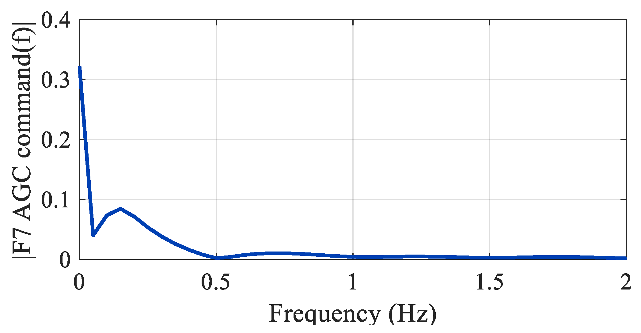
Based on the proposed algorithm, the design goal is to smooth the control command for the upstream stand, which originates from the control command of F7. Generally, the overshoot of a system can be analyzed using the system’s transfer function. However, in tandem rolling mill systems, due to factors such as time delays and variations in rolling forces, obtaining an analytical solution is more challenging. Therefore, by collecting data to analyze the response of the F7 control command and using fast Fourier transform (FFT) analysis, the oscillation frequency distribution range of the system’s overshoot can be determined. This frequency range is used to design the cutoff frequency for the command prefilter, and the synchronization gain can be determined accordingly. In practical applications, we recommend selecting the prefilter cutoff frequency based on the thickness and hardness of the steel strip. The simulation results for different cutoff frequencies are presented in
Section 3.
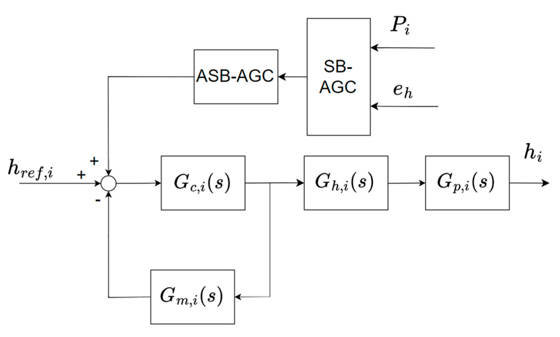
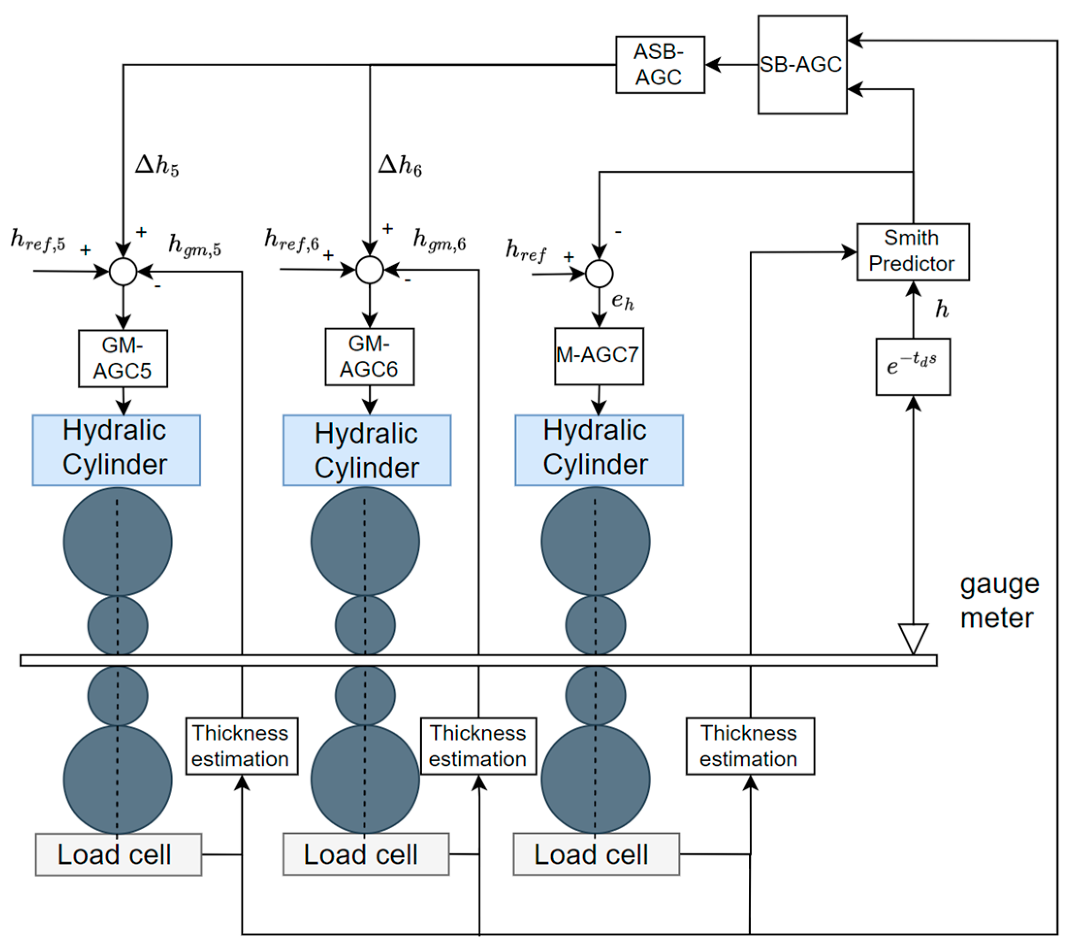
The proposed SB-AGC and ASB-AGC control structure in upstream stands is depicted in
Figure 7, and the overall schematic diagram is shown in
Figure 8. Based on this compensation framework, one can find that the thickness deviation with the measured rolling forces provides the new thickness correction commands, leading to better performance of the thickness response and load balance. The advantages are demonstrated in the next section.
3. Numerical Simulations
Conventional M-AGC with the Smith predictor and SB-AGC and ASB-AGC controllers were compared using MATLAB/Simulink (R2021b) software. The parameters of the simulations are listed in
Table 1. The simulations were carried out as follows. Initially, a strip had an assumed thickness error pass at F5, and the thickness was controlled by GM-AGC with the assumed thickness error. The rolling force calculation was based on the Sims Force model [
22]. It is difficult to design the assumed thickness error due to the complexities of hot mill rolling; especially in the tandem process, the changes in the upstream corrections will affect the thickness error at F7. However, this study set the errors at constant values to illustrate the differences in the control methods.
In the tandem hot rolling process, the upstream exit thickness corresponds to the downstream entry thickness. It was assumed that there was a 1 s delay in the steel strip transmission between F5 and F6. Similarly, a 0.8 s delay between F6 and F7 was applied. After passing through F7, a simulated thickness sensor measured the real thickness of the steel strip after 0.4 s. The time delay was based on the speed setting of the steel strip, with no consideration given to acceleration or deceleration. Strip tensions were assumed to be constant in this simulation.
Based on the mentioned sources of thickness error, an initial setting mismatch of about 0.05 mm was added. Additionally, an assumed GM-AGC thickness error was imposed, and the upstream stands’ adjustment magnitude was determined based on the M-AGC gains (8). Integrating these adjustments with GM-AGC, the thickness control simulation was carried out.
For SB-AGC, the thickness adjustments for F5 and F6 were calculated by (20) and (21); for ASB-AGC, the thickness adjustments were based on SB-AGC with a designed command prefilter (22).
3.1. Simulation Results of Conventional M-AGC and SB-AGC
To show the validity of the proposed algorithm, we present a comparison of the numerical example. First, the simulations by conventional M-AGC with and without the assumed thickness error were executed. The simulation began at F5, where the exit thickness of F5 after a transport delay became the entry thickness of F6. This same process was repeated from F6 to F7. Subsequently, when the strip exited at F7, the thickness errors were detected by the gauge meter, also with a transport delay. This marked the initiation of M-AGC thickness control. Consequently, the simulation results indicate that the responses from F5 to F7 were governed solely by GM-AGC until the strip reached the gauge meter, with M-AGC starting at t = 2.2 s.
Each thickness command is shown in
Figure 9a, which demonstrates that the thickness correction was dominated in F7 when thickness deviation occurred. Moreover, compared to the case without assumed errors, the rolling force at F7 increased dramatically to adjust the thickness, as shown in
Figure 9b. The simulation highlights that in practical applications, the issue of rolling force imbalance can easily occur.
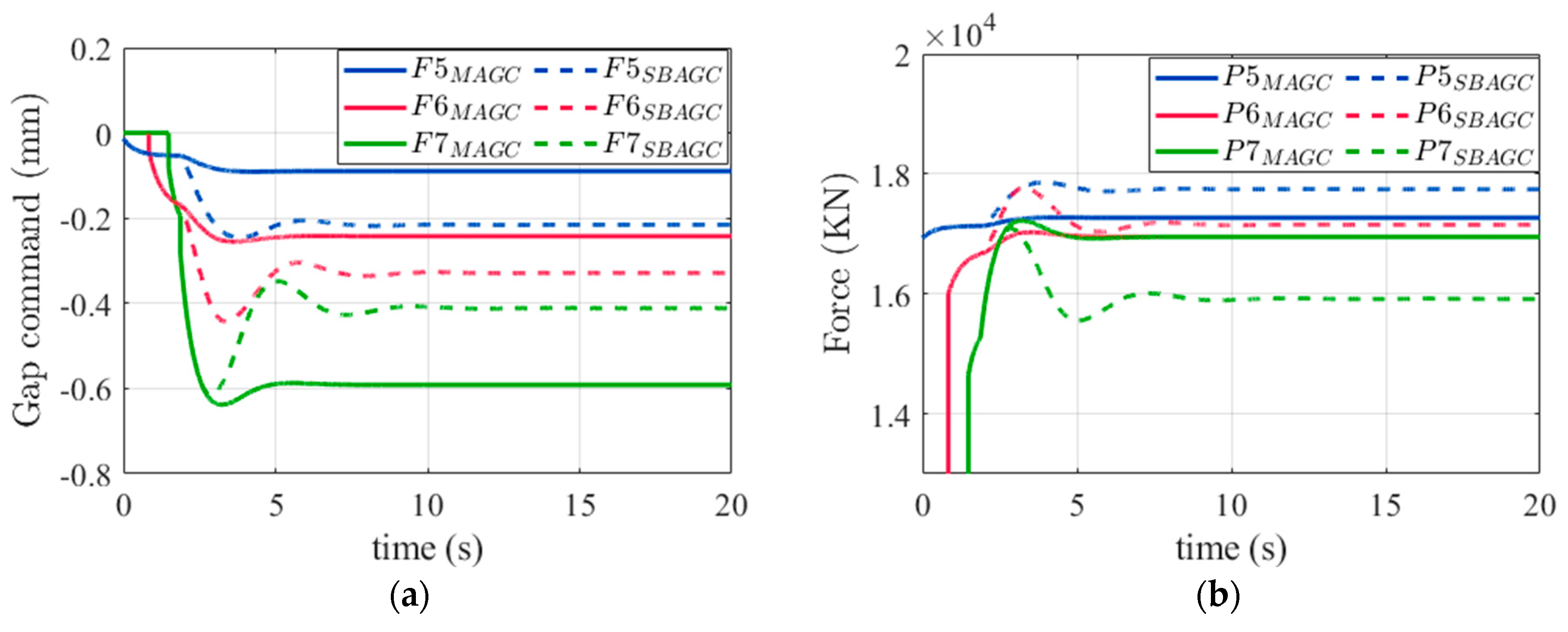
The results utilizing SB-AGC with the assumed thickness errors are also presented. The differences in the thickness corrections are shown in
Figure 10a. They demonstrate that the upstream stands adjustments were rebalanced by the proposed algorithm. In contrast to conventional M-AGC, the adjustments at the upstream stands were redistributed by considering the actual rolling force. In
Figure 10b, it can be observed that the increase in the rolling force at F7 was more gradual, resulting in a more rational distribution of thickness adjustments to the upstream stands. In
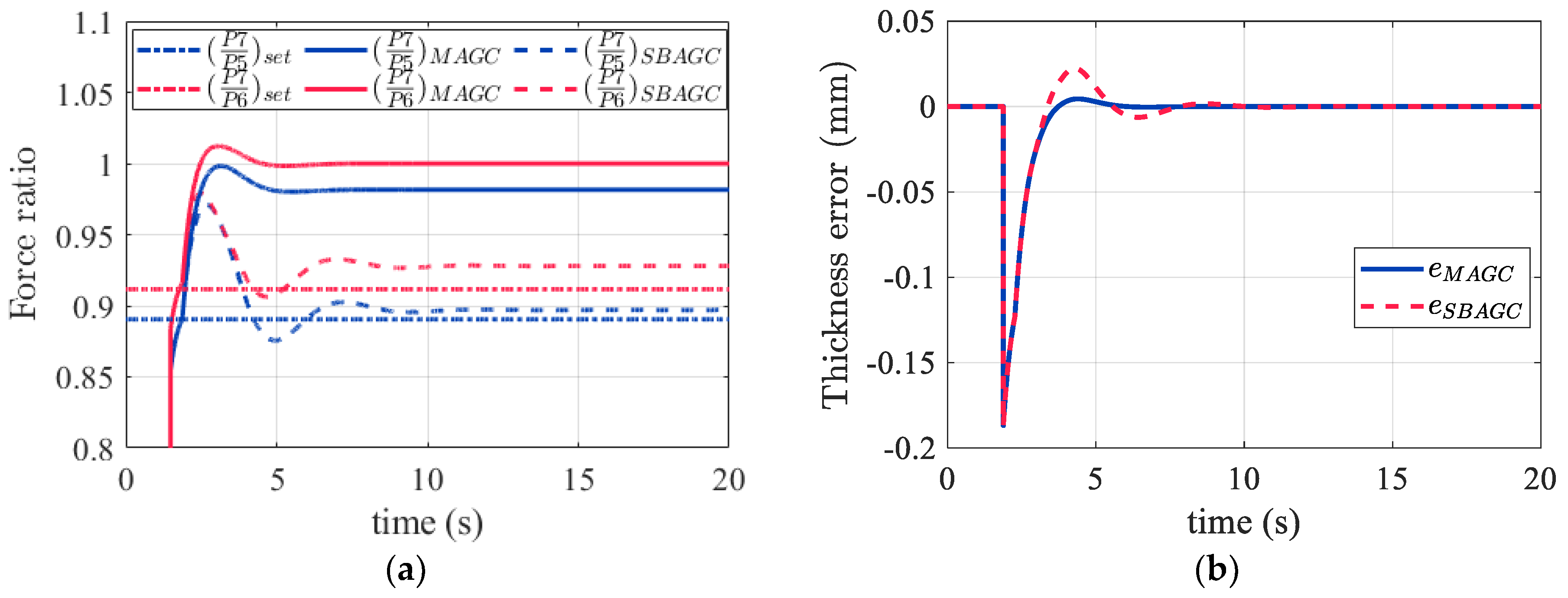
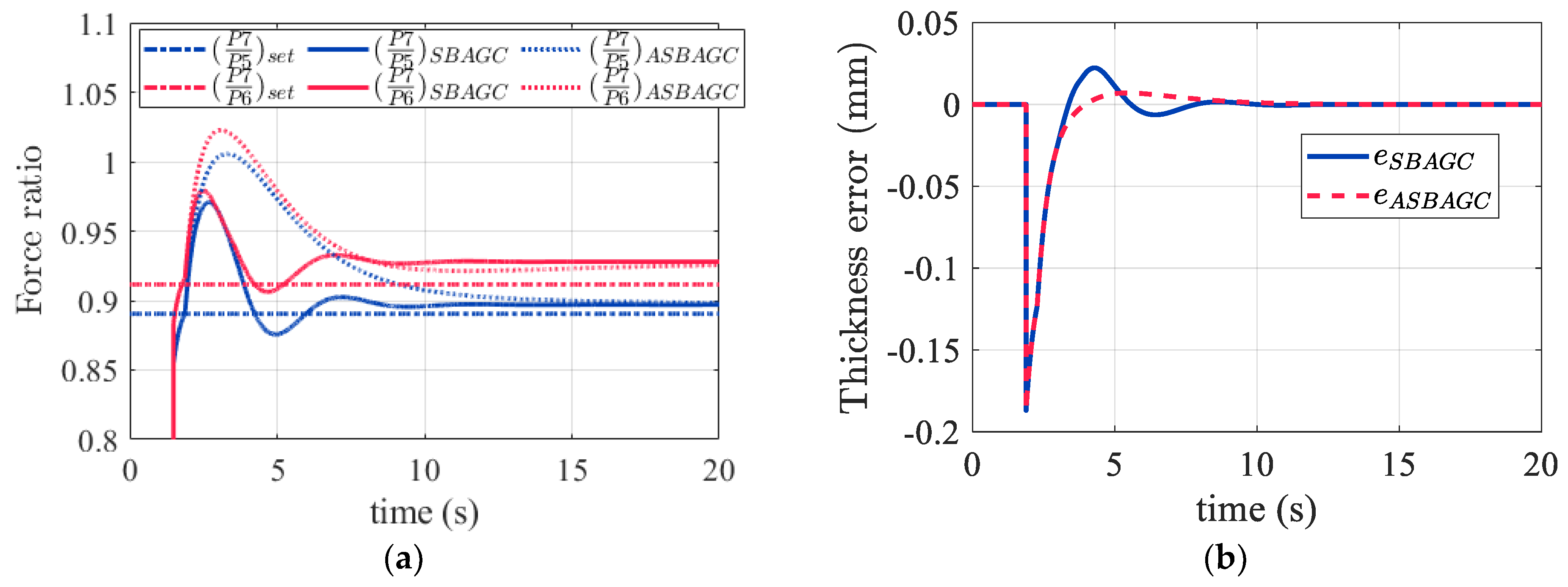
Figure 11a, SB-AGC managed to keep the rolling force close to the setting ratio, where the setting force ratio was calculated by the rolling force without the assumed thickness error in the steady state.
Figure 11b shows the thickness error measured by the gauge meter. It illustrates the drawbacks of SB-AGC, which is that the control algorithm enlarged the thickness correction of the upstream stands, and higher oscillation occurred during the transient period.
3.2. Simulation Results of ASB-AGC
First, the cutoff frequency
for the ASB-AGC command prefilter needed to be determined. To this aim, simulation data from the F7 command were collected and analyzed by performing FFT analysis. An FFT example is shown in
Figure 12, where the oscillation frequency
distribution range was approximately 0.1 to 0.2 Hz for the collected data. These results are related to the closed-loop transfer function of the milling system, and different control gains or system parameters influenced the results. The
range can be used as a basis for the prefilter design, and therefore, time constant
can be determined. The following illustrates the effects of different time constants on the thickness response and upstream control command.
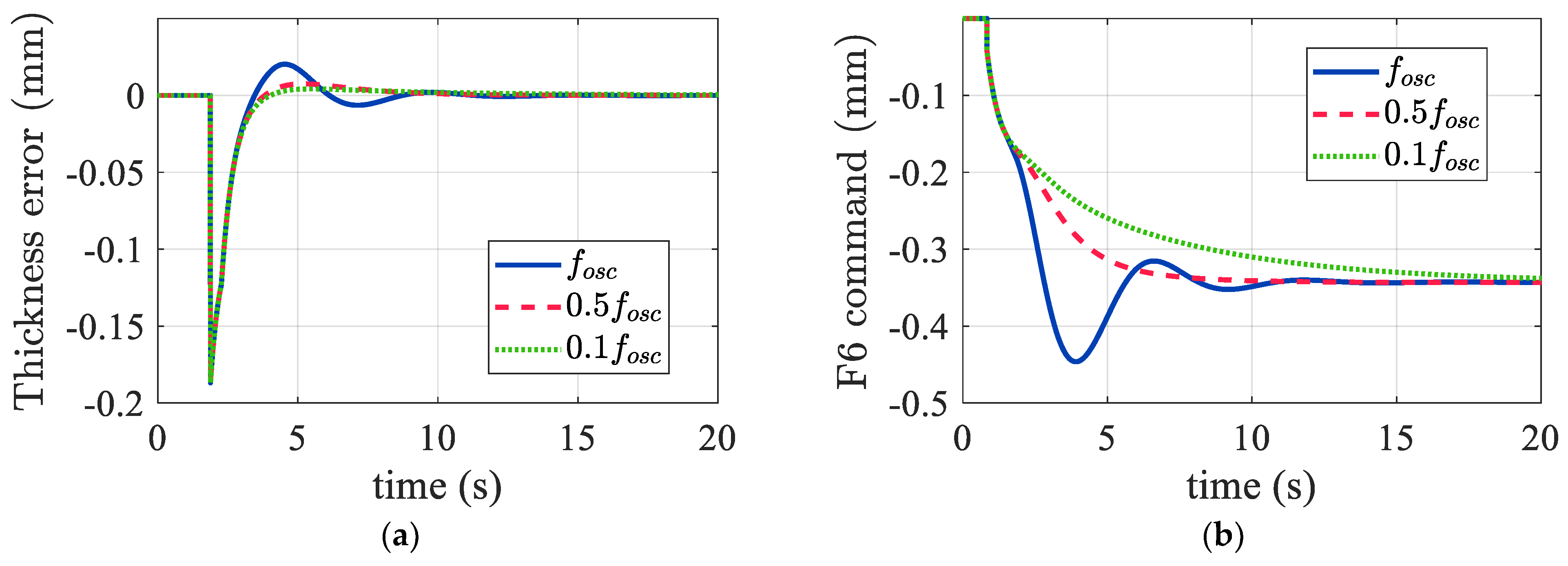
Figure 13a shows the results using 0.1
, 0.5
, and
as the command prefilter cutoff frequencies. It is evident that the suppression of thickness overshoot was more effective between 0.1
and 0.5
. Moreover, the upstream thickness commands are illustrated in
Figure 13b, which also demonstrates the effects of incorporating the command prefilter. As a consequence, in the following comparison simulation, we selected the oscillation frequency
as 0.15 Hz and chose 0.5
as the cutoff frequency. Consequently,
was obtained for both the F5 and F6 stands.
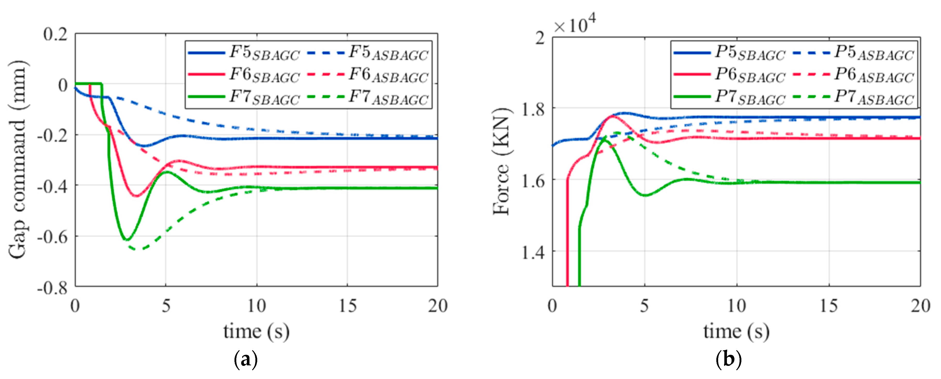
With the same setting conditions as in
Section 3.1, a comparison of the thickness corrections between SB-AGC and ASB-AGC is shown in
Figure 14a. It demonstrates that the correction commands of ASB-AGC at F5 and F6 were smoother than those of SB-AGC. However, it also led to ASB-AGC generating higher peaks in the rolling force at F7, as shown in
Figure 14b. As shown in
Figure 15a, the force ratio still kept the relative balance of the force ratio by ASB-AGC during the steady state, but obviously the force ratio was higher than that of SB-AGC during the transient response. The reason is that the reduction in the correction amount at the upstream stands caused F7 to bear a heavier load during the transient response. Therefore, the ASB-AGC command prefilter should be designed depending on the product characteristic. Most importantly, the thickness error response, shown in
Figure 15b, indicates that SB-AGC can achieve the goal of reducing overshoot and oscillation. The gentler thickness response contributes to the greater robustness of the rolling process and has advantages such as reducing the proportion of the head-end cutoff length.
4. Application Results
In this section, the results of applying the proposed methods in the NO. 1 HSM at CSC are presented. The analysis and simulations have demonstrated the feasibility and effectiveness. However, in practical applications, utilizing the Smith predictor may lead to challenges with inaccurate parameter estimation. Therefore, the proposed SB-AGC and ASB-AGC tactics were applied to the thickness control with integral-type M-AGC.
To validate the proposed algorithm, a total of four experimental processes were designed, as shown in
Figure 16. In the SB-AGC algorithm validation, an analysis was conducted on the products with a thickness greater than 2.3 mm, regardless of the steel grade. By collecting the maximum correction amounts for F7 from 3000 coils each for M-AGC and SB-AGC, the statistical results show that the proportion of corrections exceeding 0.2 mm accounted for 21.70%, while this proportion decreased to 2.02% with the use of SB-AGC. These results clearly demonstrate that the issue of rolling force and correction amounts being concentrated in F7 were effectively improved.
SB-AGC rolling force and flatness analysis further selected the use of 1.4 mm thin sheet products, which are generally considered to have higher quality requirements. This demonstrates that SB-AGC has the capability to be applied to various product sizes and steel grades.
In this part, two cycles (five pieces per cycle) of 1.4 mm gauge strips with the same final target dimensions and steel grade were tested to compare the performance of conventional M-AGC and SB-AGC. The average rolling forces were calculated at two time intervals, 0–0.5 s (t1) and 4–4.5 s (t2), to illustrate the M-AGC effects. As shown in
Figure 17a, the rolling force difference at F7 by conventional M-AGC was significantly larger than that at F5 and F6. On the other hand, the rolling force difference at F7 decreased to 154 kN by using SB-AGC, while the rolling force differences at F5 and F6 show slight increases with SB-AGC.
The flatness index units were also calculated using M-AGC and SB-AGC and compared, as shown in
Figure 17b. Clearly, using SB-AGC resulted in better shape variations. The results obtained align well with the analysis presented in this paper. The control algorithm overcame the concentration of thickness adjustments at F7 while rationalizing the distribution of the rolling force, thereby maintaining a better strip shape condition. More details of the SB-AGC implementation results are shown in [
19].
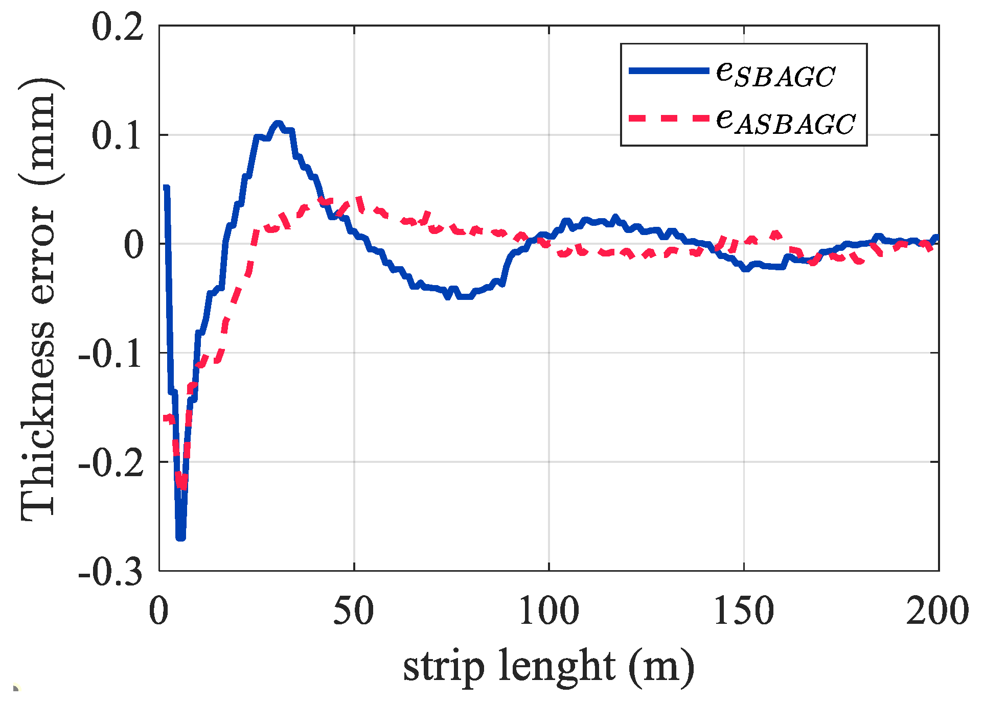
To validate the ASB-AGC transient response, we designed experiments to compare the SB-AGC and ASBAGC thickness responses at the exit of F7, with the same specification of a 2.3 mm gauge strip. Due to the characteristics of SB-AGC, the thickness transient response is prone to overshoot, as shown by the blue line in
Figure 18. However, after incorporating ASB-AGC, the overshoot and oscillation of the final thickness were significantly reduced by about 50% in this case, as shown by the red line in
Figure 18. These results are consistent with the theoretical expectations. The addition of the command prefilter effectively reduced the head-end correction amount, thereby suppressing the magnitude of overshoot oscillations.
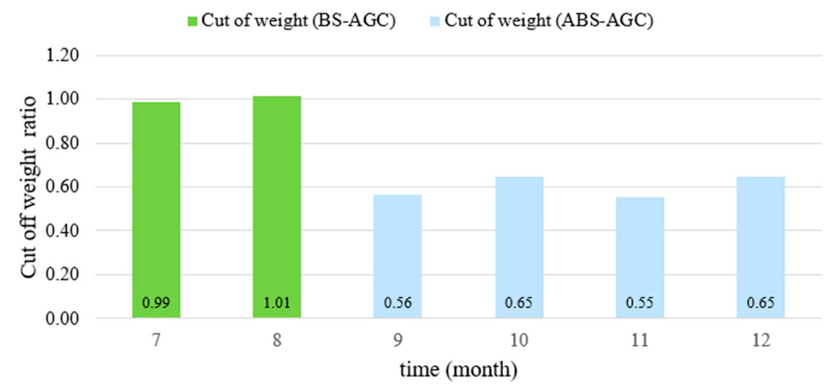
Finally, analysis of the ASB-AGC cutoff weight was conducted, during which the head-end cutoff amounts for all steel grades produced in the NO. 1 HSM at CSC were statistically analyzed. The annual production capacity of NO. 1 HSM is 4 million tons, with an average monthly capacity of approximately 300,000 tons. The monthly actual head-end cutoff weight data over a period of six months in 2022 are shown in
Figure 19. The average of the total SB-AGC cutoff weight was taken as the baseline, and the ratio of the cutoff weight amount for each month to this average amount was used as the cutoff weight ratio. The results reveal a significant downward trend in cutoff losses, which confirms the effectiveness of the proposed method.
The validation processes were sequential. First, we validated the correctness of the SB-AGC algorithm and applied it to steel grades that require higher dimensional accuracy, achieving results consistent with the theoretical predictions in both shape and rolling force distribution. Additionally, the thickness transient response in ASB-AGC was experimentally confirmed to effectively reduce the magnitude of overshoot. The monthly cutoff amounts further demonstrated ASB-AGC’s contribution to the production capacity.
