Abstract
The flux switching permanent magnet (FSPM) motor is a stator permanent magnet motor. The typical FSPM motor is doubly salient, which generates torque ripple and affects the rotation smoothness. In this paper, the influence of salient pole geometric sizes on motor torque performance is studied to reduce motor torque ripple and improve motor torque density. First, three indicators are defined to present the motor torque characters, including the average torque, torque ripple, and the volume of permanent magnet material usage. Then, the model of salient pole geometric sizes function to the three indicators is created. With this model, the optimal solution is obtained by the multi-objective numerical optimization. Based on the optimized results, the rotor shape is refined and analyzed as the supplementary to reduce the torque ripple further. Finally, the results show that the optimization procedure in this paper can effectively weaken the torque ripple, reduce the permanent magnet material usage, and improve the average output torque of the motor. Based on the optimized data, the prototype machine is built to verify the analysis results and prove the feasibility of this research.
1. Introduction
In the area of transmission, direct-driven motors are commonly used due to their characteristics of high precision and quicker dynamic response [1,2]. Unlike the drive structure of the leading screw and reducer, which can disperse stresses by the mechanical structure, the load of the direct drive motor is completely supported by the electromagnetic torque of the motor. So, the windings require a lot of current to generate torque, which also makes a lot of heat. Therefore, the direct drive motor usually uses a water jacket, slot cooling method, etc., to cool the motor stator [3]. Due to motor rotor structural constraints, its heat dissipation performance is usually inferior to that of the stator. The heat of the rotor can usually only be cooled by the air inside the motor, and the cooling efficiency is poor. Most direct drive motors have permanent magnets installed in the rotor, which increases the risk of demagnetization of permanent magnets at high temperatures. Figure 1 shows the FSPM motor configuration. Its permanent magnets are installed in the stator [4,5,6]. That makes the permanent magnet easier to cool during a motor-heavy load.
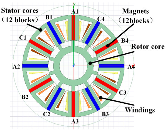
Figure 1.
The section of a 12/10 pole FSPM motor.
However, the FSPM motor has some characteristics that limit its application. The FSPM motor has doubly salient poles, which obviously lead to torque ripple [7,8]. Such characteristics are apparently unfavorable for the requirements of high precision and high dynamic response. It is precisely because of the characteristics of the FSPM motor that many researchers have contributed a lot of work to analyzing the torque ripple of the FSPM motor.
Some researchers focus on the current excitation. In [9], various sources of salient rotors with modular rotor FSPM are compared, and their average torque and cogging torque are analyzed. Some researchers proposed new structures to improve the torque ripple of FSPM. In [10], the authors propose that the cogging torque of flux-switching transverse flux permanent magnet machine is significantly influenced by the ratios of stator and rotor core circumferential widths to pole pitch. In [8], the authors study the torque ripple of FSPM and point out that the torque harmonics are generated by the interaction between the radial and tangential air gap harmonics. They proposed a V-shape permanent magnet that improves the air gap harmonics effectively. In [11], an H-type FSPM linear generator was proposed. The Taguchi optimization approach was used to reduce the force ripple and increase the average thrust force and efficiency. In [12], the authors proposed a new design approach that improves the E-shaped FSPM linear motor to reduce the force ripple. In [13], the authors proposed a novel consequent pole E-core stator FSPM machine that reduces stator flux linkage and torque ripples. In [14], the skewed slot of the rotor is designed to optimize the EMF harmonic character and cogging torque. In [15], a magnetic flux barrier is designed in the rotor to improve the performance of FSPM including the torque ripple. In addition to structural design methods, some researchers also study the control algorithm to improve the torque performance [16]. Some researchers focus on the basic size change in the performance of motors. In [17], the rotor pole width was studied to minimize back-EMF harmonics. In [18], the stator pole shape was mainly studied to optimize the flux linkage, back EMF, and cogging torque. In [19], different coil group sets and shifting rotor teeth were studied to optimize the back-EMF waveform. Ref. [20] proposed two types of rotor configurations and optimized the cogging torque with multiple factors. Ref. [21] studied the dimensions of permanent magnet and rotor teeth to optimize the average torque and cogging torque.
In general, the methods to suppress the output torque ripple of FSPM motors mainly focus on the optimization of new structures. Inspired by these studies, the main factors to affect the torque ripple are salient pole dimensions at the air gap. These shape dimensions are related to several parameters. Therefore, this paper focuses on the rotor and stator poles combined optimization to reduce the torque ripple and promote the average torque. In considering more detailed features, the rotor shape is refined and its effect on the torque characteristics of the motor is studied to improve the motor further.
2. The Basis of the FSPM Motor
A topology of the 12-stator/10-rotor poles FSPM motor axial section is shown in Figure 1. Its axial length is 67 mm. The windings are separated into three groups (A, B, and C). Each group has four parts. Each part has 90 turns of the conductor. With the motor running, the three groups flow AC current with a 120° phase difference. The permanent magnets at A1, C1, B2, A3, C3, and B4 are magnetized clockwise tangentially. The other magnets are magnetized anti-clockwise tangentially.
In order to describe the geometric dimensions of the motor, the section of the FSPM motor and the specific geometric parameters are shown in Figure 2. The geometric data sheet is shown in Table 1.
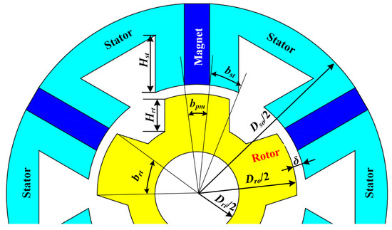
Figure 2.
The dimensional parameters of FSPM.

Table 1.
Geometric size of the FSPM motor.
With the relative rotation between the rotor and the stator, the flux in windings changes. Because of the doubly salient pole of the FSPM motor, the reluctance of its magnetic circuit is not uniform, which leads to the harmonic components in motor torque and affects the purity of torque output. The parameters in Table 1 all have a certain influence on the magnetic circuit of the motor. However, the parameter that has the most significant effect on the torque ripple is the salient pole dimensions at the air gap bst, brt, and bpm, which influence the motor winding flux dynamically. Then, the specific parameters are analyzed by FEM in the next section.
3. Analysis of Salient Pole Dimensions
In this part, the transient analysis is carried out on the ANSYS Electronic 2020R1 software. The rotor speed is set at 300 rpm. The constant q-axis current excitation is applied in the simulation. The phase current excitations are a sine function of rotor position. The stator core material is DW465. The rotor is made of C10 steel. The permanent magnet material is N35H and the coils are copper.
The motor salient pole width is mainly determined by bst, brt, and bpm. In order to study the effect of parameter variation on motor torque output characteristics, an FEM parametric model is built according to Table 1. The three main parameters are analyzed in detail separately. To compare the effects of parameter changes, the average value of torque and the peak-to-peak value of torque ripple are worked out to present the characteristics of motor output.
3.1. Effect of bpm on Motor Output Torque
In the FEM model, the initial dimensions of the motor keep constant as Table 1. The angle of the motor permanent magnet bpm is set to range from 3° to 10.5° with steps of 0.5°. The average value of motor torque and its ripple peak-to-peak value at the winding excitation current from 0 A to 1.8 A are shown in Figure 3. The exciting current amplitude has little effect on the peak-to-peak values of torque ripple. So, the results under 0 A current excitation are used to present the torque ripple feature.
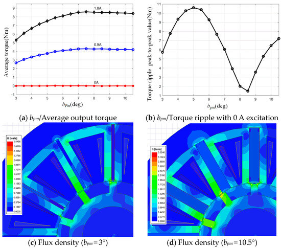
Figure 3.
bpm and the torque performance.
The output average torque of the motor tends to increase as the angle of the permanent magnets increases. The increasing of the permanent magnet angle promotes the magnetic potential; meanwhile, the reluctance of the entire magnetic circuit does not change, and the total flux increases. Thus, the output torque of the motor can be increased with the same winding current excitation. According to the data in Figure 3a, the 250% increase in permanent magnet angle yields only a 63.5% increase in output torque. When the permanent magnet angle is greater than 7.5°, the magnetic circuit saturates (Figure 3d); the magnetic potential of the permanent magnet is excess. Therefore, it is appropriate to choose a permanent magnet angle range from 4.5° to 7.5° for further optimization and the reduction in permanent magnet material used. Figure 3b expresses the influence of torque ripple peak-to-peak value with bpm changes. It can be seen from the figure that the change in bpm has a significant impact on the torque ripple. The change in bpm angle will cause the variation in flux linkage during rotation that leads to the change in torque harmonics. The torque harmonics generate torque ripple. The change in bpm essentially makes the whole stator salient pole angle change synchronously. Therefore, in practice, this result is only for reference, and it is also necessary to find a method to reduce torque ripple by combining the multi-parameter joint together.
3.2. Effect of brt on Motor Performance
The rotor salient pole angle is one of the important parameters of the motor rotor. In the FEM model, the initial dimensions of the motor are kept constant as Table 1. The motor rotor salient pole angle brt ranges from 6° to 13.5° with a step of 0.5°. The torque performance at the winding excitation current is from 0 A to 1.8 A, as shown in Figure 4.
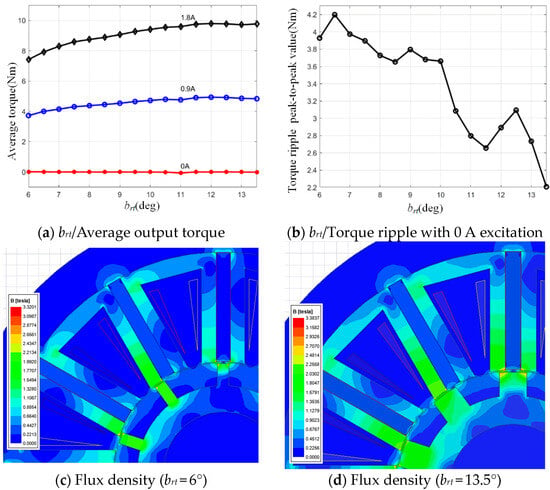
Figure 4.
brt and the torque performance.
From Figure 4a, the motor output torque increases with the increases in rotor salient pole angle. So, as the flux increases, the motor output torque increases too. From Figure 4b, the torque ripple of the motor decreases obviously as the brt increases. The more cross-sectional area of the magnetic circuit brings smooth magnetic flux, which leads the fewer harmonic components in motor torque. The motor’s average torque tends to be leveled off when the brt is larger than 12°. According to the above, it is appropriate to choose the rotor salient pole angle from 10.5° to 12° to carry out further optimization.
3.3. Effect of bst on Motor Performance
The two bst plus one bpm construct a stator salient pole as Figure 1 shows. In the FEM model, the initial dimensions of the motor keep constant as Table 1. The bst sets range from 4.5° to 10.5° in the step of 0.5°. The average motor torque and its ripple peak-to-peak value at the winding current excitation from 0 A to 1.8 A are shown in Figure 5.
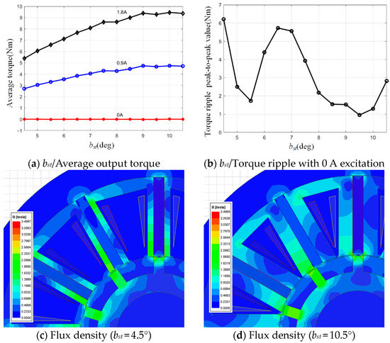
Figure 5.
The bst and the torque performance.
From Figure 5, the average torque of the motor rises with the bst increases. The increase in bst increases the cross-sectional area of flux flow at the air gap, which improves the winding magnetic flux and also enhances the motor output torque. Its principle is similar to the brt. However, due to the fixed brt, the magnetic flux is limited. The motor torque ripple is sensitive to the bst, and there are two minimum value of torque ripple in the tested range. The value of torque ripple shows the amplitude of harmonic components in the torque; it contains the information of flux changes during rotation. When bst is near 9.5°, the motor has the greater average torque output, so it is appropriate to choose a stator tooth angle of 8° to 10° for the further optimization.
The three parameters brt, bst, and bpm are coupled and affected by the reluctance during rotation. It is difficult to obtain accurate optimal solution by single parameter optimization, so it is necessary to conduct coupling optimization using these three parameters.
4. Motor Salient Pole Parameter Coupling Optimization
Multi parameters and multi goals optimization is a typical question in industrial aera. Response Surface Methodology (RSM) is a statistical processing technique based on mathematical and statistical theory for modeling and analyzing multivariate problems. It utilizes the display response surface function to fit a real complex function and converts the response objective of a complex implicit function into a simple explicit function. In order to obtain a more accurate function, the response surface function expressed by a quadratic polynomial containing a cross term is usually used, as follows:
where xi is the significant factor in this model and brt, bst, bpm, β, and ε are function coefficients. Their values are obtained by experiment design, FEM solving, and equation fitting. Yi stands for motor performance indicators. In this part, three indicators are created to evaluate motor performance. The first is the average torque T of the motor. The second indicator is Sri. That is the ratio of the motor torque ripple (peak-to-peak value) to the average value of the motor output torque. The Sri provides a relatively comprehensive evaluation of motor torque ripple. The third indicator is Spm. That is the ratio of the average motor output torque T to the bpm. Obviously, the higher the Spm, the less permanent the magnet usage at the same torque output. To make the indicators on the same order of magnitude, Sri multiplies 10 and Spm multiplies 10−3. The variable factor level is shown in Table 2.

Table 2.
Variable factor level.
In total, 13 test points are constructed by Box–Behnken designs according to design variables, and the response results are solved by FEM. The data are shown in Table 3. After the fitting of the model, three response surface models are established as Equation (2).

Table 3.
Box–Behnken design scheme and results.
Analysis of variance on the model shows that the regression equations of T and Sri reach high significance (model p < 0.0001); the regression equation of Spm reaches significance. The determination coefficient R2 of T and Sri are 0.9978 and 0.9999, which indicates the efficiency and accuracy of the fitted model. The R2 of Spm is greater than 0.9, which indicates that 90% of the variability of the experimental data could be explained by this model. Three regression models shown in Figure 6 fit well with the FEM data, and are able to accurately predict the three response indexes T, Sri, and Spm.
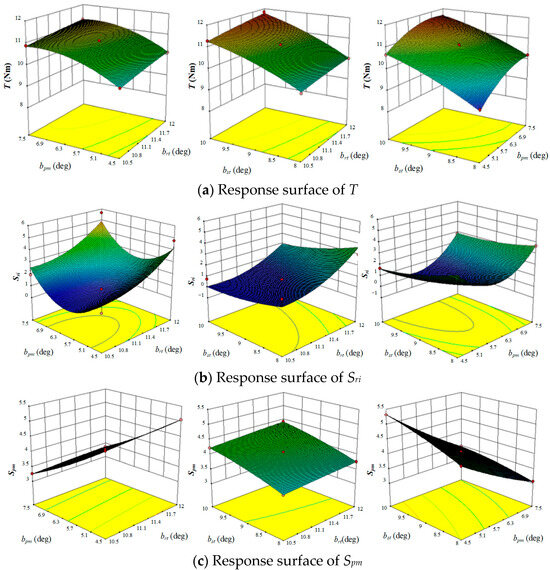
Figure 6.
Response surfaces of T, Sri, and Spm.
The response surfaces are shown in Figure 6. However, the factor values of maximum T, minimal Sri, and minimal Spm cannot be obtained at the same time. Therefore, the multi-objective optimization of the response surface model is carried out by using the trust region method in the numerical optimization method, and the basic form of the trust region is
where k is the iteration point, mk is the approximation model, g(k) is the goal function value at k, Bk is the Hesse matrix or its approximation, is the trust region, and p is the residual of iteration. Multi-objective optimization problems may have interactions between the design variables and between the objectives; it is hard to find a set of design variables to make all the objectives optimal at the same time. Sometimes, this constitutes only a compromise treatment. After comprehensive comparison, the optimal parameter sets and their solution are shown in Table 4.

Table 4.
Optimal factor combination.
The optimal parameters are imported to the FEM model. Its solution is compared with the response surface model prediction in Table 5.

Table 5.
Comparison between the response surface model prediction and the FEM simulation.
From Table 5, the response surface model prediction basically matches the FEM simulation, which proved the feasibility of the multi-objective optimization in this paper.
After optimization, the average torque has been obviously promoted, and the torque ripple has also decreased. The previous optimization basically determined the effect of the main magnetic circuit on the motor performance. However, other parts in the magnetic circuit still have effects on the motor performance. Then, the shape of the rotor salient pole is refined to explore the way to reduce torque ripple further.
5. The Rotor Salient Pole Shape and the Torque Characteristic
The shape of the rotor salient pole refines into the structure shown in Figure 7. The rotor salient pole top arc height Drt and rotor salient pole side angle Art are introduced to explore the possibility of reducing the torque ripple.
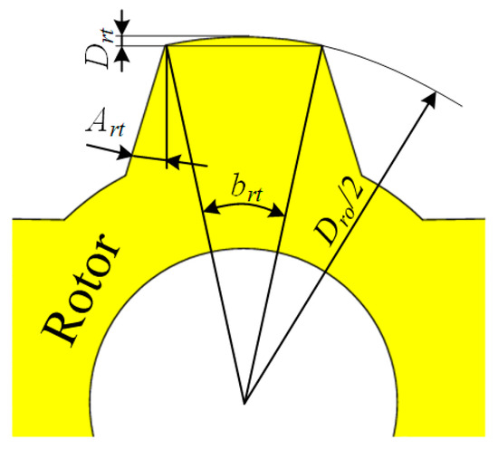
Figure 7.
Art and Drt in the rotor salient pole.
The brt, bst, and bpm affect the flux in the air gap in parallel. So, the coupling analysis is needed for these three parameters. The Art and Drt affect the flux mainly in the rotor. They are like components connected in series on the magnetic circuit. Therefore, the optimization of these two parameters can be carried out independently, without considering the coupling effect.
The Art can slightly change the flux. Too big of an Art may reduce the flux due to the equivalent reduction in rotor salient pole height. In the FEM model, the initial dimensions of the motor are the values after optimization in Section 4. The Drt sets to 0 mm in this analysis. The Art ranges from 0° to 20° with steps of 2°. The torque performance at the winding excitation current from 0 A to 1.8 A is shown in Figure 8.
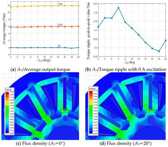
Figure 8.
The Art and the torque performance.
From Figure 8, the Art has little effect on the average output torque. With the Art increases the average torque slightly rises. The change in Art can slightly change the air gap shape, which leads to the variation in torque ripple amplitude. That makes the flux harmonic change. The torque ripple gets the lowest value when Art is at 18°. So, the Art value was determined as 18° in practice finally.
The Drt affects the air gap length in the area of the rotor salient pole. Its change may bring the torque harmonic variation and then affect the torque ripple. In the FEM model, the initial dimensions of the motor are the values after optimization in Section 4. The Art sets to 18° in this analysis. The Drt ranges from −0.3 mm to 0.6 mm with a step of 0.1 mm. The torque performance at the winding excitation current is from 0 A to 1.8 A, as shown in Figure 9.
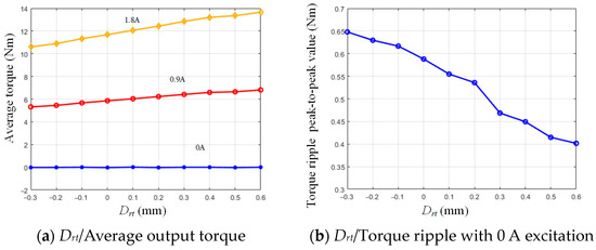
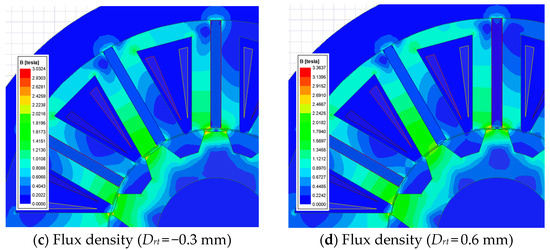
Figure 9.
The Drt and the torque performance.
The increase in Drt substantially reduces the length of the air gap, and it will promote the average torque theoretically. From Figure 9, the results proved this point. With the increase in Drt, the distance between the rotor and stator pole is uniform. That makes the amplitude of harmonic components trend downward. But, the Drt is restricted by the mechanical structure. So, the Drt finally sets to 0.5 mm. This dimension is 0.25 mm longer in the radial direction than the outside circle of the rotor. That means the minimal air gap is 0.75 mm at the center line of the rotor salient pole.
Finally, the motor dimension data are determined and the promotion of performance is evident after optimization. The comparison is shown in Table 6 and the flux density is shown in Figure 10. The AVG torque stands for average torque and the angle of PM presents the volume of permanent magnet usage.

Table 6.
Output characters before/after optimization.
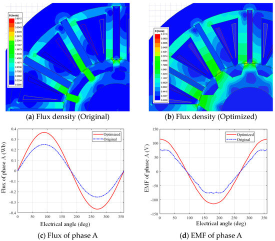
Figure 10.
The comparison between the original and optimized motor.
The torque characteristics before and after optimization in one electrical period are shown in Figure 11.
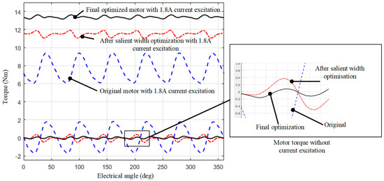
Figure 11.
The torque characteristics before and after optimization in one electrical cycle.
6. Experiment
According to the optimized FSPM motor geometric sizes data, a prototype was built to verify the performance. The stator and rotor are shown in Figure 12.
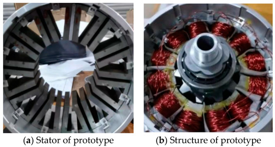
Figure 12.
The prototype of the motor.
A resolver is installed at the end of the motor axis to monitor the rotary angle. From this sensor, the rotor position is easy to obtain for the vector voltage control. This motor is installed on a motor test bed as Figure 13 shows. The test bed consists of a torque/speed sensor, magnetic powder clutch, servo motor, and data acquisition devices. The magnetic powder clutch can be replaced by a magnetic powder brake if the test is needed. The motor is driven by a synchronous motor driver, which uses the SVPWM method to drive the motor.
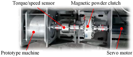
Figure 13.
Motor test bed.
6.1. The No-Load EMF, Speed, and Torque Test
In the no-load EMF test, the magnetic powder clutch is set as the connector between the prototype and the servo motor. The servo motor speed is set at 300 rpm, the phase A’s EMF of FEM result and experiment test are shown in Figure 14.
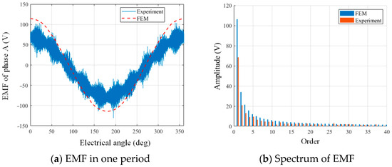
Figure 14.
No-load EMF test.
From Figure 14, the waveform calculated by the FEM is in good agreement with the experimental results in the low-frequency range. The amplitude of the measured waveform is slightly lower than that of the FEM. That is probably due to the loss of the magnetic circuit. In addition, the waveform measured by the experiment also contains a large number of 10 times harmonic components. Since the motor is 12/10 poles, the phase difference between the adjacent rotor pole and to stator pole is 1/5 period. During the rotation, the absolute flux value changes two times in one period. This makes the motor become a rotating transformer. High-frequency noise excitation makes the output signal have the high-frequency noise enveloped by 10 times the period signal.
In the speed test, the magnetic powder clutch disengages. The controller reference speed values set range from 0 to 500 rpm with a step of 100 rpm, and then the driver drives the motor running at the reference speed. The actual speed of the motor is measured by the sensor and recorded on an upper computer. The results are shown in Figure 15. At each speed, the motor runs at a constant speed, and its measurement data are accompanied by fluctuations. Therefore, error bars are used to describe the fluctuation in the measured data.
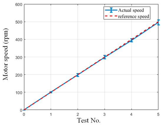
Figure 15.
Motor speed test.
From Figure 15, the optimized motor running speed is basically the same as the speed set value. That proves the correctness of the basic running principle of this motor. The driver has no speed feedforward control. It uses only a PID controller to control the motor speed. That causes the actual speed to be slightly lower than the speed set value in the whole speed range.
In the torque test, the magnetic powder clutch is replaced with a magnetic powder brake. By adjusting the input current of the brake, the brake can provide different loading torque in the process of the experiment. The motor sets the reference speed at 30 rpm. Then, it adjusts the input current of the brake to change the loading torque, and its value feedback from the torque sensor. The loading torque values set ranges from 0 to 5 Nm with a step of 1 Nm. In each situation, the motor runs at a constant torque, and the three-phase current is measured and averaged at its RMS value to represent the input current. The torque and current are tested and the results are shown in Figure 16.
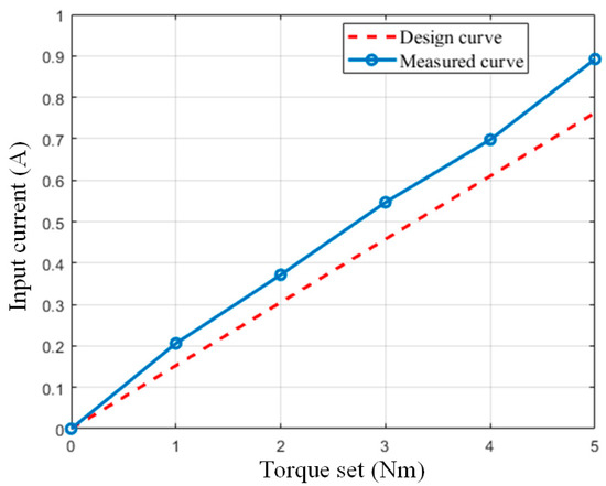
Figure 16.
Input current and output torque.
From Figure 15, the ratio of current to torque is almost linear, and it is close to the data solved from FEM. In general, the experimental measurement of the motor is basically verified by some basic indicators of the motor design performance. But compared with the FEM calculation, the actual motor needs more current to generate the same torque. That is mainly because the losses in the actual system are too many. The losses of magnetic circuits, electrical circuits, bearing frictions, and machining errors have not been quantified. The FEM model is only an ideal situation.
6.2. Torque Ripple Test
In this test, the position of the magnetic powder clutch is replaced by a servo motor so that the speed/torque sensor is installed between the FSPM motor and the servo motor. When the test starts, the servo motor goes one round at the speed of 1 rpm. In this procedure, the sensor records the torque and the motor’s resolver records the rotor position at the same time. Then, the servo motor changes direction and goes one round again. This procedure repeats three times and the results are averaged. With the rotor position of the motor as the horizontal coordinate and the value of the torque sensor as the vertical coordinate, the torque ripple of the motor is shown in Figure 17.
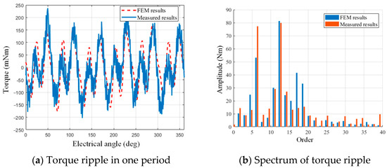
Figure 17.
Motor torque ripple.
Generally, from Figure 17, the torque ripple basically matches the performance calculated by FEM. At the sixth-order frequency, the experimental measurements are slightly lower than those calculated by FEM. This may be due to the fact that the actual size of the motor is slightly different from the FEM, such as the small chamfer. Such small structures have the potential to smooth magnetic flux changes and thus reduce the amplitude of the torque ripple. The measured signal contains a large number of high-frequency signals, which is mainly due to the noise of the sensor. There is also some resistance to torque during actual rotation. This is mainly due to the existence of certain friction in parts such as bearings that support the motor rotor. Although no greased bearings were used on this prototype, the effects of friction resistance were still unavoidable.
7. Conclusions
The geometric sizes of the double salient pole of the FSPM motor have obviously influenced the average torque, torque ripple, and volume of the permanent magnet. Specifically, the stator salient pole angle brt, permanent magnet angle bpm, rotor salient pole angle bst, rotor salient pole top arc height Hrt, and rotor salient pole side angle Art are analyzed to create the function to torque characteristics. After optimization, the average torque has a 66.2% promotion, the absolute torque ripple reduces 91.4% of the original level, and the volume of the permanent magnet reduces 26.7% of the original level. Finally, the prototype was made and the experiment proved that the method to improve the motor torque is feasible and efficient.
Author Contributions
Conceptualization, C.L. and D.X.; methodology, C.L.; software, B.Y.; validation, D.X. and W.W.; formal analysis, B.Y.; investigation, D.X.; writing—original draft preparation, C.L.; funding acquisition, C.L. All authors have read and agreed to the published version of the manuscript.
Funding
This research was funded by the National Natural Science Foundation of China, grant number 52105532; and the Natural Science Basic Research Program of Shaanxi, grant number 2024JC-YBMS-344.
Data Availability Statement
The raw data supporting the conclusions of this article will be made available by the authors on request.
Conflicts of Interest
The authors declare no conflict of interest.
References
- Denkena, B.; Ahlborn, P. Linear-rotary direct drive for multi-functional machine tools. Cirp. Ann. Manuf. Technol. 2022, 71, 349–352. [Google Scholar] [CrossRef]
- Yang, X.; Li, J.; Xuan, J.; Zhao, W. Influence of the Machining Process on the Thrust Force and Mechanical Characteristics for the Direct Drive System. Processes 2023, 11, 17. [Google Scholar] [CrossRef]
- Park, J.; An, J.; Han, K.; Choi, H.-S.; Park, I.S. Enhancement of cooling performance in traction motor of electric vehicle using direct slot cooling method. Appl. Therm. Eng. 2022, 217, 15. [Google Scholar] [CrossRef]
- Wang, P.; Hua, W.; Wang, G.; Zhang, Z.; Hu, M. Comparative Study of Flux-Switching Permanent Magnet Machine with C- and E-Shaped Cores Based on Magnetic Field Modulation Theory. IEEJ Trans. Electr. Electron. Eng. 2023, 18, 270–277. [Google Scholar] [CrossRef]
- Zhu, J.; Wu, L.; Wen, H. Optimization and Comparison of Dual-Armature Flux-Switching Permanent Magnet Machines with Different Stator Core Shapes. IEEE Trans. Ind. Appl. 2022, 58, 314–324. [Google Scholar] [CrossRef]
- Zhu, Z.Q.; Chen, J.T. Advanced Flux-Switching Permanent Magnet Brushless Machines. IEEE Trans. Magn. 2010, 46, 1447–1453. [Google Scholar] [CrossRef]
- Zhou, J.; Xiao, X. Combined methods for torque variation reduction of high-speed FSPM. Energy Rep. 2023, 9, 199–206. [Google Scholar] [CrossRef]
- Jiang, M.; Zhu, X.; Xiang, Z.; Quan, L.; Que, H.; Yu, B. Suppression of Torque Ripple of a Flux-Switching Permanent Magnet Motor in Perspective of Flux-Modulation Principle. IEEE Trans. Transp. Electrif. 2022, 8, 1116–1127. [Google Scholar] [CrossRef]
- Soomro, I.A.; Sulaiman, E.B.; Ahmad, M.Z.B.; Azis, R. Performance Analysis and Comparison for Various Excitation Source Salient Rotor with Modular Rotor Permanent Magnet of Flux Switching Machine. J. Electr. Eng. Technol. 2023, 18, 2771–2782. [Google Scholar] [CrossRef]
- Yan, J.; Lin, H.; Feng, Y.; Zhu, Z.Q.; Jin, P.; Guo, Y. Cogging Torque Optimization of Flux-Switching Transverse Flux Permanent Magnet Machine. IEEE Trans. Magn. 2013, 49, 2169–2172. [Google Scholar] [CrossRef]
- Farahani, E.F.; Baker, N.J.; Mahmouditabar, F. An Innovative H-Type Flux Switching Permanent Magnet Linear Generator for Thrust Force Enhancement. Energies 2023, 16, 5976. [Google Scholar] [CrossRef]
- Zhang, Z.; Wang, H.; Chen, H. A new design approach for reduction of force ripple in permanent magnet flux-switching linear motor. IET Electr. Power Appl. 2023, 17, 1148–1158. [Google Scholar] [CrossRef]
- Ullah, W.; Khan, F.; Sulaiman, E.; Umair, M.; Ullah, N.; Khan, B. Analytical validation of novel consequent pole E-core stator permanent magnet flux switching machine. IET Electr. Power Appl. 2020, 14, 789–796. [Google Scholar] [CrossRef]
- Chen, Z.X.; Cui, Y.J. Numerical Simulation and Experimental Validation of a Flux Switching Permanent Magnet Memory Machine. IEEE Access 2020, 8, 194904–194911. [Google Scholar] [CrossRef]
- Torn, V.; Seangwong, P.; Fernando, N.; Siritaratiwat, A.; Khunkitti, P. Performance Improvement of Flux Switching Permanent Magnet Wind Generator Using Magnetic Flux Barrier Design. Sustainability 2023, 15, 8867. [Google Scholar] [CrossRef]
- Petkar, S.G.; Thippiripati, V.K. A Novel Duty-Controlled DTC of a Surface PMSM Drive with Reduced Torque and Flux Ripples. IEEE Trans. Ind. Electron. 2023, 70, 3373–3383. [Google Scholar] [CrossRef]
- Hua, W.; Cheng, M.; Zhu, Z.Q.; Howe, D. Analysis and optimization of back-EMF waveform of a novel flux-switching permanent magnet motor. In Proceedings of the 2007 IEEE International Electric Machines & Drives Conference, Antalya, Turkey, 3–5 May 2007; pp. 1025–1030. [Google Scholar]
- Zhu, D.; Shen, C.; Du, Y.; Xiao, F. Pole-Shape Optimization of Flux-Switching Permanent Magnet Machine; Institute of Electrical and Electronics Engineers Inc.: Hangzhou, China, 2014; pp. 1681–1684. [Google Scholar]
- Zhu, X.; Hua, W. Back-EMF Waveform Optimization of Flux-Switching Permanent Magnet Machines; Institute of Electrical and Electronics Engineers Inc.: Lausanne, Switzerland, 2016; pp. 2419–2425. [Google Scholar]
- Ma, Z.; Cheng, M.; Zhao, C. Analytical Investigation and Topology Evolution of Rotor Salient Pole Reluctance in the Flux-Switching Permanent Magnet Machine; Institute of Electrical and Electronics Engineers Inc.: Zhuhai, China, 2023; pp. 130–135. [Google Scholar]
- Ullah, W.; Khan, F.; Umair, M. Multi-Objective Optimization of High Torque Density Segmented PM Consequent Pole Flux Switching Machine with Flux Bridge. CES Trans. Electr. Mach. Syst. 2021, 5, 30–40. [Google Scholar] [CrossRef]
Disclaimer/Publisher’s Note: The statements, opinions and data contained in all publications are solely those of the individual author(s) and contributor(s) and not of MDPI and/or the editor(s). MDPI and/or the editor(s) disclaim responsibility for any injury to people or property resulting from any ideas, methods, instructions or products referred to in the content. |
© 2024 by the authors. Licensee MDPI, Basel, Switzerland. This article is an open access article distributed under the terms and conditions of the Creative Commons Attribution (CC BY) license (https://creativecommons.org/licenses/by/4.0/).