Abstract
Inchworms are a widely adopted bio-inspired model for soft crawling robots. Taking advantage of the good controllability of Shape Memory Alloy (SMA), this paper designs and manufactures an inchworm-inspired soft robot driven by SMA. Firstly, in the structural design, the paper compares the heat dissipation performance and driving efficiency of SMA actuators with two assembly forms: embedded and external to the silicone body. The external structure assembly design with superior performance is chosen. Secondly, in the analysis of the motion characteristics of the soft robot, a kinematic model is developed. Addressing the issue of inaccurate representation in traditional constitutive models due to difficult-to-measure parameters, such as martensite volume fraction, this paper derives an exclusive new constitutive model starting from traditional models using methods like the Taylor series and thermodynamic laws. The kinematic model is simulated using the Simulink platform to obtain its open-loop step response and sinusoidal signal response. Finally, an experimental platform is set up to conduct crawling tests on the soft robot in different planes. The experimental results show that the inchworm-inspired soft robot can perform continuous crawling motion, with a crawling speed of 0.041 mm/s on sandpaper under a constant current of 4A.
1. Introduction
Soft robots, as a research focus in the field of robotics, offer advantages over rigid robots, including high flexibility, excellent adaptability to the environment, and theoretically infinite degrees of freedom [1,2,3]. They have significant advantages in human–robot interaction, biomimicry, and operations in confined spaces, driving major breakthroughs in materials and design for biomimetic robots [4,5,6]. The inchworm, as a typical organism that crawls in a point-movement manner, with its unique and simple “Ω”-shaped movement, is a suitable model for the study of biomimetic soft crawling robots [7,8].
Currently, there is a diverse range of inchworm-inspired robots both domestically and internationally. The design approaches generally fall into two categories: simulating the adhesive function of the inchworm’s foot muscles [9] and simulating the coiling of the inchworm’s body in the middle driving section [10]. As shown in [11], the design of the foot section of the inchworm-inspired soft robot can be categorized into adhesive type and friction-changing type based on the contact relationship between its foot and the crawling surface during motion. Adhesive design refers to the use of adhesive devices in the foot structure, alternately controlling the adhesion of the front and rear feet to the ground, allowing the soft robot to crawl. A static electricity adhesive soft robot has been developed in [12], where the foot uses a static electricity adhesive device to control the release of static electricity to adjust the adhesion between the soft robot’s foot and the ground. In [13], the robot’s foot design uses a gripping device, with the legs adopting a nylon buckle structure to grip specific surfaces for crawling. However, compared to static electricity adhesion, it is challenging for a gripping device to change the adhesion level of the foot. Friction-changing design uses the friction force between the inchworm’s two feet and the ground to achieve crawling by generating friction differences between the front and rear feet during robot motion. In [14], an inchworm-inspired soft robot has been developed with a foot design where the front and rear feet use materials with different friction coefficients, causing different friction forces between the front and rear feet during crawling. The adhesive and friction-changing designs each have their advantages and disadvantages. An adhesive design often has better performance, but is more complex in design, requiring additional driving controls for foot adhesion. A friction-changing design mainly achieves crawling by changing the dynamic friction force between the front and rear feet, without the need for additional driving. Considering the small size of the designed soft robot, this study chooses a friction-changing foot design, using conical soft hairs on the sole to change the friction coefficient between the front and rear feet, thus creating a friction difference to drive the soft robot’s crawling.
The torso of the inchworm-inspired soft robot needs to be designed with a driver to mimic the inchworm’s body coiling. Currently, there are three main driving methods for the middle section of inchworm-inspired soft robots: gas-driven, cable-driven, and smart material-driven. In [15], an inchworm-inspired soft robot is gas-driven, inflating the gas chamber with gas. The differential extensibility of the soft material causes coiling as the central driving mechanism. The robot designed in [16] uses a cable-driven control to coil the body of the inchworm robot. In [17], an inchworm-inspired soft robot is designed based on the smart material Ionic Electroactive Polymer (IEAP) for driving. As shown in reference [18], a soft robot modeled after a leech and driven by SMA actuators has been developed. This robot crawls by electrifying the SMA material to contract it. Considering that the designed inchworm-inspired soft robot is small in size and does not require significant driving force, gas-driven systems often require large external devices, cable-driven systems need more external conditions, and many smart materials require multiple driving conditions. Smart material SMA has a small volume, low cost, and simple driving mechanism, making it well-suited to meet the driving requirements. Therefore, this study chooses smart material SMA as the driving element for the torso to simulate the inchworm’s body coiling.
The modelling of the inchworm-inspired soft robot mainly involves two parts: the kinematic modelling of the soft robot and the modelling of the shape memory process of the smart material SMA. Kinematic modelling primarily analyzes the forces and motion displacement of the soft robot [19]. As shown in [20], the kinematic modelling of the soft robot simplifies the feet into two points and the body into a curved beam to analyze the forces and motion states of the feet. For the modelling of the smart material SMA, it mainly describes the process of its shape memory due to electrical heating. A significant amount of research has been conducted on its modeling, especially the establishment of SMA constitutive models. As described in [21], the modelling process of SMA can be broadly divided into establishing thermodynamic models, phase transition dynamic models, and constitutive models. Various traditional SMA models were compared in reference [22], such as the Tanaka constitutive model and the Liang and Brinson series constitutive models. Analyzing these traditional constitutive models, it is not difficult to find that traditional models have parameters that are difficult to measure, such as the volume fraction of martensite, which affects the control of soft robots. Additionally, SMA materials from different manufacturers may vary, making traditional constitutive models not accurately applicable to all SMA materials. Modeling-related knowledge of dielectric elastomers is introduced in reference [23], where a new model for dielectric elastomers is established using mathematical methods, addressing challenges in controlling due to difficulties in characterizing certain parameters. Various mathematical methods for modeling soft robots are discussed in reference [24]. In this study, combining the above literature, we analyzed traditional models of SMA actuators and, addressing the difficulty of representation in traditional constitutive models, re-established the constitutive model of SMA actuators using mathematical methods. In conjunction with the model of the SMA actuator, we established the kinematic model of the soft robot.
Building upon prior research, this paper analyzes the kinematic mechanism of the inchworm, employing a smart material SMA as the actuator in the soft robot’s core and for the foot with a variable friction design. To assess the motion characteristics of the inchworm-inspired soft robot, a multi-field coupled kinematic model incorporating electrical, thermal, and force elements is constructed. Addressing the challenge of the difficult measurement of martensite volume fraction, which complicates the representation of traditional constitutive models, a specialized constitutive model for SMA materials is derived. Crawling motion experiments are designed to reveal general principles governing the locomotion of the soft inchworm robot. The insights gained hold significance for the future design and motion analysis of bio-inspired crawling robots.
2. Operational Principles and Structural Design of a Robot Mimicking the Motion of an Inchworm
2.1. Analysis of the Working Principles of the Inchworm
Inchworms are characteristic soft-bodied crawling animals in nature, displaying a distinctive creeping motion.
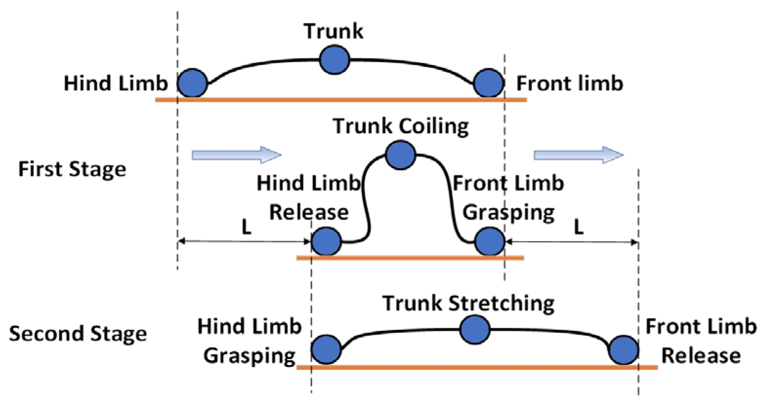
As shown in Figure 1, the crawling movement of the inchworm can be divided into two stages. In the first stage, the inchworm grips its front legs onto fixed objects like branches, with the rear legs in a released state. Then, the body curls into an “Ω” shape, moving the rear legs forward by a distance L. In the second stage, the inchworm’s rear legs grip onto the fixed object, and the front legs transition from a gripping to a released state. The body relaxes and extends, moving the front legs by a distance L. This repetitive cycle enables the inchworm to continuously crawl forward until it reaches its destination. Thus, the design focus of a biomimetic inchworm-inspired soft robot lies in achieving the periodic “Ω” shape bending motion of the robot’s body and having a “foot” structure with a variable friction coefficient on the contact surface.
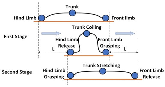
Figure 1.
Schematic representation of the motion pattern of the inchworm.
The inchworm’s “Ω” shape bending motion is due to the force exerted by the trunk muscles, causing the flexible body to contract. This paper uses soft silicone material to simulate the inchworm’s flexible body. It employs a designed SMA actuator to mimic the inchworm’s muscles, enabling the silicone body to perform the “Ω” shape bending motion. As for the foot structure of the inchworm, this paper observes the presence of conical soft hairs on its feet. After conducting a force analysis on the inchworm’s feet, the silicone body’s feet in this study also undergo a design featuring conical hairs. This design allows the soft robot, when driven, to generate different friction forces between the front and rear legs, thereby creating frictional disparity to propel the soft robot for crawling.
2.2. Selection and Assembly form Design of the Soft Robot’s Actuator
SMA material has a lower cost and is easy to drive, making it more suitable for the driving needs of the inchworm-inspired soft-bodied robot. Therefore, the soft robot uses a unidirectional SMA spring with a diameter of 6 mm and a wire diameter of 1.0 mm to drive the continuous “Ω” shape contraction and extension of the soft robot’s trunk.
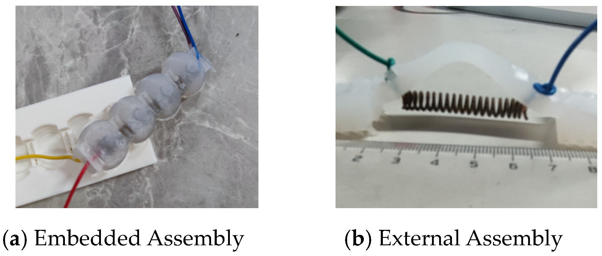
As shown in Figure 2a, there are various assembly methods for SMA actuators and the silicone body, with the most common being placing SMA springs inside the soft robot. This utilizes the SMA springs and connecting plates to drive the contraction and extension of the silicone body. Experimental measurements indicate that, firstly, it is difficult to calculate the optimal placement position for the partition. Secondly, due to the silicone wrapping, SMA’s heat dissipation is poor, leading to lower driving efficiency.
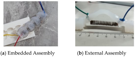
Figure 2.
Assembly form and testing experiments of the soft robot.
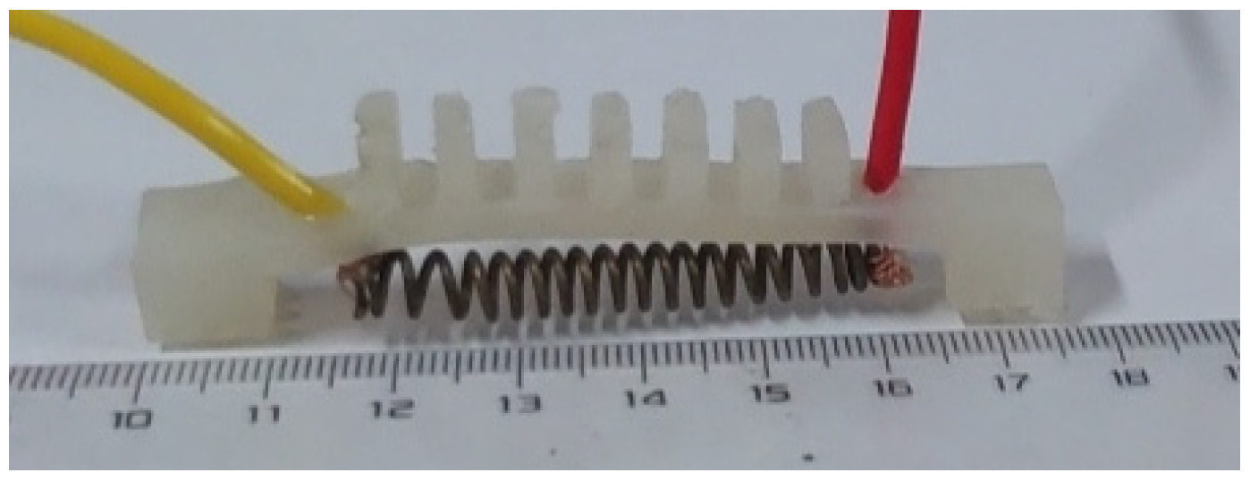
Thus, the soft robot has improved the placement of the SMA actuator by relocating the SMA spring from being entirely embedded inside the soft robot to being positioned at the lower end of the body. As shown in Figure 2b, the SMA spring is secured at the lower end of the soft robot using the designed connector and wires. In the powered state, the absence of a partition and the unidirectional nature of the SMA spring result in faster contraction. Following power shutdown, the SMA spring, free from silicone wrapping, dissipates heat more rapidly, resulting in a faster extension of the soft body under the pulling force of the spring’s recovery. According to experimental measurements, the drive time for one cycle with internal SMA is 7 min, whereas with external SMA material, it is 3 min. It is evident that the heat dissipation and operational efficiency of the SMA actuator are better when the SMA material is external.
2.3. Overall Structural Design of the Soft Robot
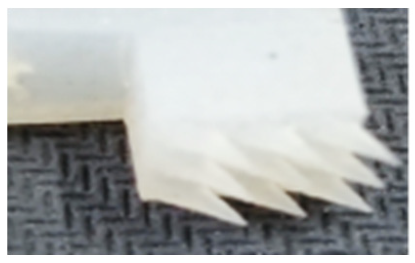
The inchworm-inspired soft-bodied robot is a combination of a silicone body and an SMA actuator. The silicone body uses 10-degree silicone, and the SMA actuator is affixed to the silicone body using wires and specialized silicone glue. Experimental findings indicate that the SMA spring has a length of 50 mm, contracting to 30 mm when fully heated. Considering the dimensions of the SMA actuator, the length of the soft robot’s body is configured as 60 mm, with a width of 10 mm and thickness of 5 mm. Rectangular blocks, measuring 10 mm in length, 3 mm in width, and 6 mm in height, are strategically designed on the body to reduce stiffness during bending. The “feet” are designed to provide sufficient weight for overall stability, with dimensions of 10 mm in length, width, and height. To facilitate the continuous crawling motion of the soft robot, it is essential to ensure that the front and rear “feet” generate distinct frictional forces with the ground when the SMA actuators are in operation. As a result, conical bristles are incorporated on the ground-contacting surface of the “feet”. As shown in Figure 3, due to the addition of the conical foot structure, there is a friction difference between the front and rear feet during motion, thereby propelling the soft robot to achieve continuous crawling. As shown in Figure 4, the complete structure of the soft robot is composed of a silicone body, SMA actuators, and connecting elements.

Figure 3.
Conical spikes.

Figure 4.
Structure of soft robots.
3. Modeling of Electrical–Thermal–Mechanical Multi-Field Coupling in Soft Robots
The modelling of the caterpillar-inspired soft robot encompasses the constitutive equations of SMA, phase transition dynamics equations, thermodynamic equations, and the kinematic equations of the robot.
3.1. Thermodynamic Equation
Electrically heating the SMA spring that drives the robot’s motion, a portion of the electrical energy transforms into the internal energy and latent heat of phase transition in the SMA spring, triggering a heating-induced phase transition. Another portion does work on the environment, dissipating away. Therefore, the thermodynamic equilibrium equation for the SMA spring is given by:
where is the mass of the SMA material, is the specific heat capacity of the SMA material, T is the temperature of the SMA material, is the ambient temperature, I is the heating current, is the duration of electrical heating, is the electrical resistance of the SMA material, is the electrical characteristic parameter of the SMA material, is the volume fraction of martensite in the SMA material, is the thermal conductivity parameter, and is the heat exchange area.
3.2. Material Constitutive Equation
In 1986, based on the differential forms of the first and second laws of thermodynamics, Tanaka established the constitutive model of SMA by incorporating knowledge of thermodynamics. In 1990, Liang et al. built upon Tanaka’s constitutive equation, replacing the Tanaka exponential phase transition equation with a cosine form and assuming constant elastic modulus, phase transition modulus, and thermoelastic modulus in the Tanaka constitutive equation. Building on the work of Tanaka and Liang, Brinson considered the influence of stress on the volume fraction of martensite, refining the shape memory model of SMA [22].
Tanaka’s incremental constitutive model is as follows:
where is the elastic modulus, is the phase transition modulus, and is the thermoelastic modulus.
As shown in Equation (1), Tanaka and colleagues’ model describes the shape memory effect of SMA springs using parameters like martensite volume fraction, temperature, and strain. Given the difficulty in measuring values such as the martensite volume fraction in laboratories, experiments typically focus on the relationship between strain, stress, and temperature. The Taylor series can replace traditional constitutive equations with a polynomial, aiding in the development of a new constitutive model. Building on previous SMA modeling efforts, this paper combines thermodynamic laws and the Taylor series to derive a constitutive equation that solely relates stress, strain, and temperature, capturing the constitutive behavior of SMA alloys.
Considering the practical requirement for a relationship only between stress, strain, and temperature, let us assume:
Expanding (1) at the initial state using bivariate Taylor series gives:
In the phase transition process, SMA adheres to the Clausius–Clapeyron equation, expressed as:
where is the latent heat of phase transition from austenite to martensite in the shape memory alloy, is the density of SMA, and is the latent potential of phase transition from austenite to martensite in the shape memory alloy.
From Equations (3) and (4), it is apparent that the rate of change of stress with respect to temperature is constant, and the higher-order derivatives of stress with respect to temperature are all zero. Consequently, we have:
Furthermore, since the initial conditions are zero and the values of higher-order terms are negligible, and given that the soft robot does not require a high degree of model accuracy, the higher-order terms can be ignored. Therefore, the constitutive model for SMA is given by:
where: and are undetermined parameters.
3.3. Tanaka’s Equation for Phase Transition Dynamics
The first proposed phase transition dynamics equation for martensite by Meger [22] is:
where is the average volume of the newly formed martensite, is a constant, and is the free energy driving force for martensite phase transition.
Assuming and are constants, integrating Equation (7) over temperature T from to T, and considering the zero-stress state of martensite during its phase transition, the volume fraction is expressed as:
where is a constant, and and are the temperatures at the end and the beginning of martensite phase transition, respectively.
Then, during the austenite phase transition:
where is a constant, and and are the temperatures marking the end and the start of martensite phase transition, respectively.
When considering the presence of stress, the phase transition temperatures of SMA will change, and the temperature ranges in the above equations need to be adjusted.
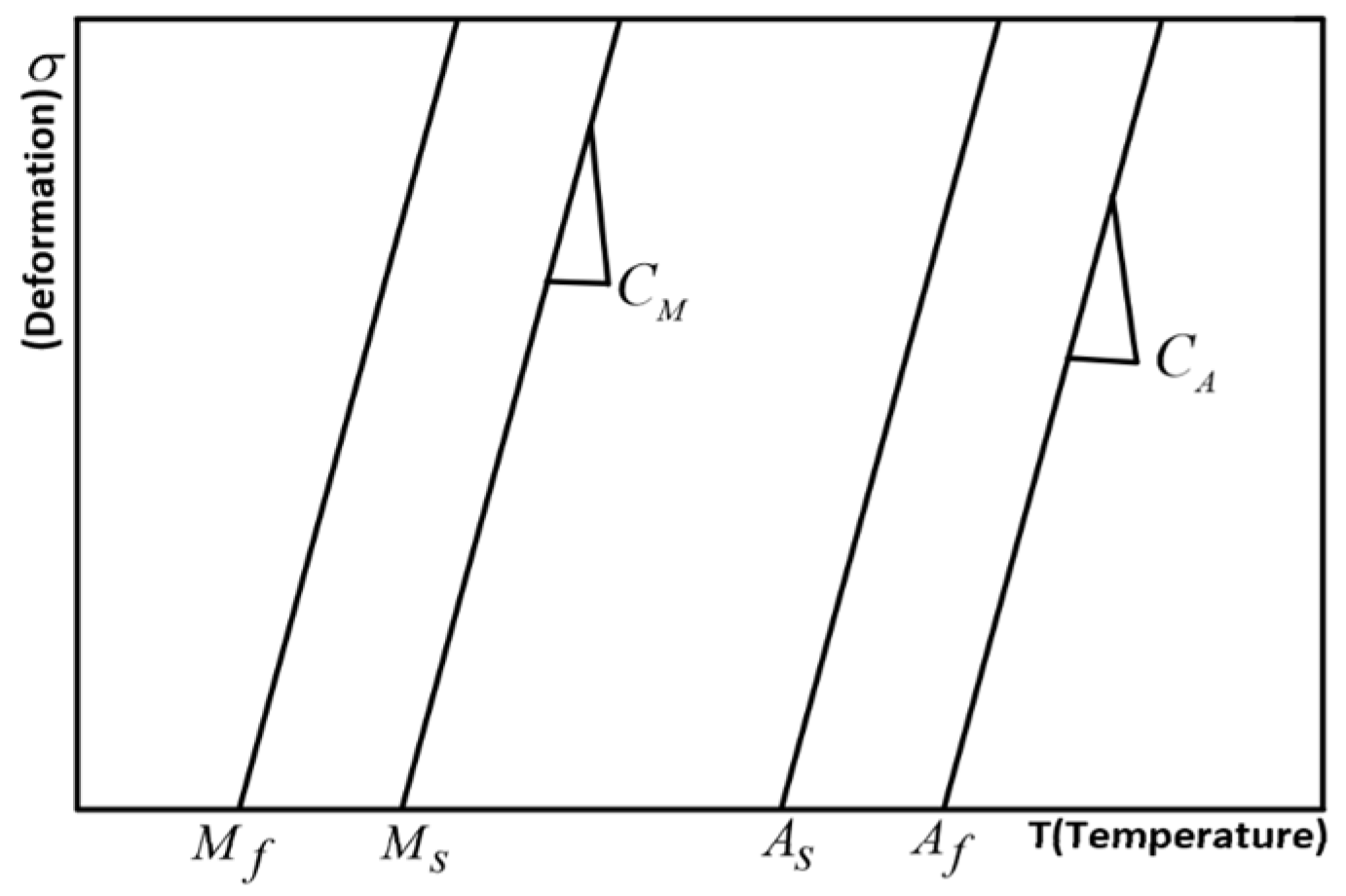
As shown in Figure 5, the phase transition temperature under stress exhibits a linear relationship with stress; therefore, it can be derived as:
where and are the influence coefficients for martensite and austenite, respectively. and represent the corrected starting temperature and finishing temperature of the martensitic transformation.
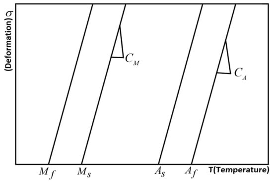
Figure 5.
Temperature–stress relationship curve.
Combining Equations (8)–(11), the process of martensite transforming into austenite is obtained as follows:
The process of austenite transitioning to martensite is as follows:
where and are constants representing the influence of temperature on the phase transition process, and and are also constants representing the influence of stress on the phase transition process.
Assuming martensite transformation is complete at and austenite transformation is complete at , the values of the integral constants , , , and can be determined as follows:
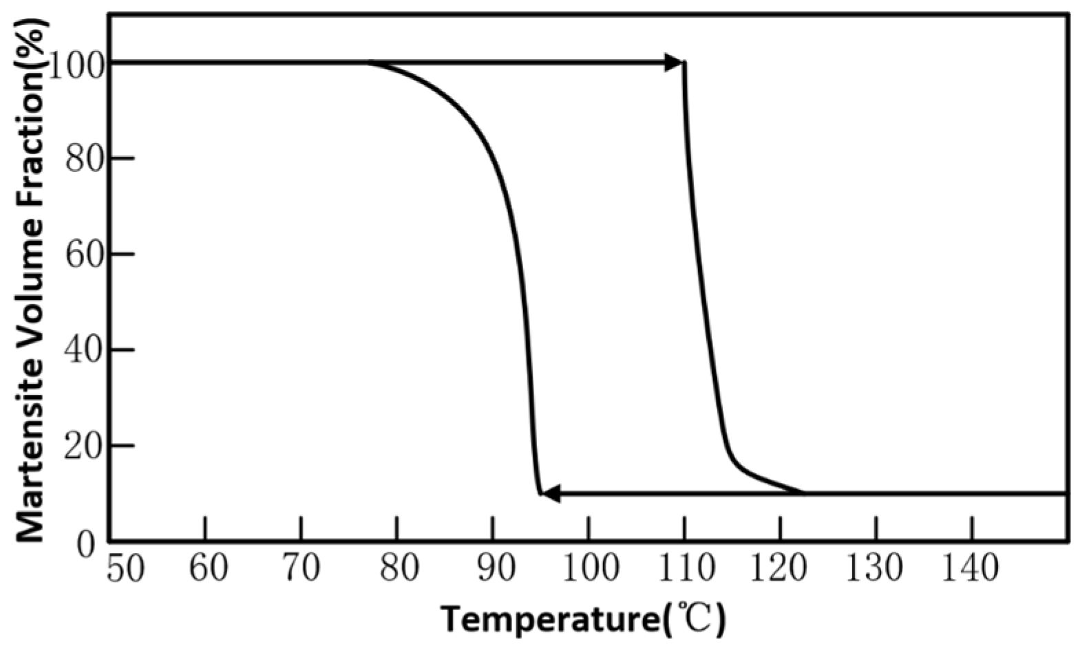
In conclusion, combining with Figure 6, the Tanaka phase transition dynamics equation is:

Figure 6.
Martensite–austenite volume fraction–temperature change curve under load.
3.4. Equations of Robot Kinematics
The caterpillar-inspired soft robot utilizes an electrical power source to induce Joule heating in SMA springs, causing contraction and generating bidirectional tension. This drives the “bipedal” motion of the soft robot, allowing simultaneous inward or outward movement. Additionally, the friction pattern design on the feet generates a frictional difference, thereby propelling the soft robot’s crawling motion.
To better express the crawling process of the soft robot, we make the following assumptions: (1) the strain in the silicone body of the soft robot is finite; (2) during crawling, the sliding friction force is equal to the pressure multiplied by the friction coefficient; (3) we disregard the impact of gravity on the silicone body of the soft robot and the inertial force generated by motion during crawling.
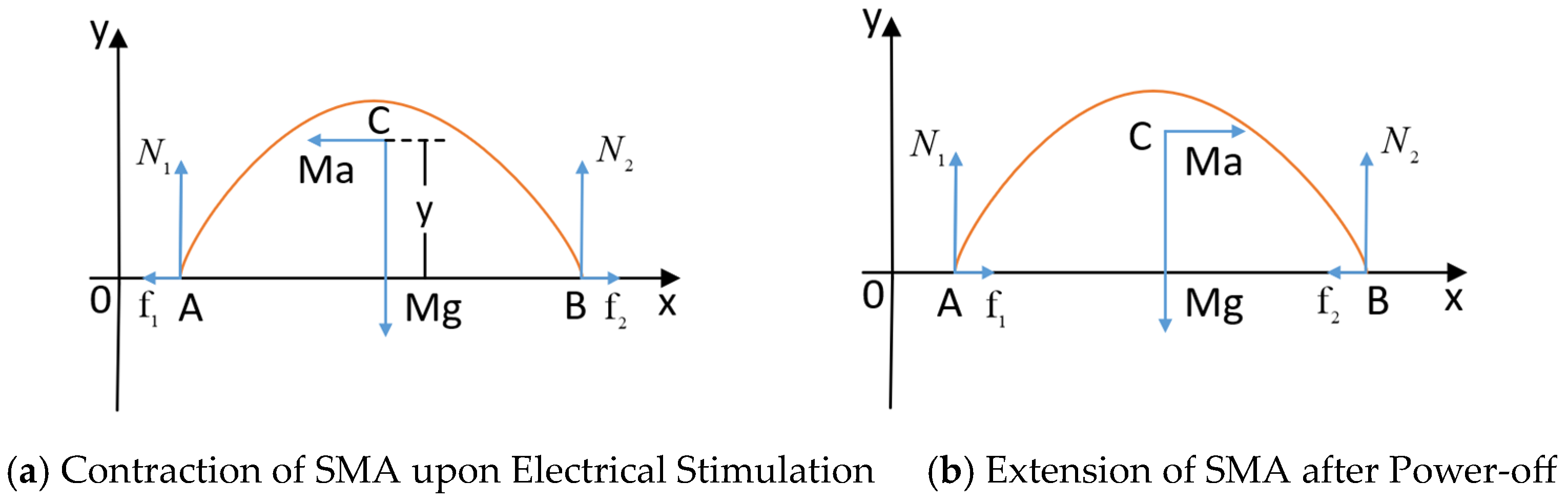
For a better kinematic analysis, the silicone body and SMA spring are considered as a whole, represented by a simplified circular arc with the center of mass at point C. The “bipedal” structure is simplified to two contact points, A and B. Force analysis is conducted for two stages of the soft robot’s crawling motion within one cycle. The force analysis during the crawling process of the soft robot is illustrated in Figure 7. A Cartesian coordinate system is established, with the crawling direction of the soft robot as the positive x-axis and the upward direction of the silicone body as the positive y-axis. Figure 7a depicts the force diagram when the SMA spring contracts due to heating, and Figure 7b shows the force diagram when the SMA extends during cooling. In this figure, f1 and f2 represent the frictional forces between the soft robot’s feet and the ground, N1 and N2 represent the ground support forces, Mg is gravity, and Ma is the net external force.
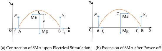
Figure 7.
Force analysis diagram for the crawling motion of the robot over one cycle.
Due to the conical bristle design on the underside of the feet, when the SMA actuators are powered, the friction coefficients between the front and rear feet of the soft robot are different. Considering the varying friction coefficients, the motion of the soft robot is divided into two stages: contraction and extension of the SMA material. In the second stage, the friction force at point A counteracts the driving force of the SMA spring, while point B continues to move forward under the influence of elastic force. To address this, a moment is introduced when point A is stationary, and point B moves to under the action of elastic force and inertia. Dynamic analyses are conducted for points A and B of the soft robot, where represents stress. The positive pressures at points A and B should be equal, i.e., , where t is time. The friction coefficients between points A and B and the ground are assumed to be and respectively.
At Point A:
Hence, the displacement at Point A is:
At Point B:
Hence, the displacement at Point B is:
We performed kinematic analysis for each of the three stages to obtain the motion states of A, B, and the foot. The results are summarized in Table 1.

Table 1.
Analysis table for crawling motion of soft robot.
4. Parameter Estimation and Model Validation Experiment for SMA Material Constitutive Model
4.1. Determination of Parameters for SMA Material Constitutive Model
In the previous text, the constitutive model of SMA material was obtained through the Taylor series, as given by Equation (7). To determine the undetermined parameters in the simplified constitutive model, as shown in Figure 8, the relationship between temperature, strain, and stress of SMA material is first experimentally determined. Subsequently, the Origin software’s curve fitting module is employed to process the data and solve for the undetermined coefficients in the simplified model.
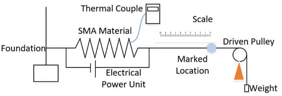
Figure 8.
Schematic diagram of experimental validation for the constitutive model.
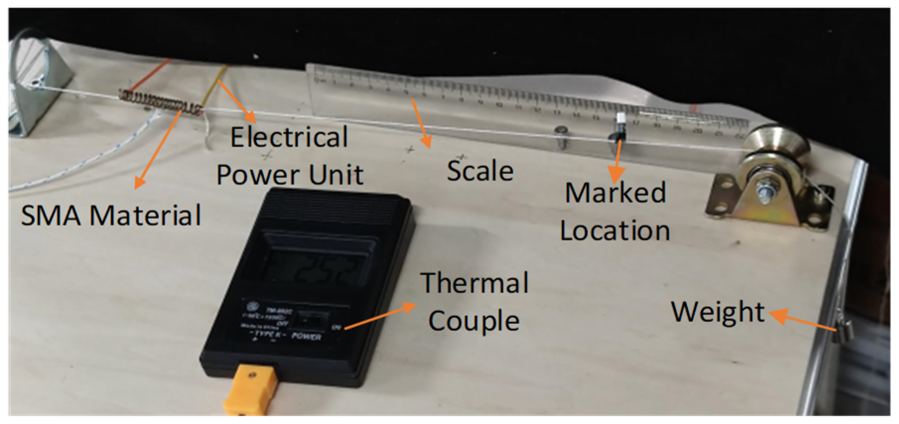
To measure the temperature of SMA material under electrical strain, a type TM902c thermocouple is employed. The SMA material is secured on a moving pulley using nylon thread, with the end of the nylon thread attached to a standard weight to represent the magnitude of external stress. A standard ruler is utilized to measure the displacement at the marked location, and a camera is used to record the displacement of the nylon thread marker, representing the strain of the SMA material. The detailed experimental platform is depicted in Figure 9.

Figure 9.
Experimental validation platform for the constitutive model.
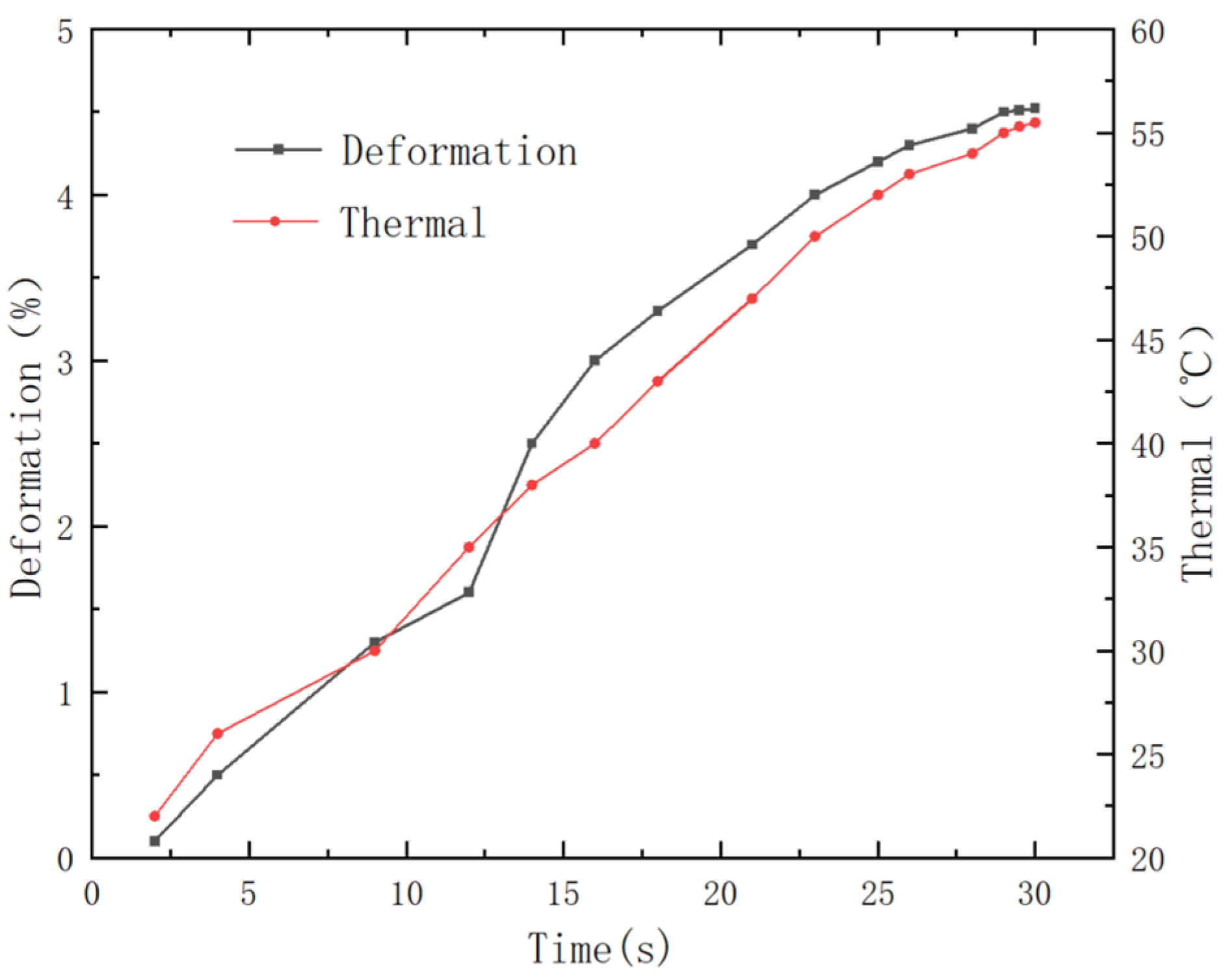
Attach a 10 g weight to the end of the nylon rope, apply electrical current to the SMA material, and collect heating temperature and strain data. Plot the temperature–strain–time curves under different currents and different SMA material conditions, as shown in Figure 10.
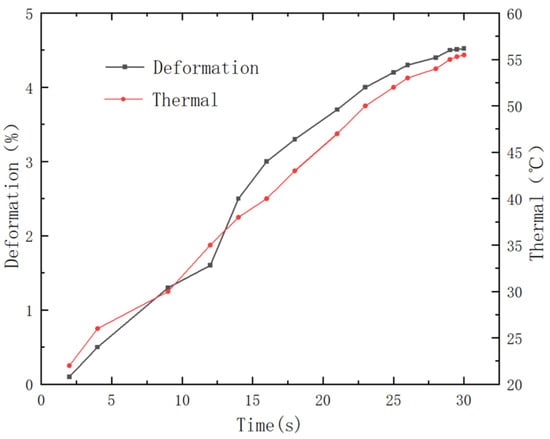
Figure 10.
Time–strain and time–temperature curves of SMA material under 10 g load.
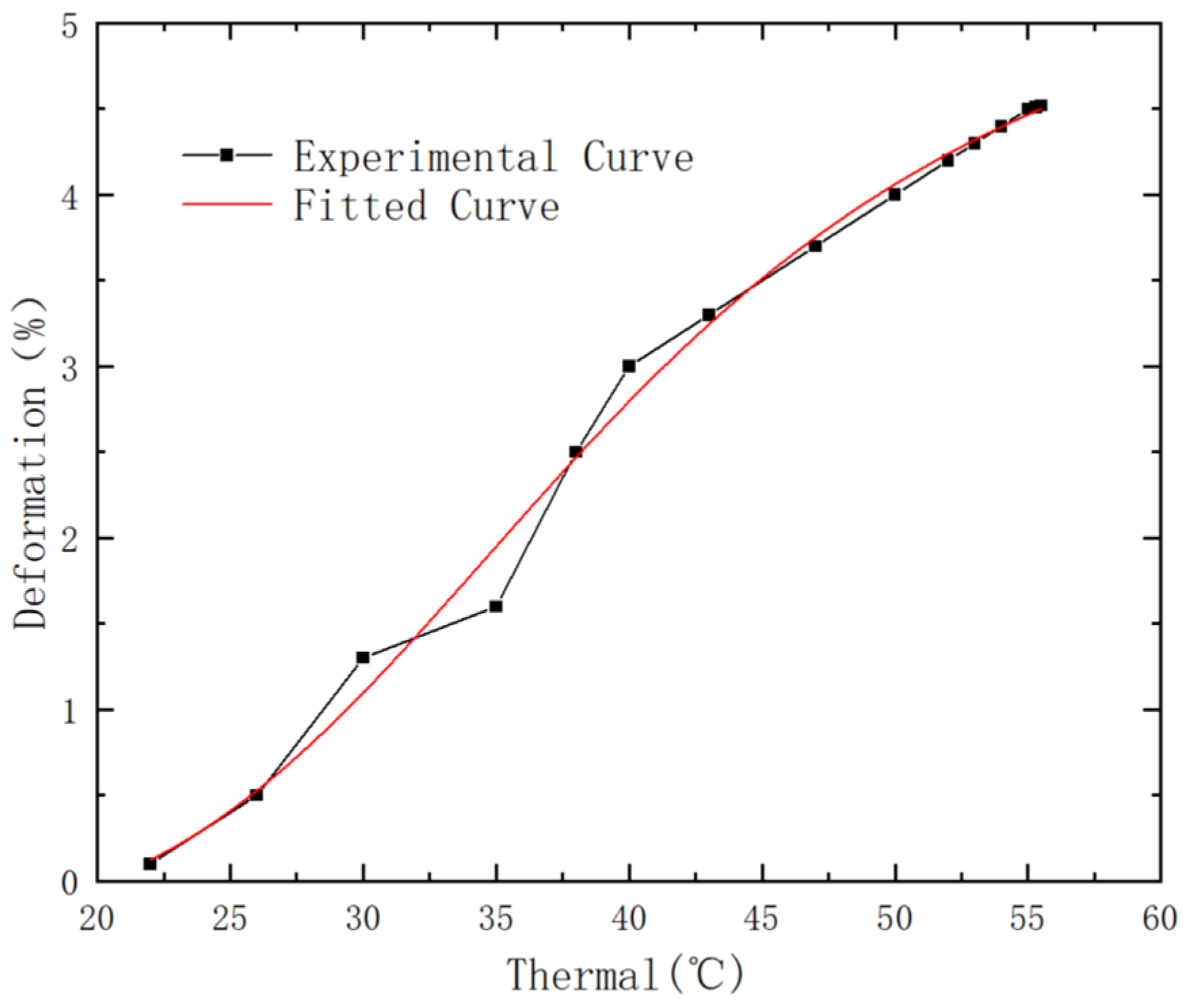
Substitute experimental data into the simplified constitutive equation, taking the example of a 6 mm diameter, 1.0 mm wire diameter, electrically heated and contracted SMA spring. Utilize Origin for curve fitting by inserting into the constitutive equation (Equation (7)). The resulting fitted curve is shown alongside the experimental curve in Figure 11.
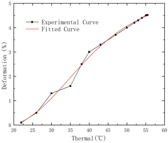
Figure 11.
Experimental and fitted curves of the constitutive model under 10 g load.
Subsequently, experiments are conducted on springs with diameters of 7 mm and wire diameters of 1 mm, subjected to electrical heating and contraction, as well as electrical heating and elongation. The experimental results are fitted, and the numerical values of the undetermined parameters for the SMA spring constitutive model are shown in Table 2.
Table 2.
Fitting parameter table for different SMA spring constitutive models.
4.2. Verification of SMA Material Constitutive Model
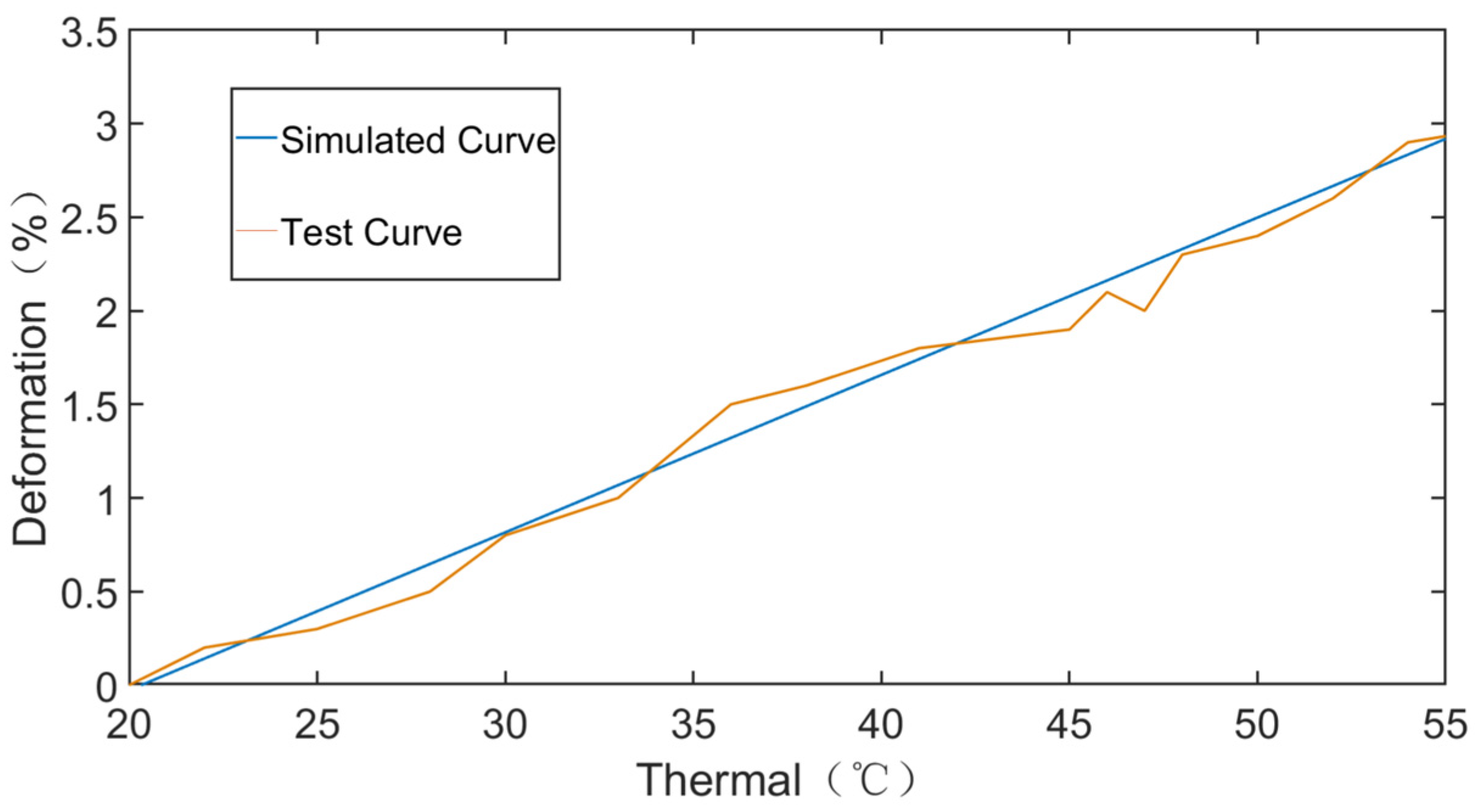
To validate the correctness of the above constitutive model, the weight is changed by replacing the 10 g weight with a 20 g weight. Subsequently, a constitutive model verification experiment is conducted on the loaded SMA spring with a diameter of 6 mm and a wire diameter of 1.0 mm. The experimental results and MATLAB simulation curve are shown in Figure 12. The results indicate that the simulated curve has a small deviation from the experimental curve, confirming the basic rationality of the derived constitutive model.
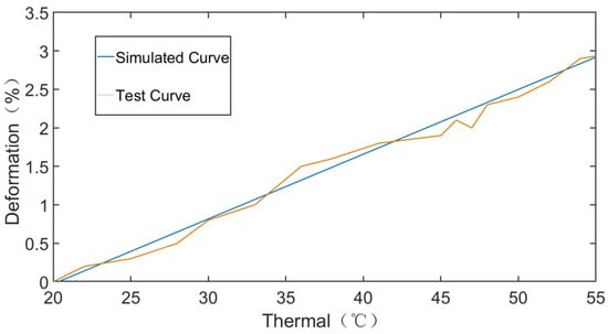
Figure 12.
Experimental and simulated curves of the constitutive model under 20 g load.
5. Kinematic Model Simulation and Crawling Motion Experiment of Inchworm-Inspired Soft Robot
5.1. Kinematic Simulation of Soft Robot on Simulink
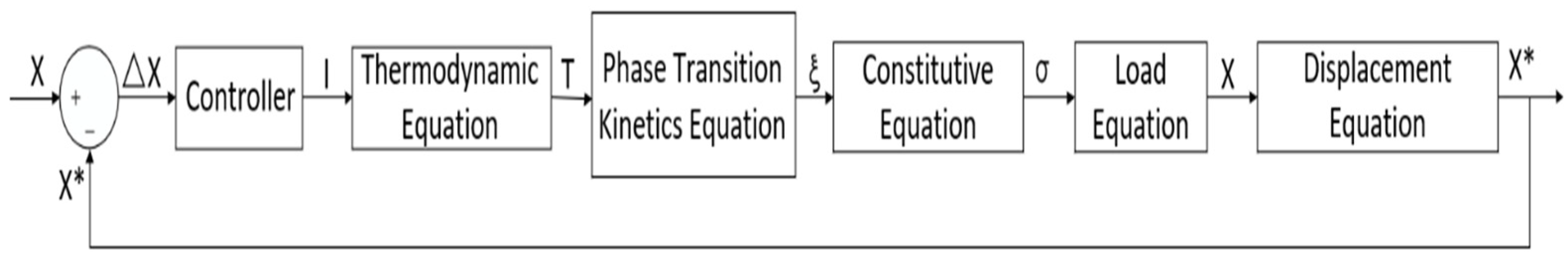
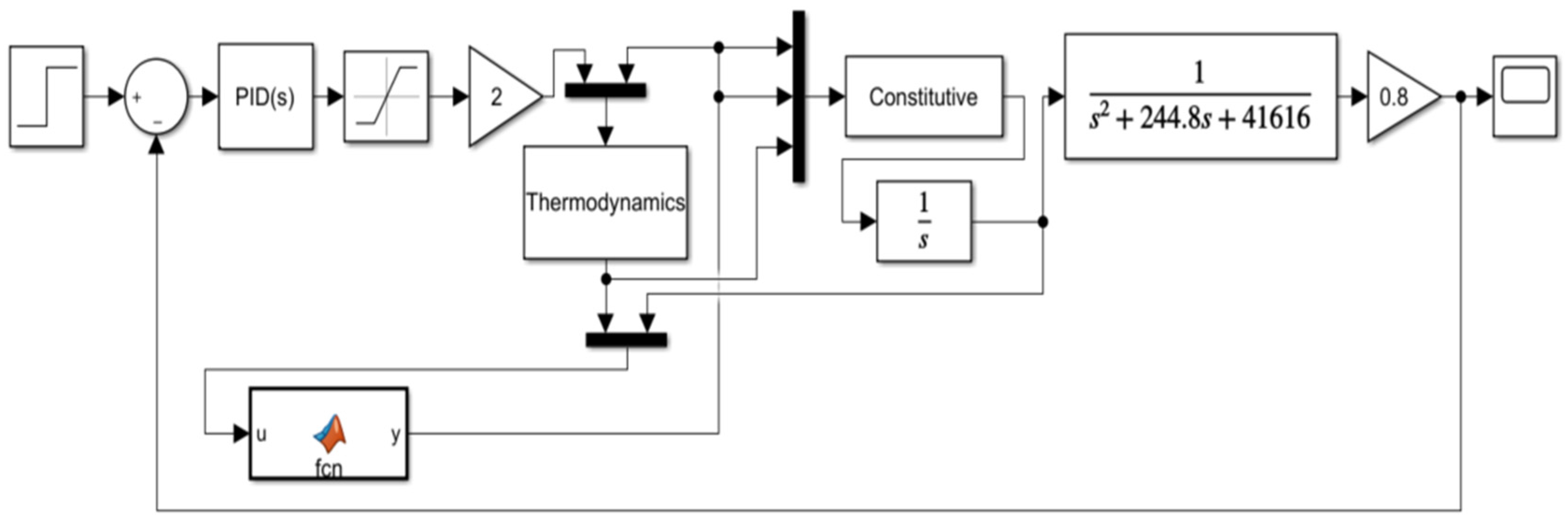
Utilizing the Simulink module in MATLAB software to kinematically model the crawling motion of soft robots, the control block diagram is shown in Figure 13. Place the various modules from the control block diagram on Simulink for kinematic model simulation. The model is shown in Figure 14. In this context, I represents current, T represents temperature, represents martensite volume fraction, represents strain, X represents SMA spring displacement, and X* indicates the displacement of the soft robot. The controller section of the model employs a PID control approach. Initially, both the I and D terms are set to zero, and the P parameter is assigned a modest value. The system’s response is then observed as the P parameter is incrementally increased until the system begins to diverge or oscillate. At this critical point, the P parameter’s threshold is identified, and Kp is set to 60% of this threshold. Subsequent adjustments are made to the I and D parameters based on the actual system’s dynamic response to determine the three parameters of the PID controller.
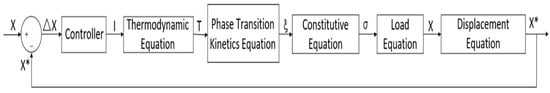
Figure 13.
Control block diagram for kinematic modeling of soft robot.
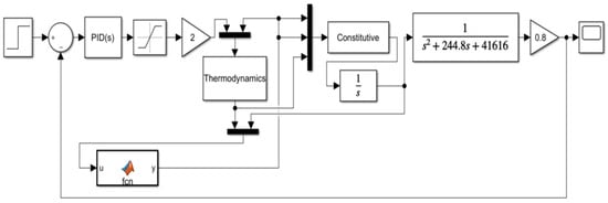
Figure 14.
Kinematic model of soft robot.
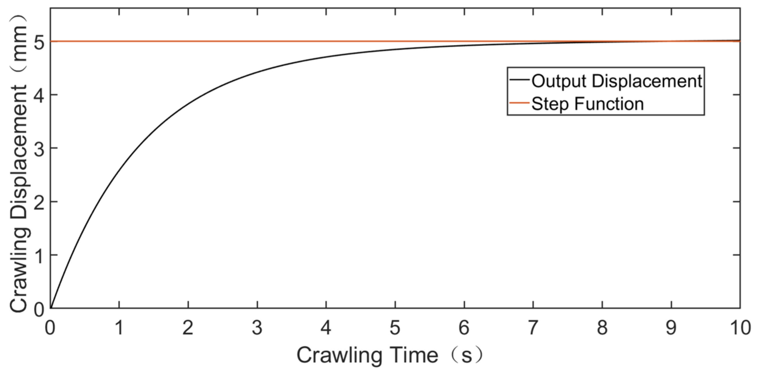
The kinematic model, with the displacement of the soft robot as the controlled variable, includes modules such as the controller, thermodynamic module, and phase transition dynamics module. It describes the relationship between displacement and time for an inchworm-inspired soft robot over one cycle. In practical experiments, it was observed that there is a temperature limit during the transformation between martensite and austenite phases, leading to thermal hysteresis in SMA materials. When the SMA actuator operates, there is a significant cooling time. Therefore, the model undergoes open-loop step response testing and sinusoidal signal testing, with simulation results taken during the operation of the SMA actuator in the cycle. Two-dimensional plots of the results are shown in Figure 15 and Figure 16.
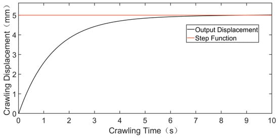
Figure 15.
Open-loop step signal response of the model.
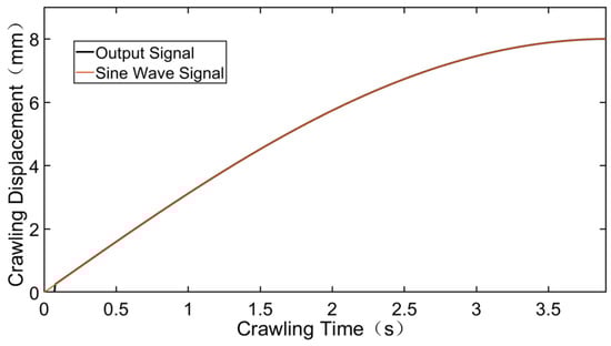
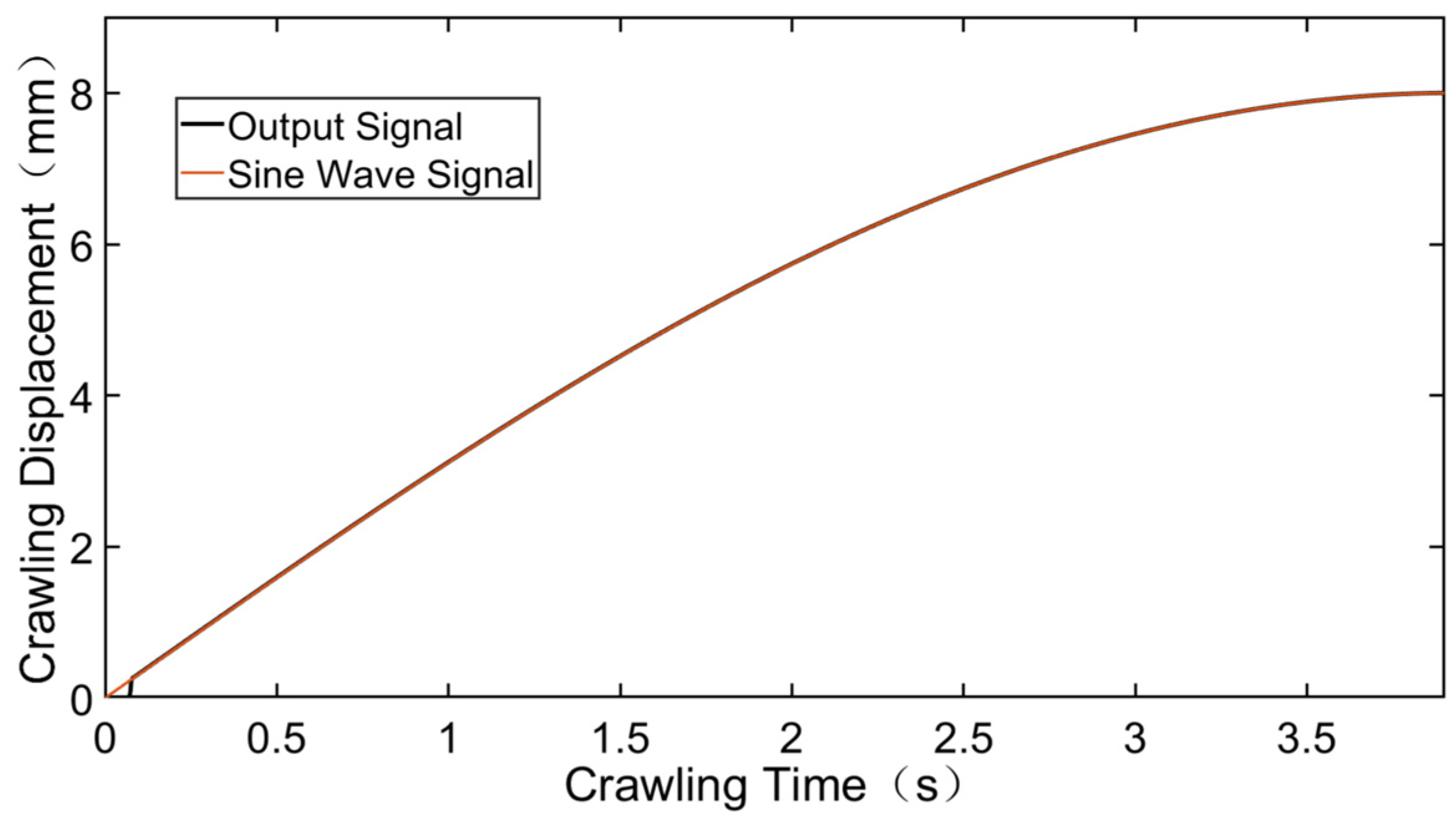
Figure 16.
Sinusoidal signal response of the model.
Based on the open-loop step response simulation results, with the SMA actuator in operation and a step input signal, the analysis of the soft robot crawling 5 mm reveals that the output displacement reaches stability after approximately 6.5 s of rise time. The overall system overshoot is relatively small. The simulation results validate the effectiveness of the model.
As the controlled output is crawling displacement, the soft robot can only move in one direction. Therefore, a sine signal, representing a quarter of a cycle, is used to test the controller’s effectiveness. During the shape memory process of SMA material, as shown in Figure 6, the transformation between martensite and austenite occurs under certain temperature conditions, leading to thermal hysteresis in SMA materials during driving. Analyzing the simulation results in Figure 16, due to the thermal hysteresis and inertia of SMA materials, there is an initial lag in the output displacement. During the crawling motion of the soft robot driven by SMA material, the sinusoidal signal response results show that when the temperature reaches the martensite phase transition condition, the output displacement essentially tracks the desired displacement.
5.2. Crawling Experiment of Soft Robot
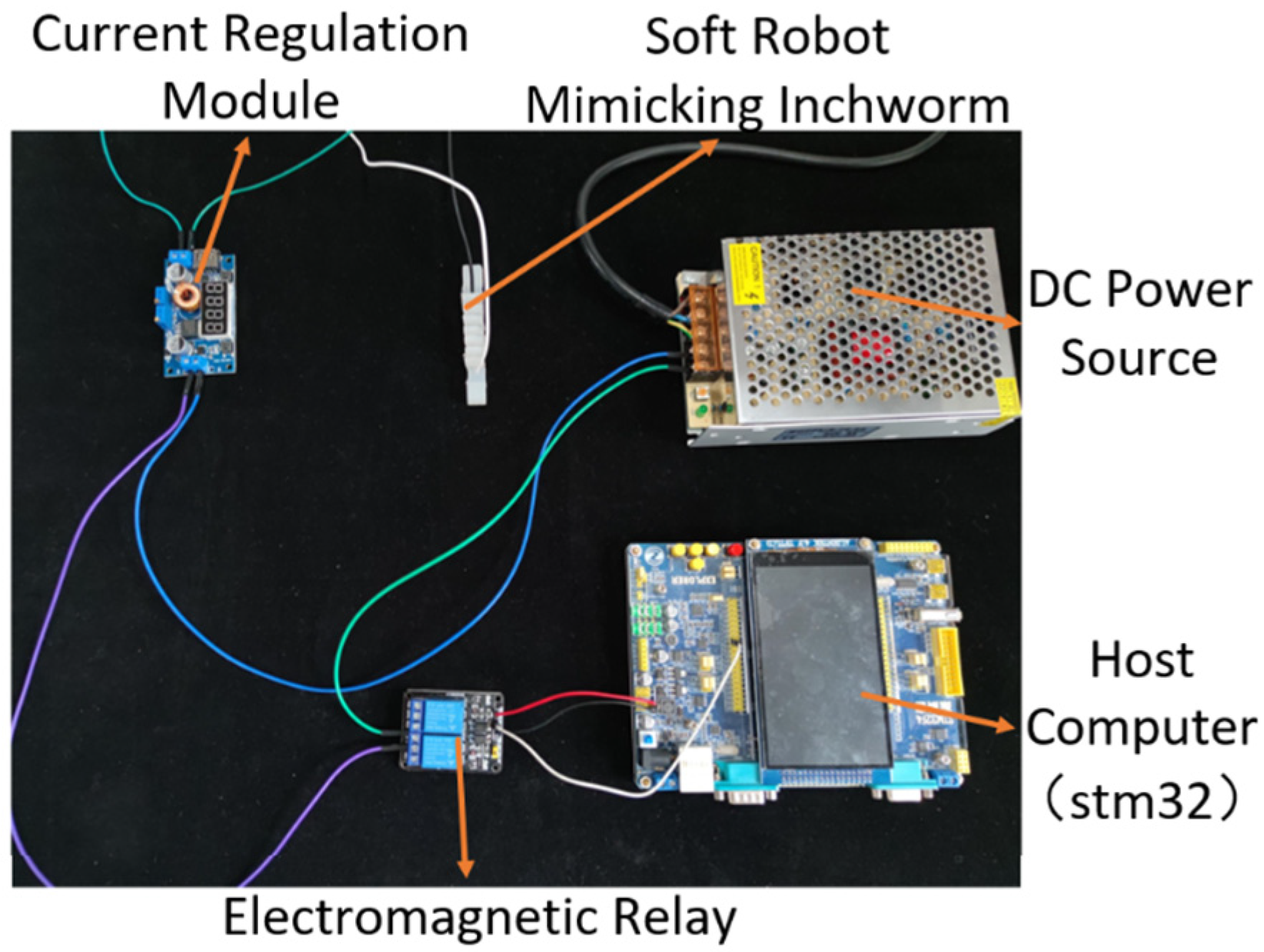
The experimental platform for inchworm-inspired soft robot is shown in Figure 17.
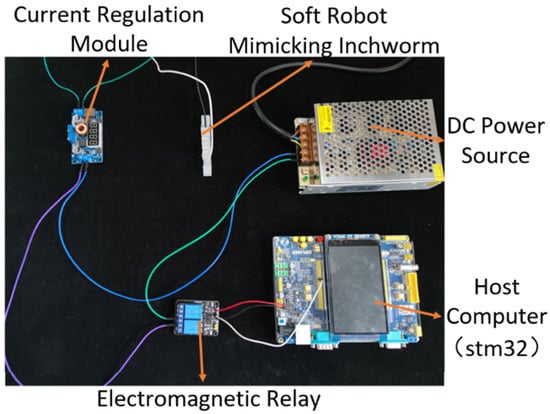
Figure 17.
Open-loop step signal.
The crawling experiment of the inchworm-inspired soft-bodied robot uses a Mos trigger switch relay module as an electronic switch. A 24V3A DC power supply, along with a 5A constant current and constant voltage buck-boost module, is used to input different constant currents into the soft robot. An Stm32 serves as the upper computer, sending a duty cycle of D and a frequency of 1/T square wave current signal to the relay, thereby controlling the crawling movement of the soft robot.
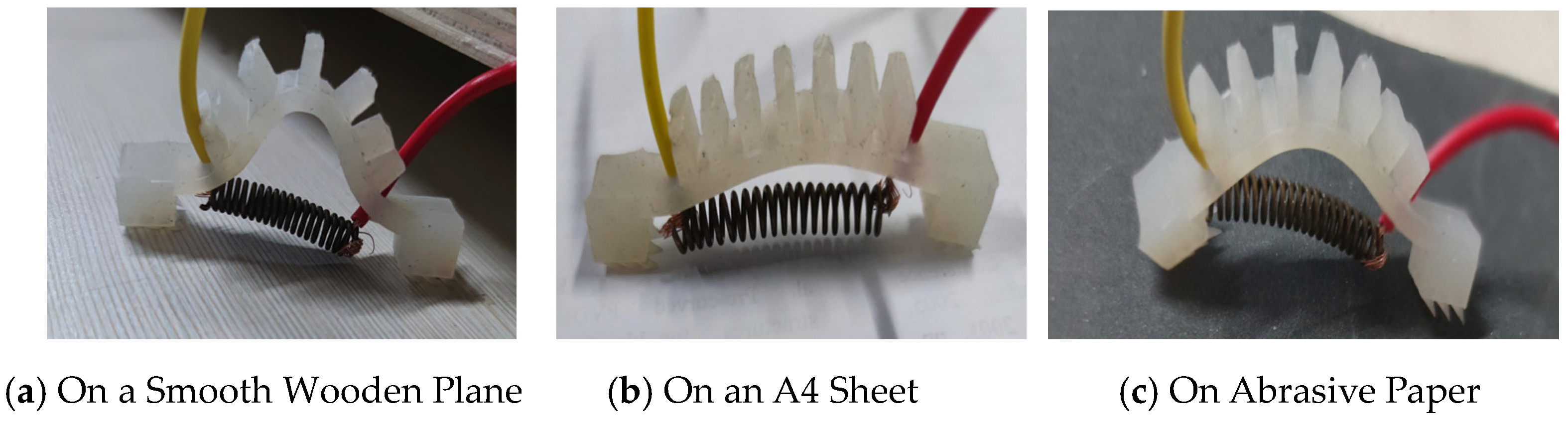
This study experimentally tests the crawling efficiency of the soft robot on different surfaces and with different input currents, as shown in Figure 18. The tested surfaces include a smooth wooden surface, A4 paper, and rough 130-grit sandpaper. The constant current module is used to adjust the input constant current value, and a ruler and camera are used to record the crawling time and displacement of the soft robot. The study records the crawling behavior of the soft robot over one cycle on different surfaces.

Figure 18.
Surface assessment for soft robot.
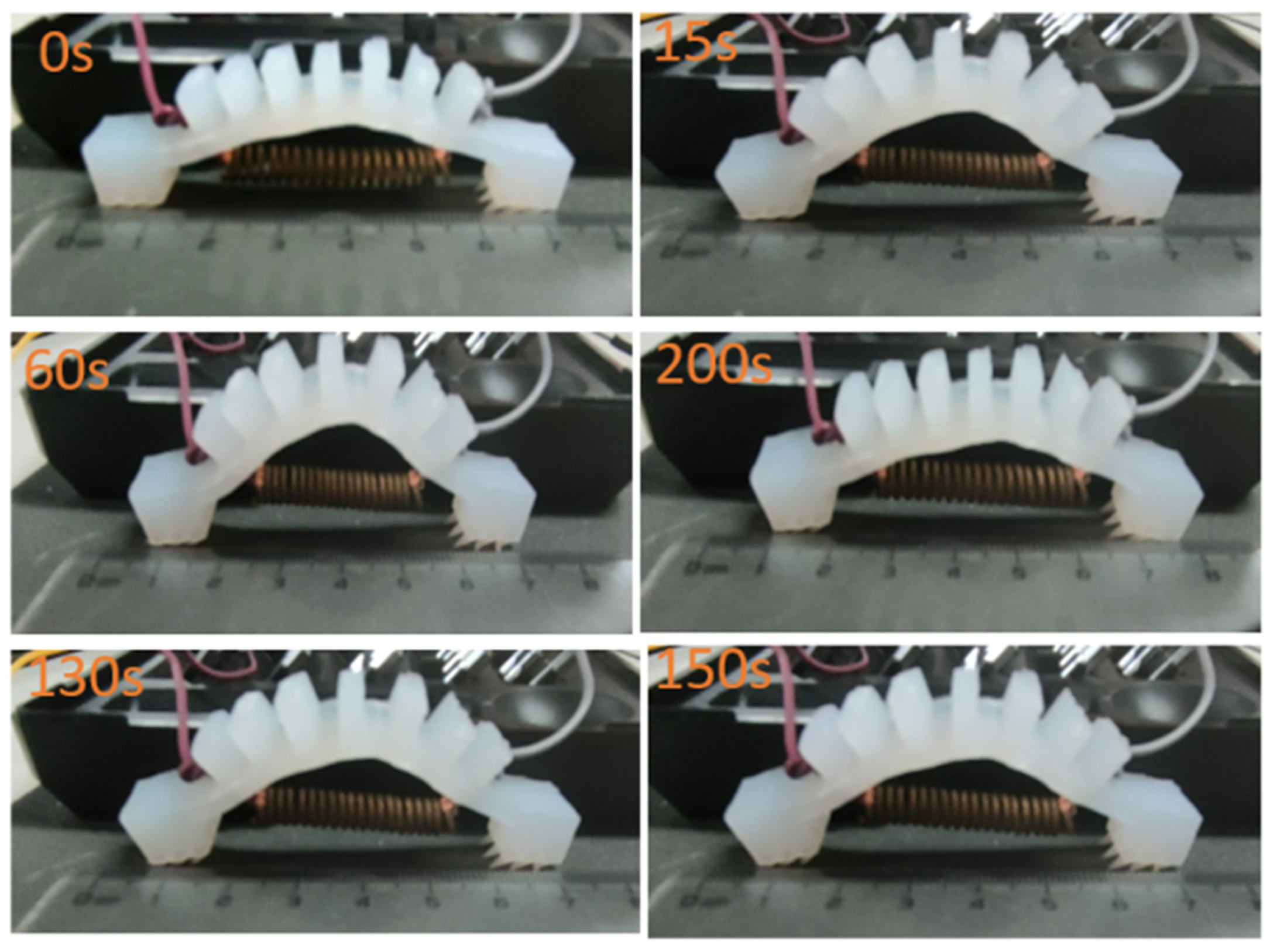
As shown in Figure 19, the crawling process of the centipede-like soft robot on sandpaper for one cycle is illustrated. The SMA actuator used has a diameter of 6 mm and a wire diameter of 1.0 mm. The power is supplied through a constant current module with an input of 4A constant current and a duty cycle of 0.25. The soft robot is in the state of SMA spring contraction from 0 s to 60 s. At this time, the right foot of the soft robot hardly moves, and the left foot moves from 0 on the ruler to 0.9. From 60 s to 240 s, the left foot will move slightly to scale 1 due to inertia, and the right foot will move from scale 7 to 7.8. The test results indicate that under these conditions, the centipede-like soft robot’s speed of motion for one cycle is 0.041 mm/s, with a displacement of 8.1 mm.
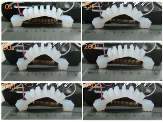
Figure 19.
Motion of soft robot on sandpaper surface for one cycle.
Due to the thermal inertia of SMA materials, it can be observed that the SMA actuator has a very long dissipation time during the driving process. To address the issue of long dissipation time, various heat dissipation methods need to be designed in the future to improve the crawling efficiency of the soft robot. Firstly, the use of small heat sinks, by increasing the surface area for dissipation, can accelerate the dissipation of heat. Secondly, installing temperature sensors on SMA springs and designing a closed-loop feedback control system to monitor and maintain the temperature of the SMA material within a specific phase transition range, ensuring an appropriate working temperature during the shape-changing process, and reducing the process of energy conversion into heat. Thirdly, using low-temperature SMA materials to manufacture SMA actuators, by selecting materials with lower phase transition temperatures, can effectively reduce the amount of energy converted into heat. The combined application of these strategies is expected to significantly shorten the dissipation time of the soft robot and enhance its overall performance.
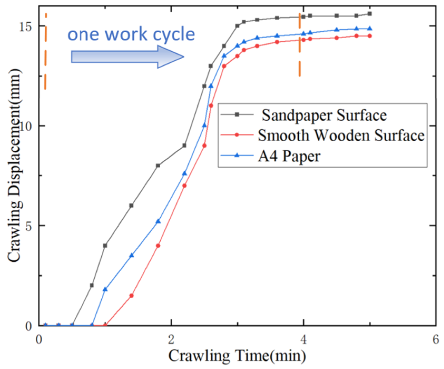
The simulated caterpillar-type soft robot crawled on wooden surface, A4 paper, and sandpaper, starting from the 0 mark on the ruler. The experiment results were recorded with a camera, and the results were plotted as a curve of crawling displacement over time, as shown in Figure 20.
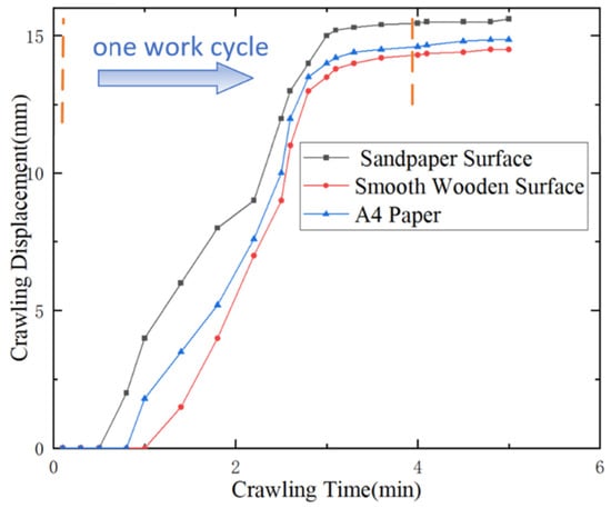
Figure 20.
Soft robot on different plane displacement–time curves.
The experimental results indicate that when the soft robot is electrically heated with SMA, the hind leg moves forward, and the front leg moves slightly backward, resulting in no crawling displacement. When the SMA is powered off and dissipates heat, the front leg begins to move forward, and crawling displacement begins. After the front leg speed reaches 0, due to the elasticity of the SMA spring and the inertia of the soft robot, the soft robot will still move slightly forward. On the sandpaper surface, the friction between the front and rear legs is greater, resulting in better frictional differences. Therefore, the crawling speed on the frictional surface is faster than on the other two surfaces.
6. Conclusions
(1) Based on the kinematic mechanism of inchworms, the characteristics of SMA springs are utilized to design an SMA actuator that mimics the “bending” and “contracting” functions of inchworm muscles. Silicone is used as the body of the soft robot, and the feet are designed with conical friction feet to achieve friction differences between the front and rear feet when SMA is powered on, simulating the adhesion function of inchworms. A prototype of the inchworm-inspired soft robot has been prepared.
(2) Using the Taylor series, a simplified constitutive model for SMA-driven systems is derived. This model, in comparison to traditional models, avoids parameters such as martensite volume and austenite volume that are difficult to directly measure in the laboratory. The constitutive model directly constructs the relationship between strain, temperature, and stress for the SMA actuator. An experimental platform is set up to solve the undetermined parameters of the simplified constitutive model. Tools such as Origin are used to verify the correctness of the derived constitutive model. The results show that the derived constitutive model is in good agreement with experimental results.
(3) We established a multi-field coupled kinematic model for the inchworm-inspired soft robot considering electrical, thermal, and mechanical aspects. We summarized and derived the thermodynamic equation, constitutive model, phase transition dynamics equation, and kinematic equation for the inchworm-inspired soft robot. We used Simulink to simulate the established model, analyze simulation results, compare them with experimental results, and analyze the motion characteristics of the soft robot.
(4) We established an experimental platform to test the crawling motion of the soft robot on smooth wooden surfaces, A4 paper, and sandpaper. We recorded experimental results with a camera and plot displacement-time curves for different surfaces. We compared these curves with simulation curves and physical facts. The comparison shows a basic conformity to physical laws. Experimental results demonstrate that the soft robot can perform continuous crawling motion. The established kinematic model aligns with the experimental situation, indicating its rationality. This work serves as a reference for future modelling and design of soft crawling robots.
(5) The inchworm-inspired soft-bodied robot designed in this paper was compared with the soft-bodied robots mentioned in the introduction. Due to the use of only SMA springs for propulsion, the size is smaller, conforming to the biological image of the inchworm. The driving part utilizes the smart material SMA, which, compared to other smart materials, can be driven using only a DC power supply and wires, making the control conditions simpler and more manageable. Furthermore, a complete kinematic model is established, laying the foundation for various parameter closed-loop controls for the soft-bodied robot in the future. The construction of a new constitutive model for handling SMA materials provides a reference model for researchers who will use SMA materials as drivers in the future.
Author Contributions
Conceptualization, Q.W.; Methodology, Q.W.; Validation, Q.W.; Formal analysis, D.K., Z.S. and Y.Z.; Investigation, Z.S. and Z.W.; Data curation, Z.W.; Writing original draft, D.K.; Writing review & editing, D.K.; Visualization, Z.S.; Supervision, D.Z.; Project administration, Y.Z. and D.Z. All authors have read and agreed to the published version of the manuscript.
Funding
This research was funded by National Natural Science Foundation of China: 51905159 and 52075152; Hubei Provincial Key Research and Development Program: 2022BBA0016.
Data Availability Statement
Data are contained within the article.
Conflicts of Interest
The authors declare no conflict of interest.
References
- Elango, N.; Faudzi, A.A.M. A review article: Investigations on soft materials for soft robot manipulations. Int. J. Adv. Manuf. Technol. 2005, 80, 1027–1037. [Google Scholar] [CrossRef]
- Pinskier, J.; Howard, D. From Bioinspiration to Computer Generation: Developments in Autonomous Soft Robot Design. Adv. Intell. Syst. 2022, 4, 2100086. [Google Scholar] [CrossRef]
- Xu, L.; Wagner, R.J.; Liu, S.; He, Q.; Li, T.; Pan, W.; Feng, Y.; Feng, H.; Meng, Q.; Zou, X. Locomotion of an untethered, worm-inspired soft robot driven by a shape-memory alloy skeleton. Sci. Rep. 2022, 12, 12392. [Google Scholar] [CrossRef] [PubMed]
- Laschi, C.; Cianchetti, M.; Mazzolai, B.; Margheri, L.; Follador, M.; Dario, P. Soft Robot Arm Inspired by the Octopus. Adv. Robot. 2012, 26, 709–727. [Google Scholar] [CrossRef]
- Pang, Y.; Xu, X.; Chen, S.; Fang, Y.; Shi, X.; Deng, Y.; Wang, Z.-L.; Cao, C. Skin-inspired textile-based tactile sensors enable multifunctional sensing of wearables and soft robots. Nano Energy 2022, 96, 107137. [Google Scholar] [CrossRef]
- Yang, X.; Chen, Y.; Zhang, X.; Xue, P.; Lv, P.; Yang, Y.; Wang, L.; Feng, W. Bioinspired light-fueled water-walking soft robots based on liquid crystal network actuators with polymerizable miniaturized gold nanorods. Nano Today 2022, 43, 101419. [Google Scholar] [CrossRef]
- Joey, Z.G.; Calderón, A.A.; Pérez-Arancibia, N.O. An earthworm-inspired soft crawling robot controlled by friction. In Proceedings of the 2017 IEEE International Conference on Robotics and Biomimetics (ROBIO), Macau, China, 5–8 December 2017; pp. 834–841. [Google Scholar]
- Joyee, E.B.; Pan, Y. A fully three-dimensional printed inchworm-inspired soft robot with magnetic actuation. Soft Robot. 2019, 6, 333–345. [Google Scholar] [CrossRef] [PubMed]
- Wang, W.; Lee, J.-Y.; Rodrigue, H.; Song, S.-H.; Chu, W.-S.; Ahn, S.-H. Locomotion of inchworm-inspired robot made of smart soft composite (SSC). Bioinspir. Biomim. 2014, 9, 46006. [Google Scholar] [CrossRef] [PubMed]
- Yang, Y.; Tse, Y.A.; Zhang, Y.; Kan, Z.; Wang, M.Y. A low-cost inchworm-inspired soft robot driven by supercoiled polymer artificial muscle. In Proceedings of the 2019 2nd IEEE International Conference on Soft Robotics (RoboSoft), Seoul, Republic of Korea, 14–18 April 2019; pp. 161–166. [Google Scholar]
- Zhang, Y.; Yang, D.; Yan, P.; Zhou, P.; Zou, J.; Gu, G. Inchworm inspired multimodal soft robots with crawling, climbing, and transitioning locomotion. IEEE Trans. Robot. 2021, 38, 1806–1819. [Google Scholar] [CrossRef]
- Cao, J.; Qin, L.; Liu, J.; Ren, Q.; Foo, C.C.; Wang, H.; Lee, H.P.; Zhu, J. Untethered soft robot capable of stable locomotion using soft electrostatic actuators. Extrem. Mech. Lett. 2018, 21, 9–16. [Google Scholar] [CrossRef]
- Malley, M.; Rubenstein, M.; Nagpal, R. Flippy: A soft, autonomous climber with simple sensing and control. In Proceedings of the 2017 IEEE/RSJ International Conference on Intelligent Robots and Systems (IROS), Vancouver, BC, Canada, 24–28 September 2017; pp. 6533–6540. [Google Scholar]
- Koh, J.-S.; Cho, K.-J. Omega-shaped inchworm-inspired crawling robot with large-index-and-pitch (LIP) SMA spring actuators. IEEE/ASME Trans. Mechatron. 2012, 18, 419–429. [Google Scholar] [CrossRef]
- Ning, J.; Ti, C.; Liu, Y. Inchworm inspired pneumatic soft robot based on friction hysteresis. J. Robot. Autom. 2017, 1, 54–63. [Google Scholar]
- Chen, X.; Stegagno, P.; Yuan, C. A cable-driven switching-legged inchworm soft robot: Design and testing. In Proceedings of the 2021 American Control Conference (ACC), New Orleans, LA, USA, 25–28 May 2021; pp. 2–7. [Google Scholar]
- Must, I.; Kaasik, F.; Põldsalu, I.; Mihkels, L.; Johanson, U.; Punning, A.; Aabloo, A. Ionic and capacitive artificial muscle for biomimetic soft robotics. Adv. Eng. Mater. 2015, 17, 84–94. [Google Scholar] [CrossRef]
- Umedachi, T.; Vikas, V.; Trimmer, B.A. Highly deformable 3-D printed soft robot generating inching and crawling locomotions with variable friction legs. In Proceedings of the 2013 IEEE/RSJ International Conference on Intelligent Robots and Systems, Tokyo, Japan, 3–7 November 2013; pp. 4590–4595. [Google Scholar]
- Wang, J.; Chortos, A. Control Strategies for Soft Robot Systems. Adv. Intell. Syst. 2022, 4, 2100165. [Google Scholar] [CrossRef]
- Mengaldo, G.; Renda, F.; Brunton, S.L.; Bächer, M.; Calisti, M.; Duriez, C.; Chirikjian, G.S.; Laschi, C. A concise guide to modelling the physics of embodied intelligence in soft robotics. Nat. Rev. Phys. 2022, 4, 595–610. [Google Scholar] [CrossRef]
- Seelecke, S.; Muller, I. Shape memory alloy actuators in smart structures: Modeling and simulation. Appl. Mech. Rev. 2004, 57, 23–46. [Google Scholar] [CrossRef]
- Brinson, L.C.; Huang, M.S. Simplifications and comparisons of shape memory alloy constitutive models. J. Intell. Mater. Syst. Struct. 1996, 7, 108–114. [Google Scholar] [CrossRef]
- Cao, J.; Liang, W.; Ren, Q.; Gupta, U.; Chen, F.; Zhu, J. Modelling and control of a novel soft crawling robot based on a dielectric elastomer actuator. In Proceedings of the 2018 IEEE International Conference on Robotics and Automation (ICRA), Brisbane, QLD, Australia, 21–25 May 2018; pp. 4188–4193. [Google Scholar]
- Schegg, P.; Duriez, C. Review on generic methods for mechanical modelling, simulation and control of soft robots. PLoS ONE 2022, 17, e0251059. [Google Scholar] [CrossRef] [PubMed]

Disclaimer/Publisher’s Note: The statements, opinions and data contained in all publications are solely those of the individual author(s) and contributor(s) and not of MDPI and/or the editor(s). MDPI and/or the editor(s) disclaim responsibility for any injury to people or property resulting from any ideas, methods, instructions or products referred to in the content. |
© 2024 by the authors. Licensee MDPI, Basel, Switzerland. This article is an open access article distributed under the terms and conditions of the Creative Commons Attribution (CC BY) license (https://creativecommons.org/licenses/by/4.0/).