
Flexible Pressure and Temperature Microsensors for Textile-Integrated Wearables

 , ,
, ,  ,
,  , ,
, ,  , , , and
Abstract
1. Introduction
2. Design and Fabrication
2.1. Sensors Design and Modeling
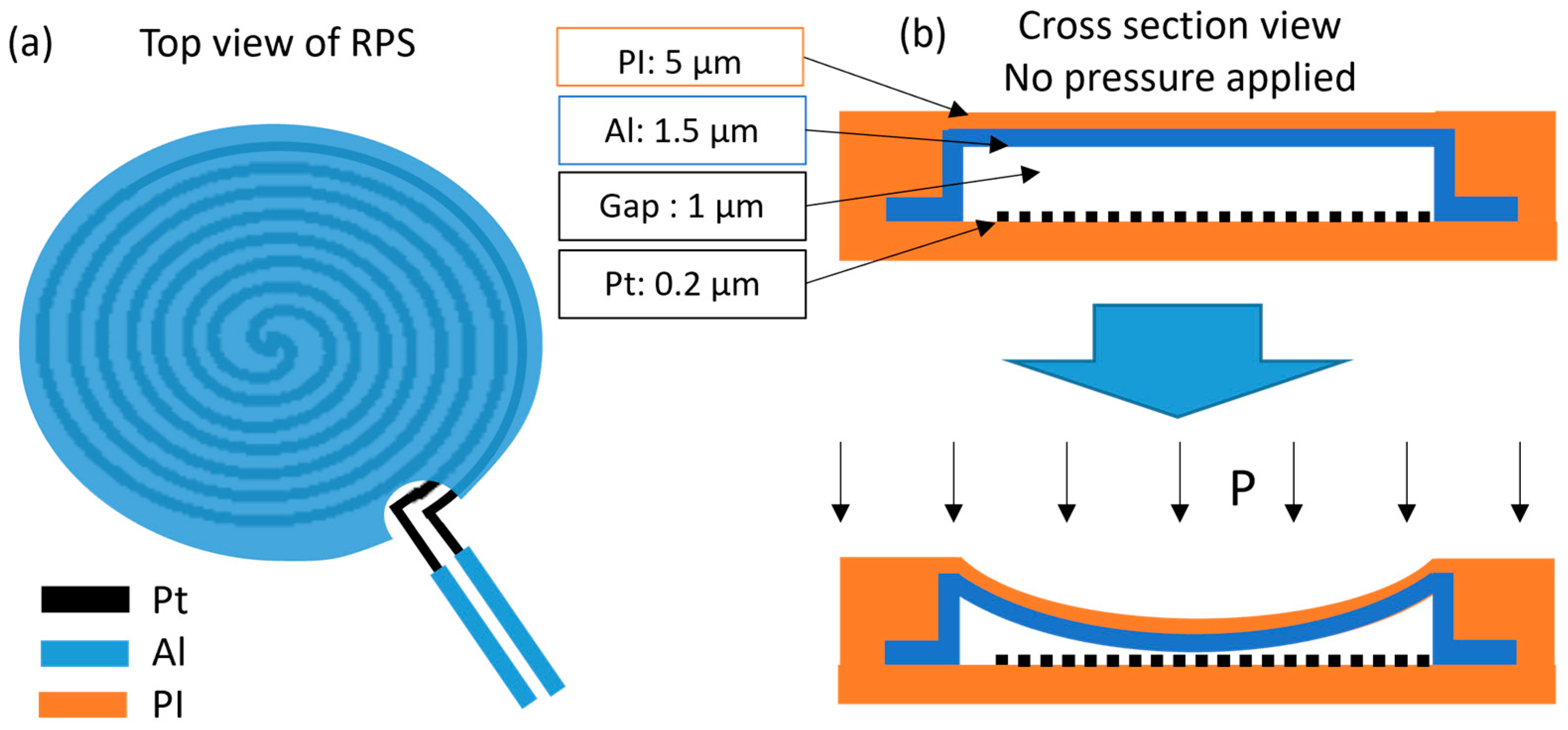
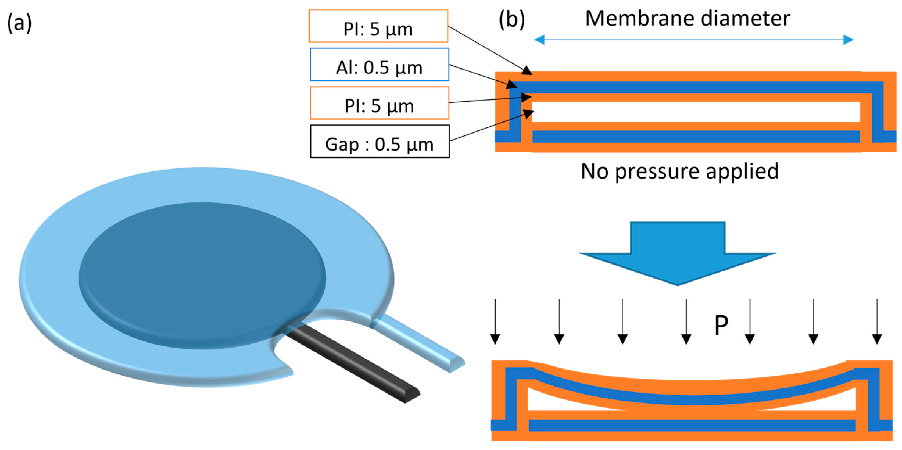
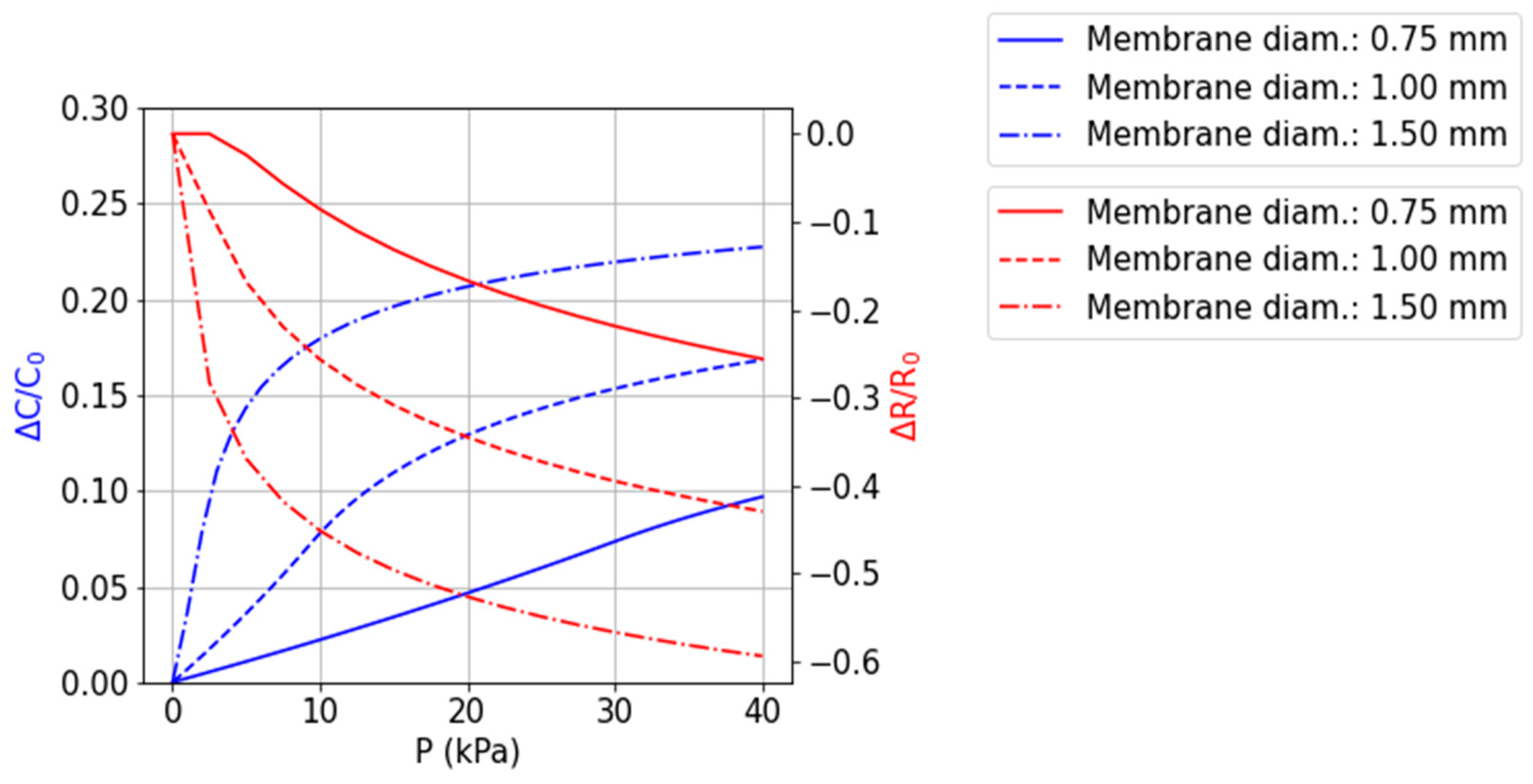
2.1.1. Pressure Sensors
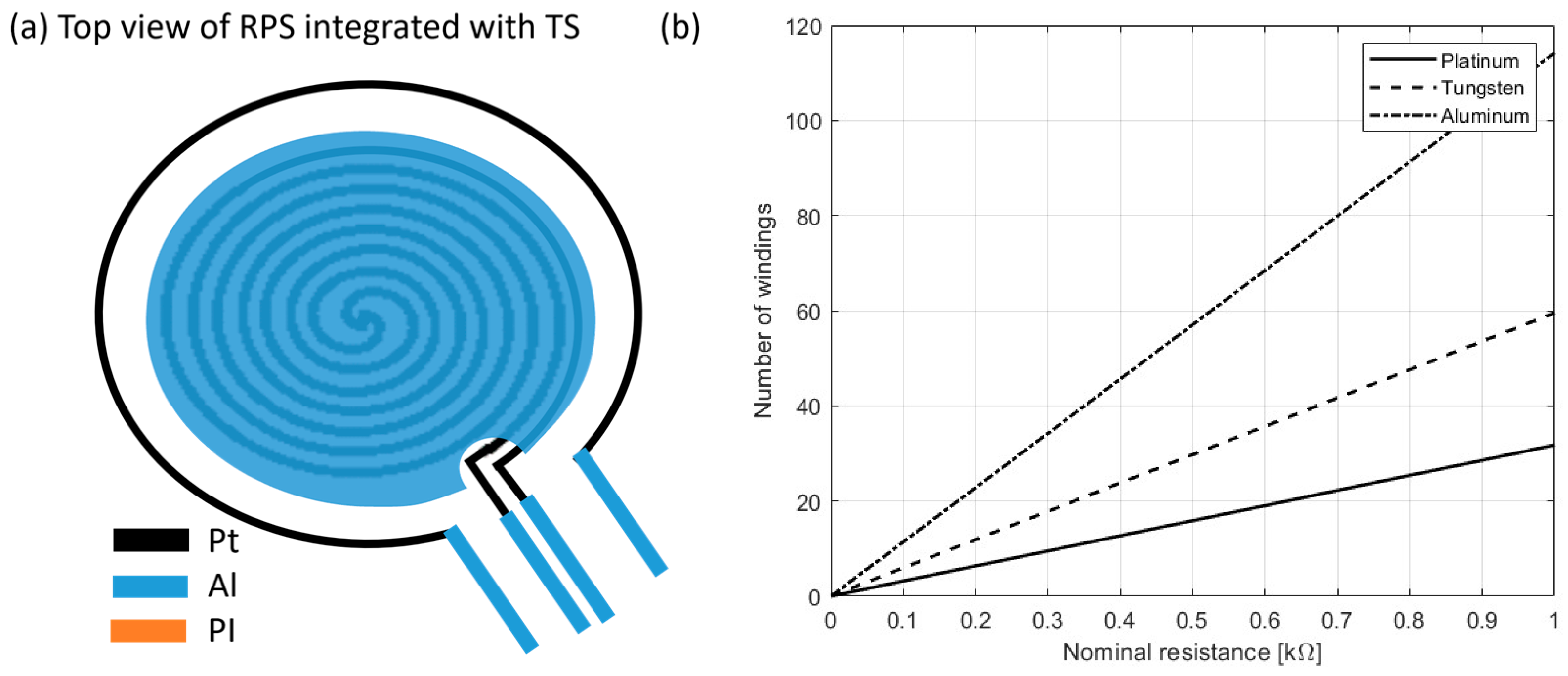
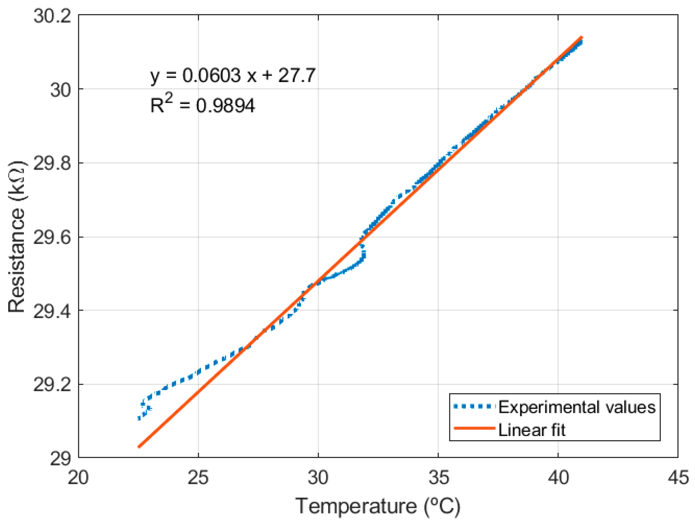
2.1.2. Resistance Temperature Detectors (RTDs)
2.2. Sensor Microfabrication and Textile Integration
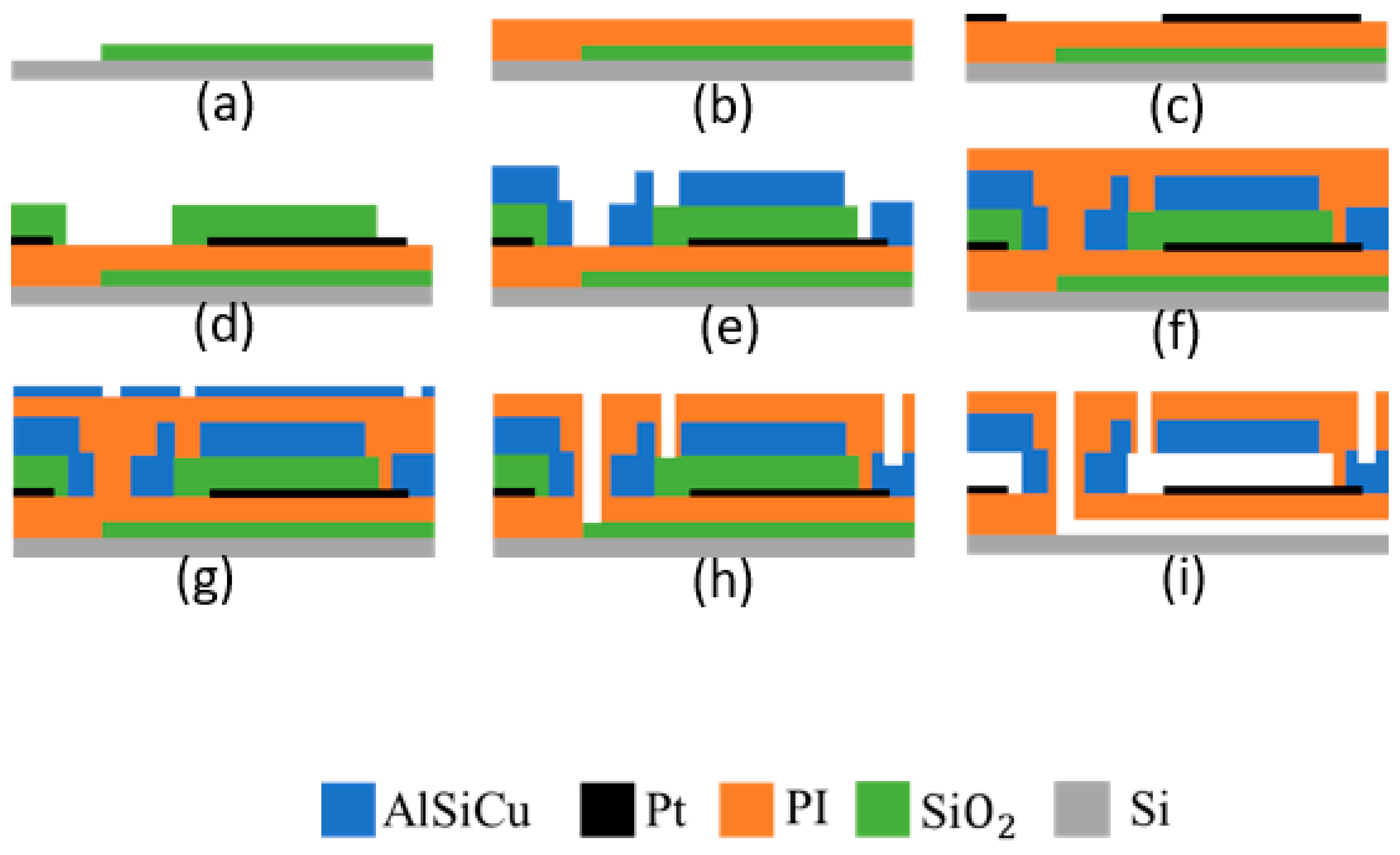
2.2.1. Microfabrication Process Flow
- (a)
- SiO2 deposition (by PE-CVD) on silicon substrate;
- (b)
- Spin coating of 1st layer of 5 µm of PI;
- (c)
- Bottom electrode metal sputtering and patterning by lithography followed by RIE;
- (d)
- Spin coating of 2nd layer of 5 µm of PI;
- (e)
- SiO2 deposition and patterning by lithography and RIE;
- (f)
- Spin coating of 3rd layer of 5 µm of PI;
- (g)
- Top electrode metal (AlSiCu and TiW multilayer) deposition and patterning by lithography and RIE;
- (h)
- Spin coating of 4th (and last) of 5 µm of PI;
- (i)
- Metal hard mask (AlSiCu and TiW bilayer, 600 nm total thickness) deposition and patterning;
- (j)
- PI RIE and hard mask wet etch;
- (k)
- HF vapor release.
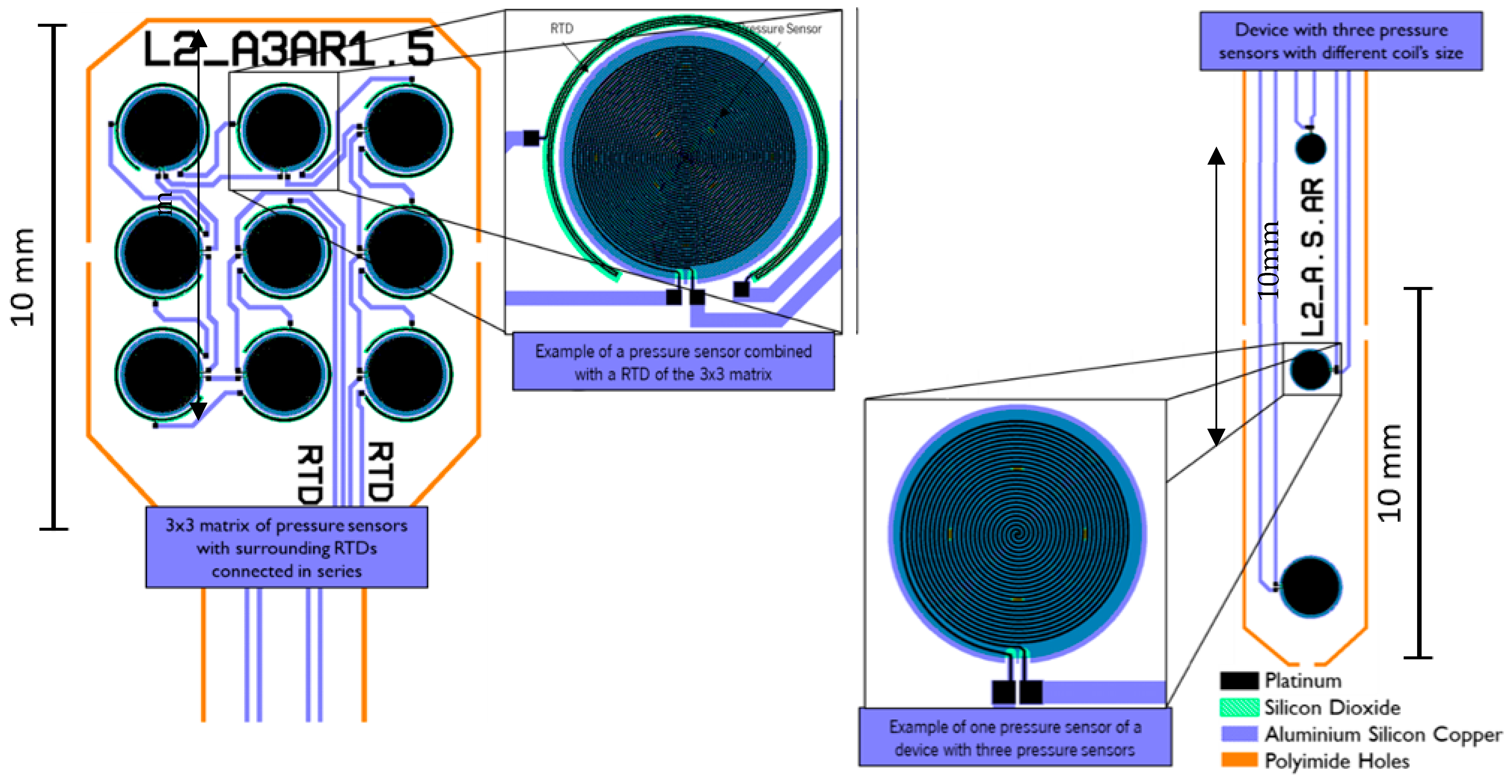
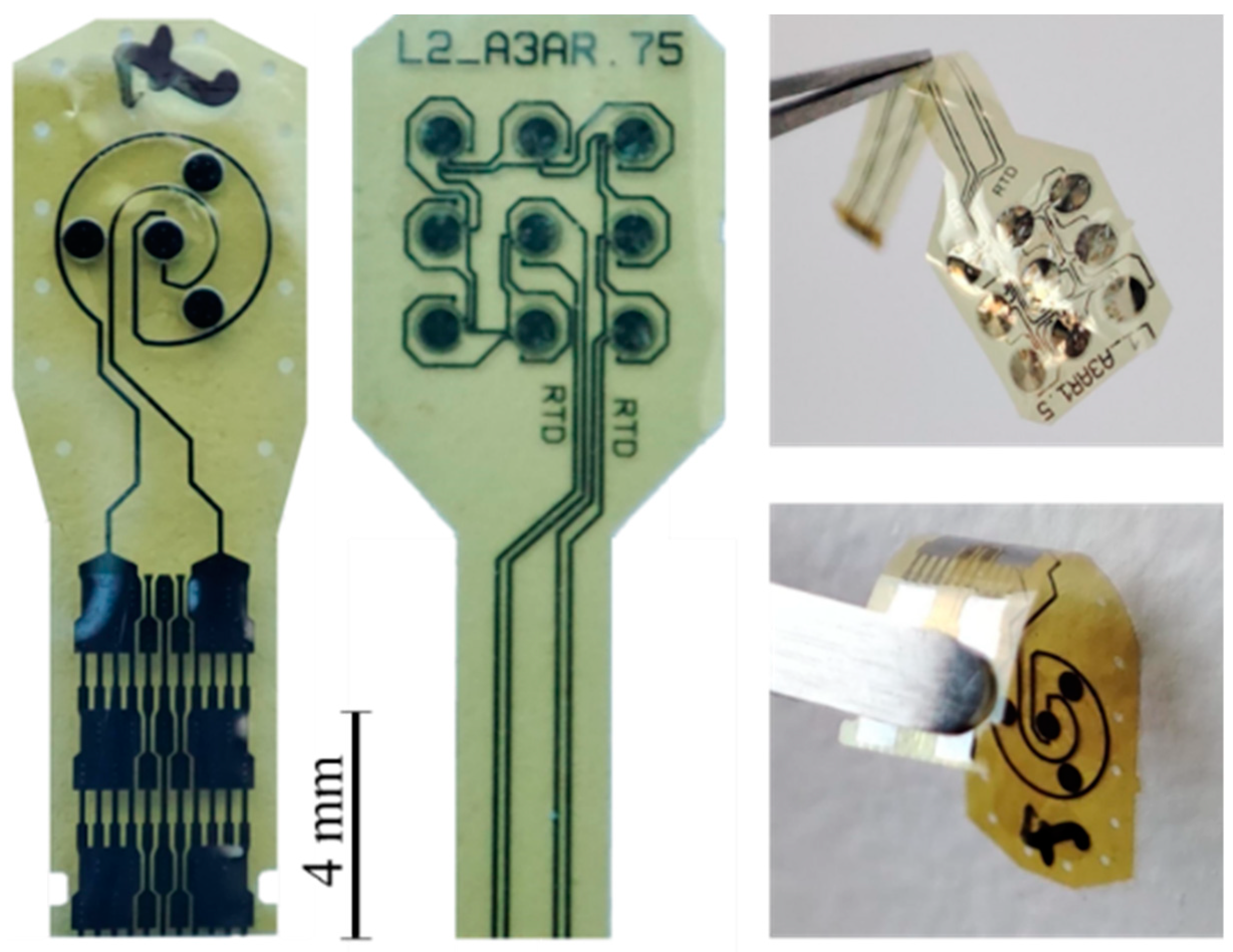
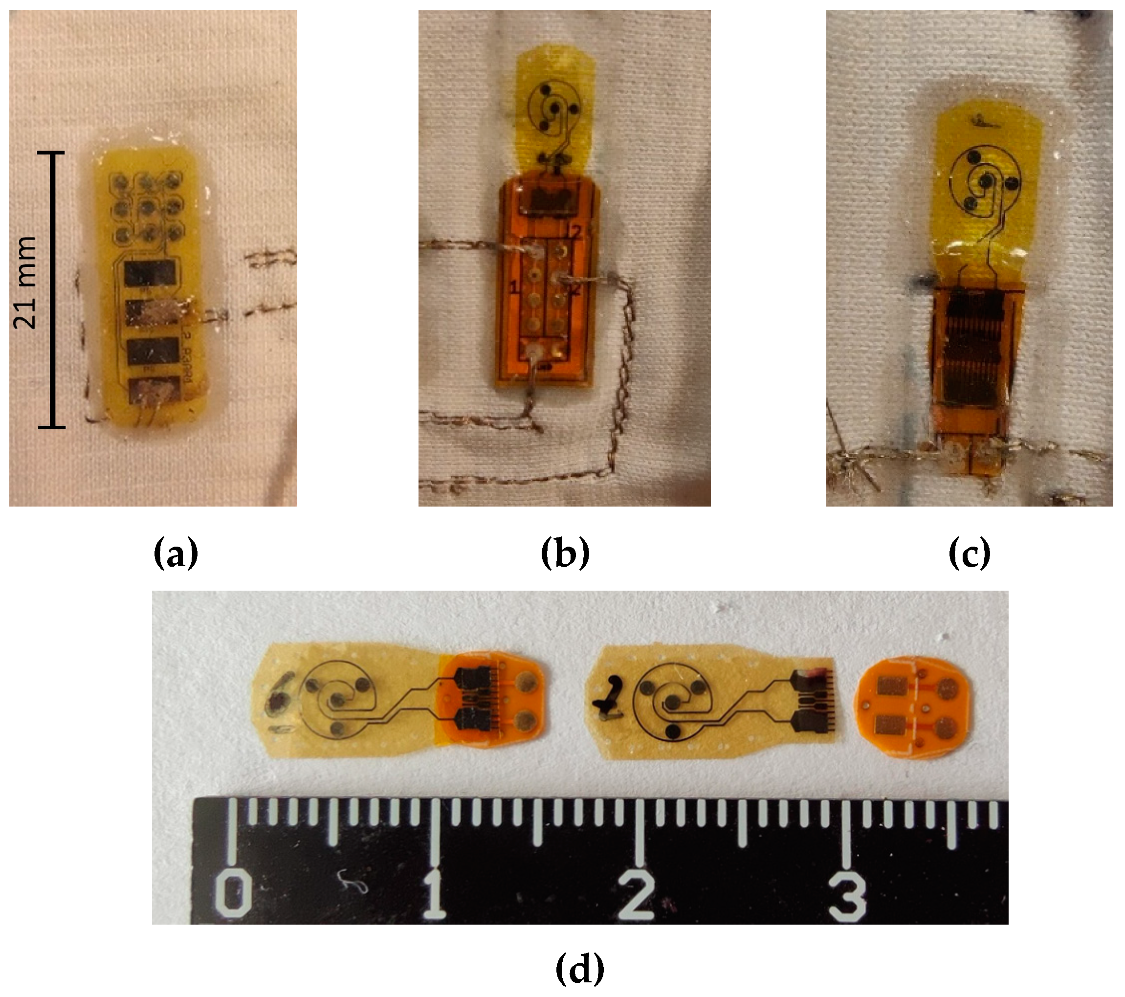
2.2.2. Layouts and Fabricated Sensors
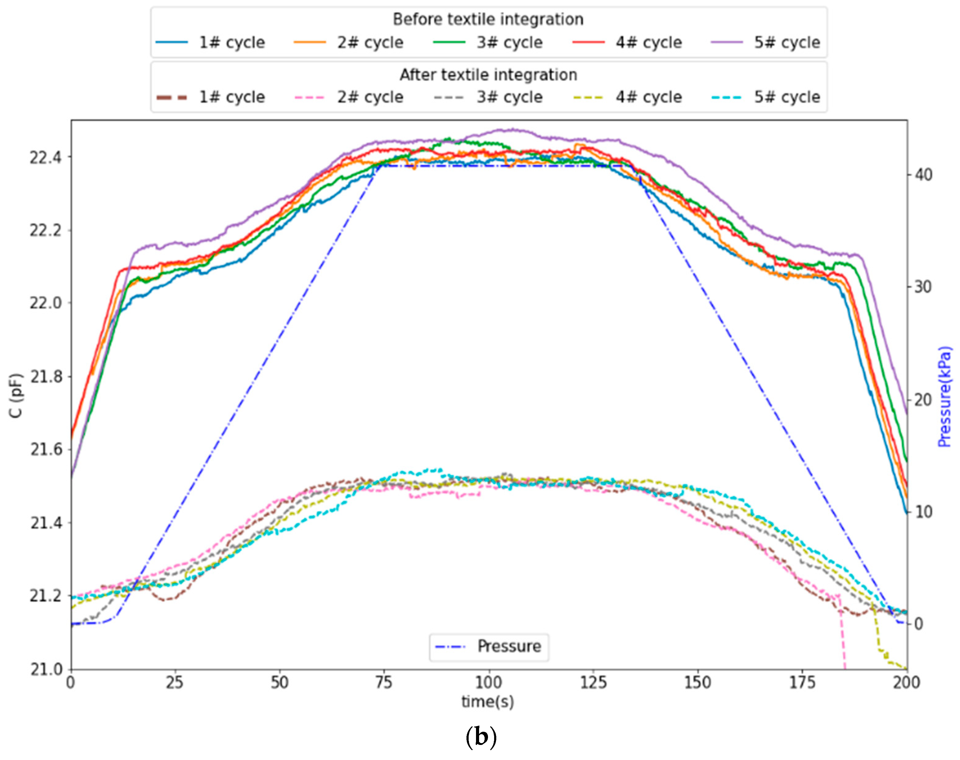
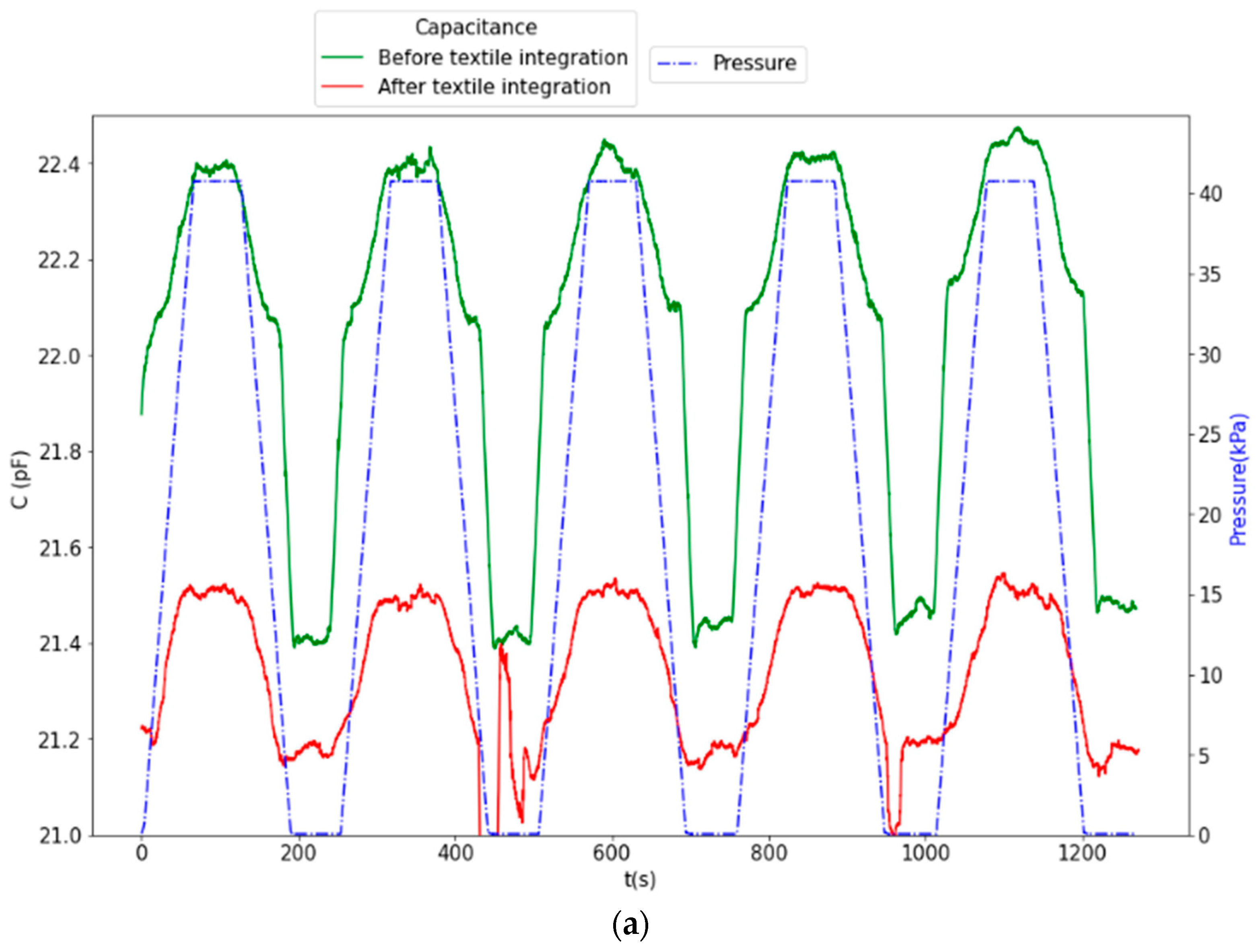
2.2.3. Textile Integration
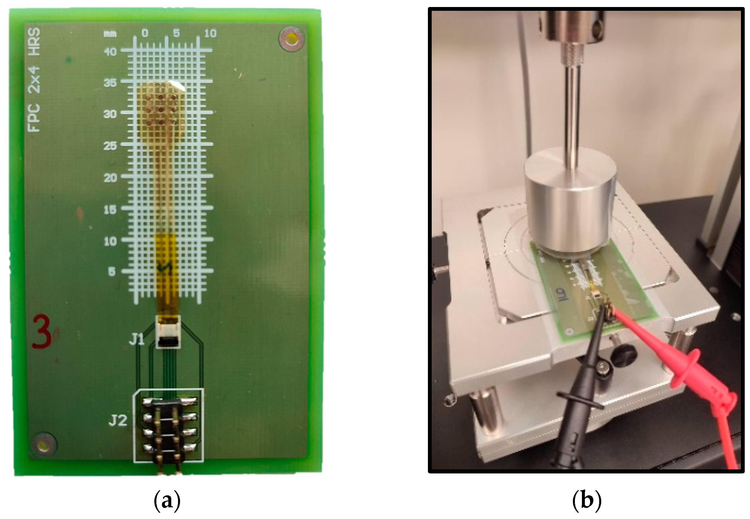
2.3. Experimental Setup for Sensor Characterization
3. Results and Discussion
4. Conclusions
Author Contributions
Funding
Data Availability Statement
Acknowledgments
Conflicts of Interest
List of Acronyms
| C2D | capacitance to digital |
| CPS | capacitive pressure sensor |
| flexPCB | flexible printed circuit board |
| FPC-FFC | flexible printed circuit–flat flexible cables |
| HF | hydrofluoric acid |
| PCB | printed circuit board |
| PE-CVD | plasma enhanced chemical vapor deposition |
| PI | polyimide |
| RIE | reactive ion etching |
| RPS | resistive pressure sensor |
| RTD | resistive temperature detector |
References
- Chung, M.; Widdel, M.; Kirchhoff, J.; Sellin, J.; Jelali, M.; Geiser, F.; Mücke, M.; Conrad, R. Risk Factors for Pressure Ulcers in Adult Patients: A Meta-analysis on Sociodemographic Factors and the Braden Scale. J. Clin. Nurs. 2022, 32, 1979–1992. [Google Scholar] [CrossRef]
- da Silva Galetto, S.G.; do Nascimento, E.R.P.; Hermida, P.M.V.; Busanello, J.; de Malfussi, L.B.H.; Lazzari, D.D. Medical device-related pressure injuries in critical patients: Prevalence and associated factors. Rev. Da Esc. Enferm. 2021, 55, e20200397. [Google Scholar] [CrossRef] [PubMed]
- Silva, A.; Metrôlho, J.; Ribeiro, F.; Fidalgo, F.; Santos, O.; Dionisio, R. A Review of Intelligent Sensor-Based Systems for Pressure Ulcer Prevention. Computers 2022, 11, 6. [Google Scholar] [CrossRef]
- Marchione, F.G.; Araújo, L.M.Q.; Araújo, L.V. Approaches that use software to support the prevention of pressure ulcer: A systematic review. Int. J. Med. Inform. 2015, 84, 725–736. [Google Scholar] [CrossRef] [PubMed]
- Jiang, M.; Ma, Y.; Guo, S.; Jin, L.; Lv, L.; Han, L.; An, N. Using Machine Learning Technologies in Pressure Injury Management: Systematic Review. JMIR Med. Inf. 2021, 9, e25704. [Google Scholar] [CrossRef] [PubMed]
- Knitronix. Available online: https://www.knitronix.com/ (accessed on 14 September 2023).
- Magniez, K.; Krajewski, A.; Neuenhofer, M.; Helmer, R. Effect of drawing on the molecular orientation and polymorphism of melt-spun polyvinylidene fluoride fibers: Toward the development of piezoelectric force sensors. J. Appl. Polym. Sci. 2013, 129, 2699–2706. [Google Scholar] [CrossRef]
- Meng, K.; Xiao, X.; Wei, W.; Chen, G.; Nashalian, A.; Shen, S.; Xiao, X.; Chen, J. Wearable Pressure Sensors for Pulse Wave Monitoring. Adv. Mater. 2022, 34, 2109357. [Google Scholar] [CrossRef]
- Wicaksono, I.; Kodama, E.; Dementyev, A.; Paradiso, J.A. SensorNets: Towards reconfigurable multifunctional fine-grained soft and stretchable electronic skins. In Proceedings of the Extended Abstracts of the 2020 CHI Conference on Human Factors in Computing Systems, Honolulu, HI, USA, 25–30 April 2020; pp. 1–8. [Google Scholar] [CrossRef]
- Atamana, C.; Kinkeldei, T.; Vasquez-Quintero, A.; Molina-Lopez, F.; Courbat, J.; Cherenack, K.; Briand, D.; Tröster, G.; De Rooij, N.F. Humidity and temperature sensors on plastic foil for textile integration. Procedia Eng. 2011, 25, 136–139. [Google Scholar] [CrossRef]
- Mattana, G.; Kinkeldei, T.; Leuenberger, D.; Ataman, C.; Ruan, J.J.; Molina-Lopez, F.; Quintero, A.V.; Nisato, G.; Tröster, G.; Briand, D.; et al. Woven temperature and humidity sensors on flexible plastic substrates for e-textile applications. IEEE Sens. J. 2013, 13, 3901–3909. [Google Scholar] [CrossRef]
- Zysset, C.; Kinkeldei, T.W.; Munzenrieder, N.; Cherenack, K.; Tröster, G. Integration method for electronics in woven textiles. IEEE Trans. Compon. Packag. Manuf. Technol. 2012, 2, 1107–1117. [Google Scholar] [CrossRef]
- Cherenack, K.; Van Pieterson, L. Smart textiles: Challenges and opportunities. J. Appl. Phys. 2012, 112, 091301. [Google Scholar] [CrossRef]
- Cherenack, K.; Zysset, C.; Kinkeldei, T.; Münzenrieder, N.; Tröster, G. Woven electronic fibers with sensing and display functions for smart textiles. Adv. Mater. 2010, 22, 5178–5182. [Google Scholar] [CrossRef] [PubMed]
- Costa, J.C.; Spina, F.; Lugoda, P.; Garcia-Garcia, L.; Roggen, D.; Münzenrieder, N. Flexible Sensors—From Materials to Applications. Technologies 2019, 7, 35. [Google Scholar] [CrossRef]
- Lugoda, P.; Costa, J.C.; Oliveira, C.; Garcia-Garcia, L.A.; Wickramasinghe, S.D.; Pouryazdan, A.; Roggen, D.; Dias, T.; Münzenrieder, N. Flexible temperature sensor integration into e-textiles using different industrial yarn fabrication processes. Sensors 2019, 20, 73. [Google Scholar] [CrossRef] [PubMed]
- Pasahan, A. Sensor Applications of Polyimides. In High Performance Polymers—Polyimides Based—From Chemistry to Applications; IntechOpen: London, UK, 2012. [Google Scholar] [CrossRef]
- Sotgiu, E.; Aguiam, D.E.; Calaza, C.; Rodrigues, J.; Fernandes, J.; Pires, B.; Moreira, E.E.; Alves, F.; Fonseca, H.; Dias, R.; et al. Surface Texture Detection with a New Sub-mm Resolution Flexible Tactile Capacitive Sensor Array for Multimodal Artificial Finger. J. Microelectromechanical Syst. 2020, 29, 629–636. [Google Scholar] [CrossRef]
- Liu, R.; Huang, J.-Q.; Huang, Q.-A. A Capacitive Humidity Sensor Based on an PTFE sSubstrate. Sensors 2017, 17, 1009. [Google Scholar] [CrossRef]
- Dubourg, G.; Segkos, A.; Katona, J.; Radović, M.; Savić, S.; Niarchos, G.; Tsamis, C.; Crnojević-Bengin, V. Fabrication and characterization of flexible and miniaturized humidity sensors using screen-printed TiO2nanoparticles as sensitive layer. Sensors 2017, 17, 1854. [Google Scholar] [CrossRef]
- Constantin, C.P.; Aflori, M.; Damian, R.F.; Rusu, R.D. Biocompatibility of Polyimides: A Mini-Review. Materials 2019, 12, 3166. [Google Scholar] [CrossRef]
- Lee, J.; Kwon, H.; Seo, J.; Shin, S.; Koo, J.H.; Pang, C.; Son, S.; Kim, J.H.; Jang, Y.H.; Kim, D.E.; et al. Conductive fiber-based ultrasensitive textile pressure sensor for wearable electronics. Adv. Mater. 2015, 27, 2433–2439. [Google Scholar] [CrossRef]
- Wu, R.; Ma, L.; Hou, C.; Meng, Z.; Guo, W.; Yu, W.; Yu, R.; Hu, F.; Liu, X.Y. Silk Composite Electronic Textile Sensor for High Space Precision 2D Combo Temperature–Pressure Sensing. Small 2019, 15, e1901558. [Google Scholar] [CrossRef]
- Ma, L.; Liu, Q.; Wu, R.; Meng, Z.; Patil, A.; Yu, R.; Yang, Y.; Zhu, S.; Fan, X.; Hou, C.; et al. From Molecular Reconstruction of Mesoscopic Functional Conductive Silk Fibrous Materials to Remote Respiration Monitoring. Small 2020, 16, e2000203. [Google Scholar] [CrossRef] [PubMed]
- Pouyan, M.B.; Birjandtalab, J.; Heydarzadeh, M.; Nourani, M.; Ostadabbas, S. A pressure map dataset for posture and subject analytics. In Proceedings of the 2017 IEEE EMBS International Conference on Biomedical & Health Informatics (BHI), Orlando, FL, USA, 16–19 February 2017; pp. 65–68. [Google Scholar] [CrossRef]
- Hong, Y.S. Smart Care Beds for Elderly Patients with Impaired Mobility. Wirel. Commun. Mob. Comput. 2018, 2018, 1780904. [Google Scholar] [CrossRef]
- Sakai, K.; Sanada, H.; Matsui, N.; Nakagami, G.; Sugama, J.; Komiyama, C.; Yahagi, N. Continuous monitoring of interface pressure distribution in intensive care patients for pressure ulcer prevention. J. Adv. Nurs. 2009, 65, 809–817. [Google Scholar] [CrossRef] [PubMed]
- Soares, R.S.; Lima, S.B.; Eberhardt, T.D.; Rodrigues, L.R.; Martins, R.S.; Silveira, L.B.; Alves, P.J. Skin temperature as a clinical parameter for nursing care: A descriptive correlational study. J. Wound Care 2019, 28, 835–841. [Google Scholar] [CrossRef] [PubMed]
- Kokate, J.Y.; Leland, K.J.; Held, A.M.; Hansen, G.L.; Kveen, G.L.; Johnson, B.A.; Wilke, M.S.; Sparrow, E.M.; Iaizzo, P.A. Temperature-modulated pressure ulcers: A porcine model. Arch. Phys. Med. Rehabil. 1995, 76, 666–673. [Google Scholar] [CrossRef] [PubMed]
- Linder-Ganz, E.; Gefen, A. The Effects of Pressure and Shear on Capillary Closure in the Microstructure of Skeletal Muscles. Ann. Biomed. Eng. 2007, 35, 2095–2107. [Google Scholar] [CrossRef] [PubMed]
- Lee, C.M.; Jin, S.P.; Doh, E.J.; Lee, D.H.; Chung, J.H. Regional Variation of Human Skin Surface Temperature. Ann. Dermatol. 2019, 31, 349–352. [Google Scholar] [CrossRef]
- Wang, Y.; Zhu, W.; Yu, Y.; Zhu, P.; Song, Q.; Deng, Y. High-Sensitivity Flexible Pressure Sensor with Low Working Voltage Based on Sphenoid Microstructure. IEEE Sens. J. 2020, 20, 7354–7361. [Google Scholar] [CrossRef]
- Chen, Z.; Huang, W.; Zhang, X.; Yuen, M.M.F. A Flexible and Stretchable Resistive Epidermal Pressure Sensor for Health Monitoring. Proc. Electron. Compon. Technol. Conf. 2016, 2016, 1644–1649. [Google Scholar] [CrossRef]
- Geninatti, T.; Bruno, G.; Barile, B.; Hood, R.L.; Farina, M.; Schmulen, J.; Canavese, G.; Grattoni, A. Impedance characterization, degradation, and in vitro biocompatibility for platinum electrodes on BioMEMS. Biomed. Microdevices 2015, 17, 24. [Google Scholar] [CrossRef]
- Plasma Metal Coated Yarns. Available online: https://www.swicofil.com/commerce/basic-information/downloads/plasma-metal-coated-yarn.pdf (accessed on 12 January 2024).
- Steck, D.; Qu, J.; Kordmahale, S.B.; Tscharnuter, D.; Muliana, A.; Kameoka, J. Mechanical responses of Ecoflex silicone rubber: Compressible and incompressible behaviors. J. Appl. Polym. Sci. 2019, 136, 47025. [Google Scholar] [CrossRef]
- Cheng, M.Y.; Lin, C.L.; Lai, Y.T.; Yang, Y.J. A polymer-based capacitive sensing array for normal and shear force measurement. Sensors 2010, 10, 10211–10225. [Google Scholar] [CrossRef] [PubMed]
- Lee, H.K.; Chung, J.; Chang, S., II; Yoon, E. Real-time measurement of the three-axis contact force distribution using a flexible capacitive polymer tactile sensor. J. Micromechanics Microengineering 2011, 21, 035010. [Google Scholar] [CrossRef]
- Dobrzynska, J.A.; Gijs, M.A.M. Flexible polyimide-based force sensor. Sens. Actuators A Phys. 2012, 173, 127–135. [Google Scholar] [CrossRef]
- Wang, Y.C.; Chen, T.Y.; Chen, R.; Lo, C.Y. Mutual capacitive flexible tactile sensor for 3-D image control. J. Microelectromechanical Syst. 2013, 22, 804–814. [Google Scholar] [CrossRef]
- Liang, G.; Wang, Y.; Mei, D.; Xi, K.; Chen, Z. Flexible Capacitive Tactile Sensor Array with Truncated Pyramids as Dielectric Layer for Three-Axis Force Measurement. J. Microelectromechanical Syst. 2015, 24, 1510–1519. [Google Scholar] [CrossRef]
- Chandra, M.; Ke, S.Y.; Chen, R.; Lo, C.Y. Vertically stacked capacitive tactile sensor with more than quadrupled spatial resolution enhancement from planar arrangement. Sens. Actuators A Phys. 2017, 263, 386–390. [Google Scholar] [CrossRef]
- Münzenrieder, N.; Vogt, C.; Petti, L.; Salvatore, G.; Cantarella, G.; Büthe, L.; Tröster, G. Oxide Thin-Film Transistors on Fibers for Smart Textiles. Technologies 2017, 5, 31. [Google Scholar] [CrossRef]
- Zysset, C.; Münzenrieder, N.; Kinkeldei, T.; Cherenack, K.; Tröster, G. Woven active-matrix display. IEEE Trans. Electron Devices 2012, 59, 721–728. [Google Scholar] [CrossRef]
- Rêgo, A.S.; Filipe, L.; Dias, R.A.; Alves, F.S.; Queiroz, J.; Ainla, A.; Arruda, L.M.; Fangueiro, R.; Bouçanova, M.; Bernardes, R.A.; et al. End-User Assessment of an Innovative Clothing-Based Sensor Developed for Pressure Injury Prevention: A Mixed-Method Study. Int. J. Environ. Res. Public Health 2023, 20, 4039. [Google Scholar] [CrossRef]
- Jung, T.M.; Jang, D.J.; Lee, J.H. The Novel Digital Therapeutics Sensor and Algorithm for Pressure Ulcer Care Based on Tissue Impedance. Sensors 2023, 23, 3620. [Google Scholar] [CrossRef] [PubMed]
- Agueda, J.R.S.; Lim, J.; Mondragon, J.M.; Madrid, J.; Belen, M.G.; Eustaquio, G.M.Y.; Monjardin, J.G.; Salud, N. Rapid prototyping of a temperature, humidity, and pressure monitor electronic layer for Pressure Ulcer wound patch. J. Phys. Conf. Ser. 2021, 2071, 012024. [Google Scholar] [CrossRef]
- Lin, Y.H.; Chen, Y.C.; Cheng, K.S.; Yu, P.J.; Wang, J.L.; Ko, N.Y. Higher periwound temperature associated with wound healing of pressure ulcers detected by infrared thermography. J. Clin. Med. 2021, 10, 2883. [Google Scholar] [CrossRef] [PubMed]
- Pickham, D.; Berte, N.; Pihulic, M.; Valdez, A.; Mayer, B.; Desai, M. Effect of a wearable patient sensor on care delivery for preventing pressure injuries in acutely ill adults: A pragmatic randomized clinical trial (LS-HAPI study). Int. J. Nurs. Stud. 2018, 80, 12–19. [Google Scholar] [CrossRef]


| Work | Measurement Mechanism/ Change | Pressure/Force Range | Sensitivity | Note |
|---|---|---|---|---|
| E.Sotgiu et al. [18] | interelectrode spacing | 30 kPa, 80 kPa | 1, 0.43 fF/kPa (bare) | Flexible PI-based device, bare or PDMS coated |
| M.Y. Cheng et al. [37] | interelectrode spacing | 0.1 N | ∼1.67%/mN | Measuring normal/shear force, PDMS |
| H.-K. Lee et al. [38] | interelectrode spacing | 250 kPa | 1.2–1.3%/mN | Measuring normal/shear force, PDMS |
| J. Dobrzynska et al. [39] | interelectrode spacing | 100 N | 0.5–1 fF/N | Finger-like microstructures, PI, no air gap |
| Y.-C. Wang et al. [40] | interelectrode spacing | 10 kPa | 1.9 pF/N | A mutual capacitive touch panel, PET/PDMS |
| G. Liang et al. [41] | interelectrode spacing | 0.5 N, 4 N | ∼67.2, 7.7%/N | Measuring normal/shear force, PDMS |
| M. Chandra et al. [42] | overlap area | 2 N | ∼0.08 pF/N | Measuring normal/shear force, PET/PDMS |
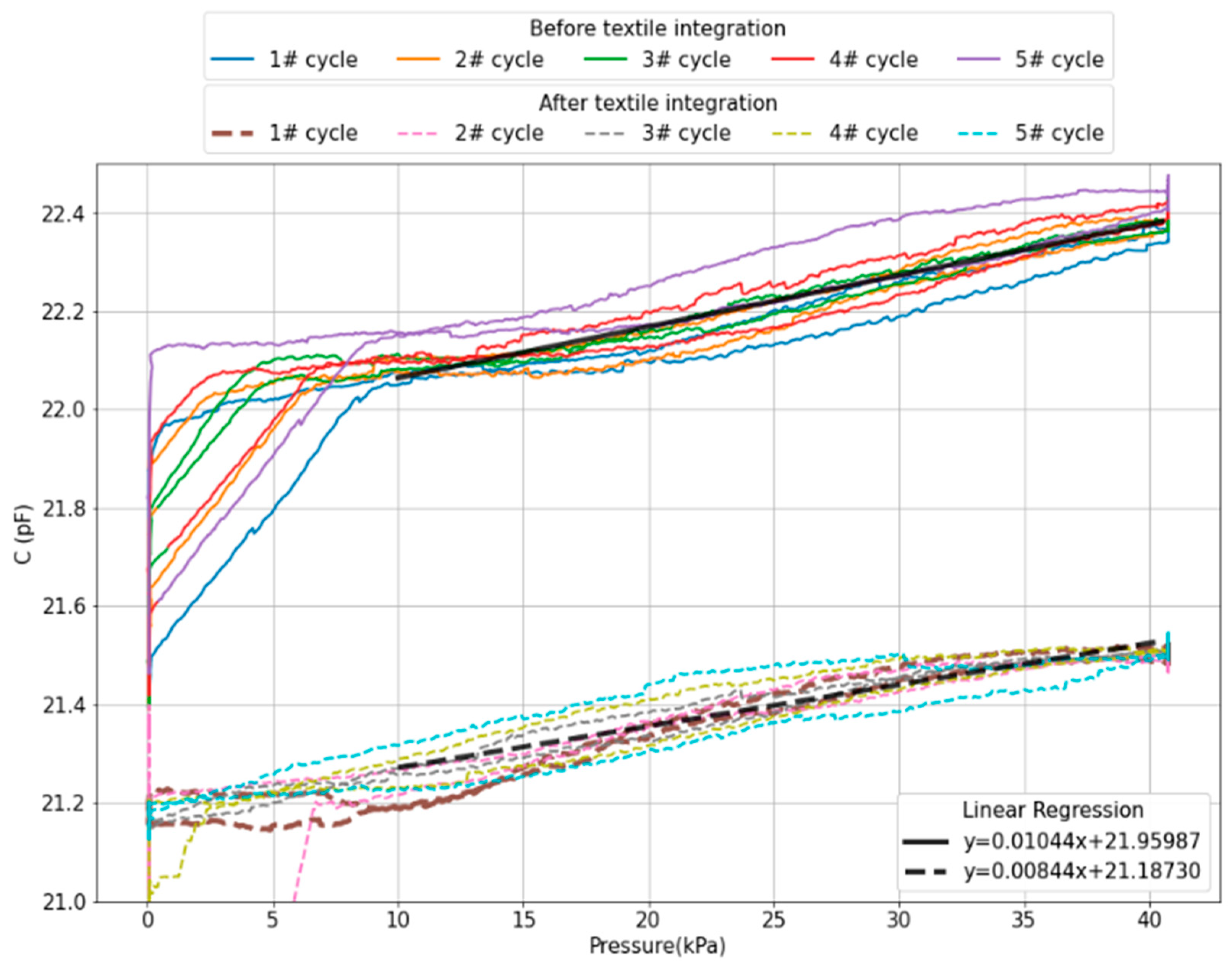
| This work | interelectrode spacing | 1 to 40 kPa | 8.44 fF/kPa | Flexible PI-based device |
Disclaimer/Publisher’s Note: The statements, opinions and data contained in all publications are solely those of the individual author(s) and contributor(s) and not of MDPI and/or the editor(s). MDPI and/or the editor(s) disclaim responsibility for any injury to people or property resulting from any ideas, methods, instructions or products referred to in the content. |
© 2024 by the authors. Licensee MDPI, Basel, Switzerland. This article is an open access article distributed under the terms and conditions of the Creative Commons Attribution (CC BY) license (https://creativecommons.org/licenses/by/4.0/).
Share and Cite
dos Santos, D.E.; Queiroz, J.B.; Garcia, I.S.; Vieira, J.; Fernandes, J.; Sotgiu, E.; Minas, G.; Bouçanova, M.; Arruda, L.M.; Fangueiro, R.; et al. Flexible Pressure and Temperature Microsensors for Textile-Integrated Wearables. Actuators 2024, 13, 42. https://doi.org/10.3390/act13010042
dos Santos DE, Queiroz JB, Garcia IS, Vieira J, Fernandes J, Sotgiu E, Minas G, Bouçanova M, Arruda LM, Fangueiro R, et al. Flexible Pressure and Temperature Microsensors for Textile-Integrated Wearables. Actuators. 2024; 13(1):42. https://doi.org/10.3390/act13010042
Chicago/Turabian Styledos Santos, Dimitri Emmanuel, José Bento Queiroz, Inês Sofia Garcia, João Vieira, José Fernandes, Edoardo Sotgiu, Graça Minas, Maria Bouçanova, Luisa Mendes Arruda, Raul Fangueiro, and et al. 2024. "Flexible Pressure and Temperature Microsensors for Textile-Integrated Wearables" Actuators 13, no. 1: 42. https://doi.org/10.3390/act13010042
APA Styledos Santos, D. E., Queiroz, J. B., Garcia, I. S., Vieira, J., Fernandes, J., Sotgiu, E., Minas, G., Bouçanova, M., Arruda, L. M., Fangueiro, R., Salgueiro-Oliveira, A., Ainla, A., Serra Alves, F., & Alves Dias, R. (2024). Flexible Pressure and Temperature Microsensors for Textile-Integrated Wearables. Actuators, 13(1), 42. https://doi.org/10.3390/act13010042