
Investigation of Pressure Chambers for Integrated Fluidic Actuators in Adaptive Slabs †

 , , and
Abstract
1. Introduction
1.1. Motivation
1.2. Previous Work
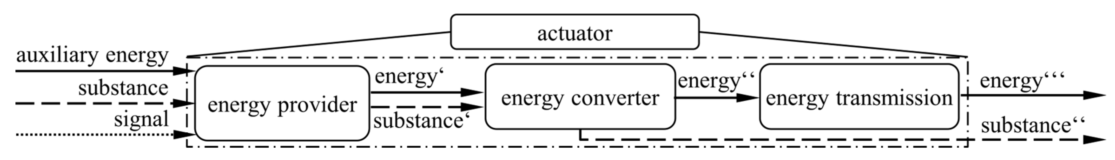
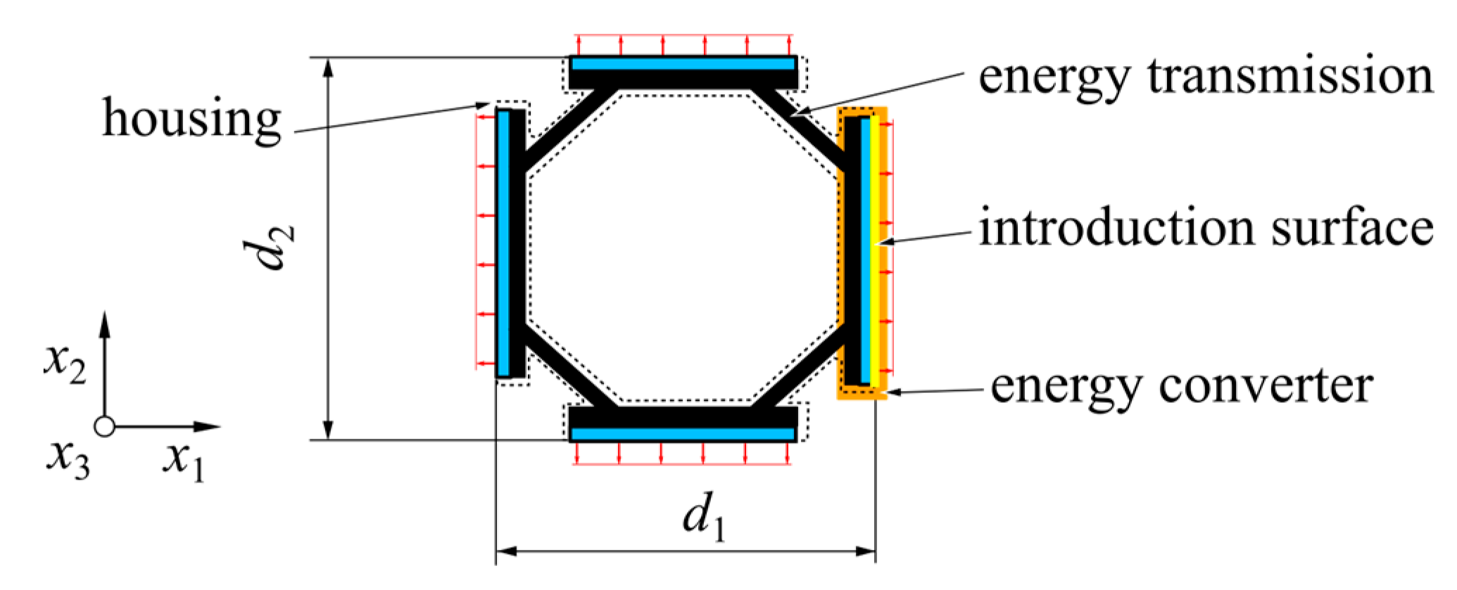
- Energy provider, which provides non-mechanical energy in a controlled manner,
- Energy converter, which converts the non-mechanical energy into mechanical energy,
- Energy transmission, where energy is transferred to the desired location and applied to the surrounding system.
1.3. Main Contribution
- 1.
- Design and first physical setup of energy converters based on the identified requirements for adaptive slabs.
- 2.
- Validation of simplified numerical models for use in designing actuator concepts in the early design phase to estimate the behavior of the energy converter for different construction sizes.
- 3.
- Experimental validation of the performance of the energy converters to meet the identified requirements.
- The identification of two requirements, forces and stroke, within a specific construction space is deepened.
- The design discussion has been expanded, and new variants for future investigation have been proposed.
- The study of different modeling approaches for 2D, 3D, and material modeling has been added.
- The sensitivity of different parameters on the numerical models compared to the experimental results has been evaluated. In particular, a study of the influence of rotational deviations with a 3D-modelled simulation model has been added.
1.4. Structure of the Paper
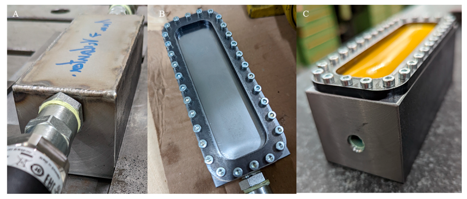
2. Prototype Design
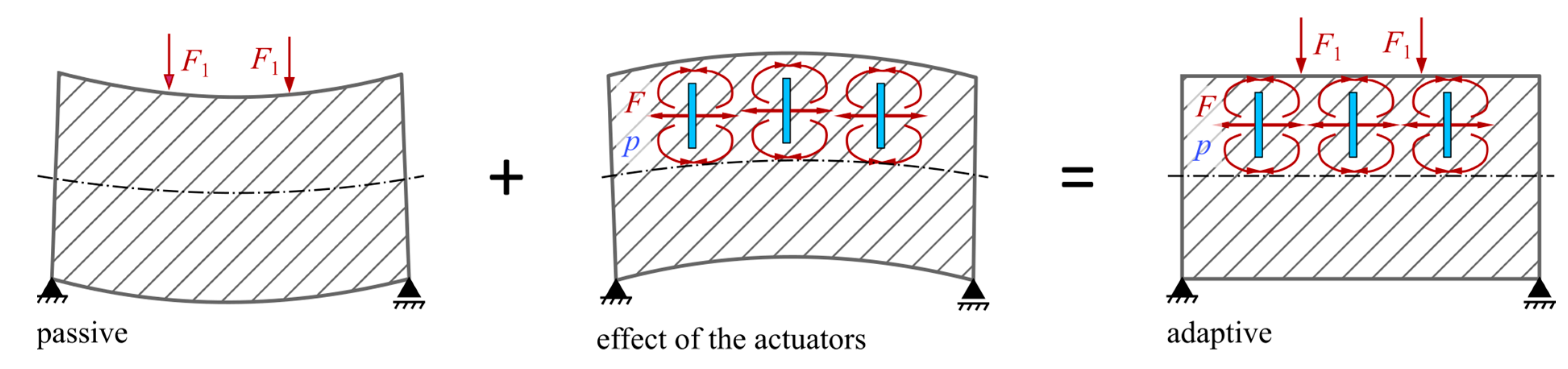
2.1. Basic Concepts for Integrated Actuators for Slabs
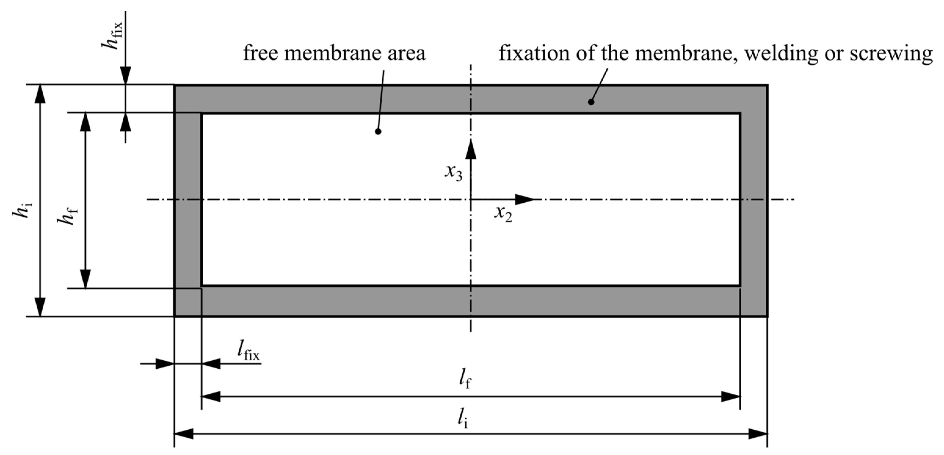
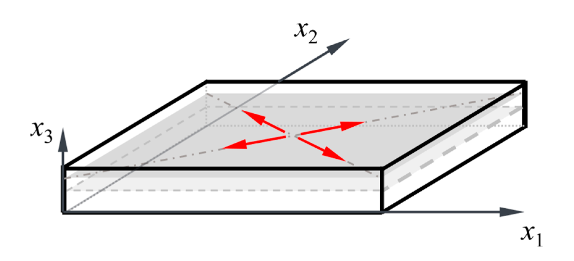
2.2. Requirements for Actuator Energy Converters for Adaptive Slabs
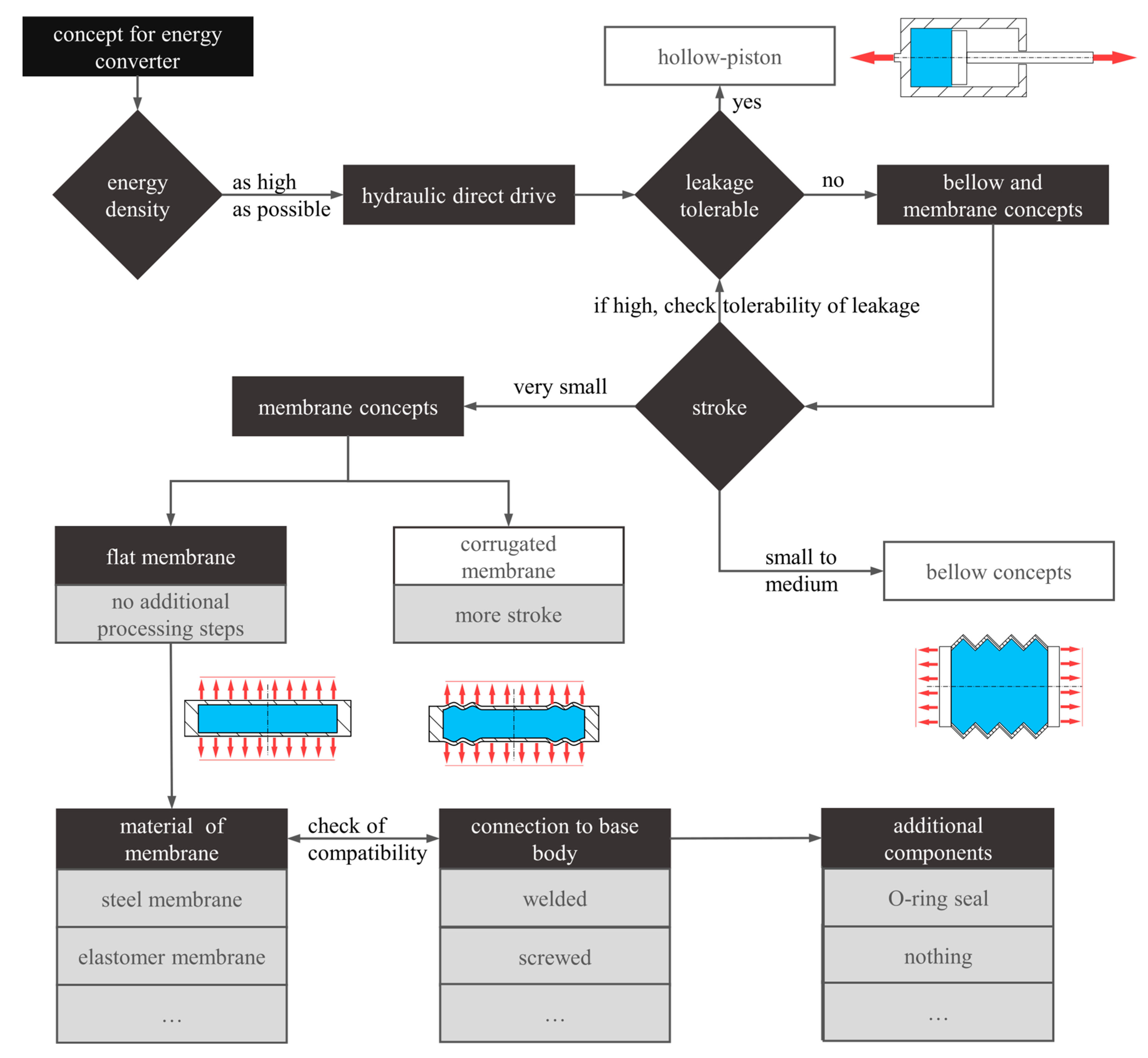
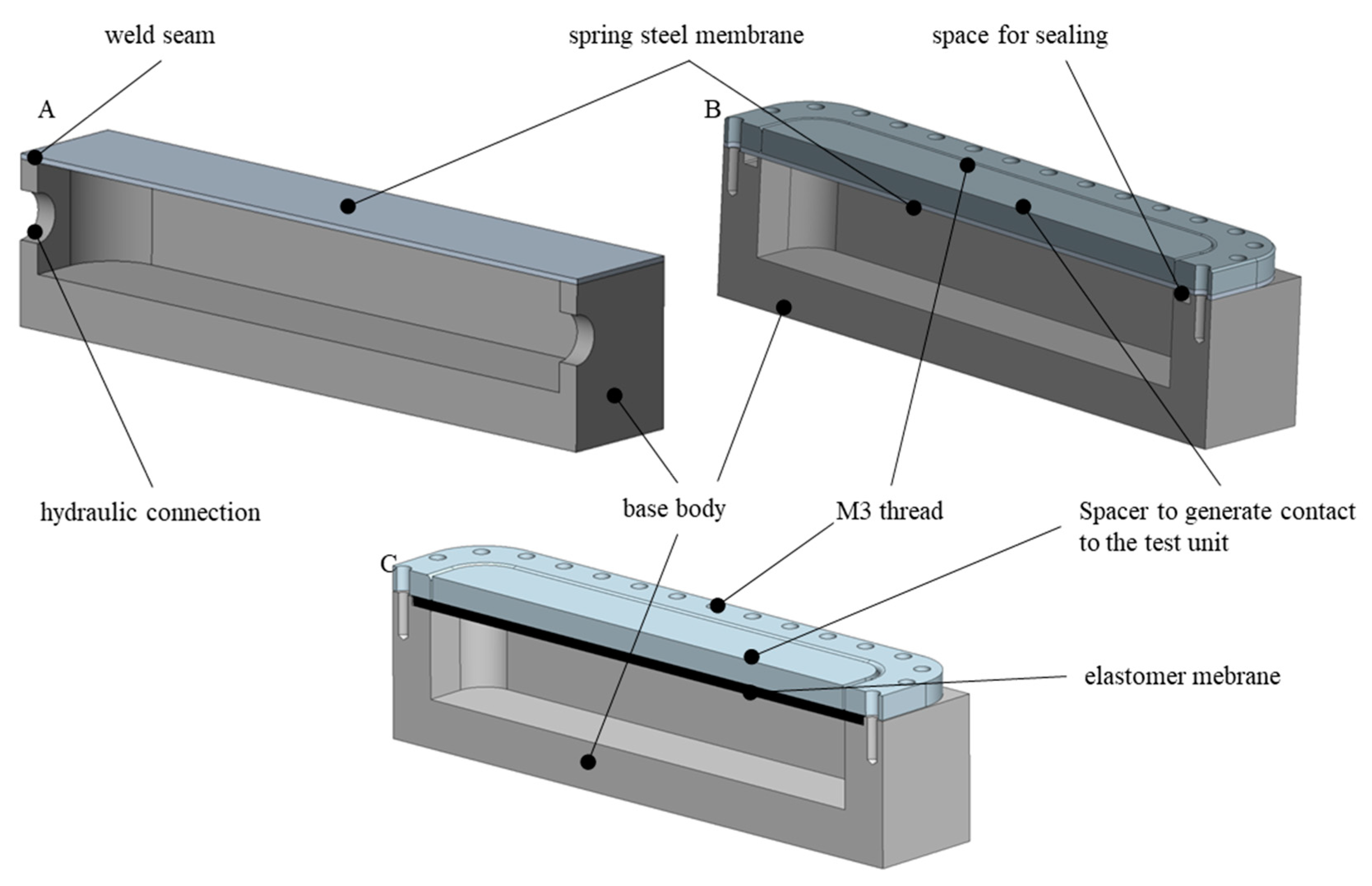
2.3. Defining Energy Converter Concepts
- Spring steel X10CrNi18-8: high strength, approx. 12% reduced Young’s modulus compared to standard steel.
- Polyurethane (PUR) D44 90° Shore A elastomer: highly resistant to abrasion and hydraulic oil, commonly used for sealing.
3. Test Setup and Numerical Models
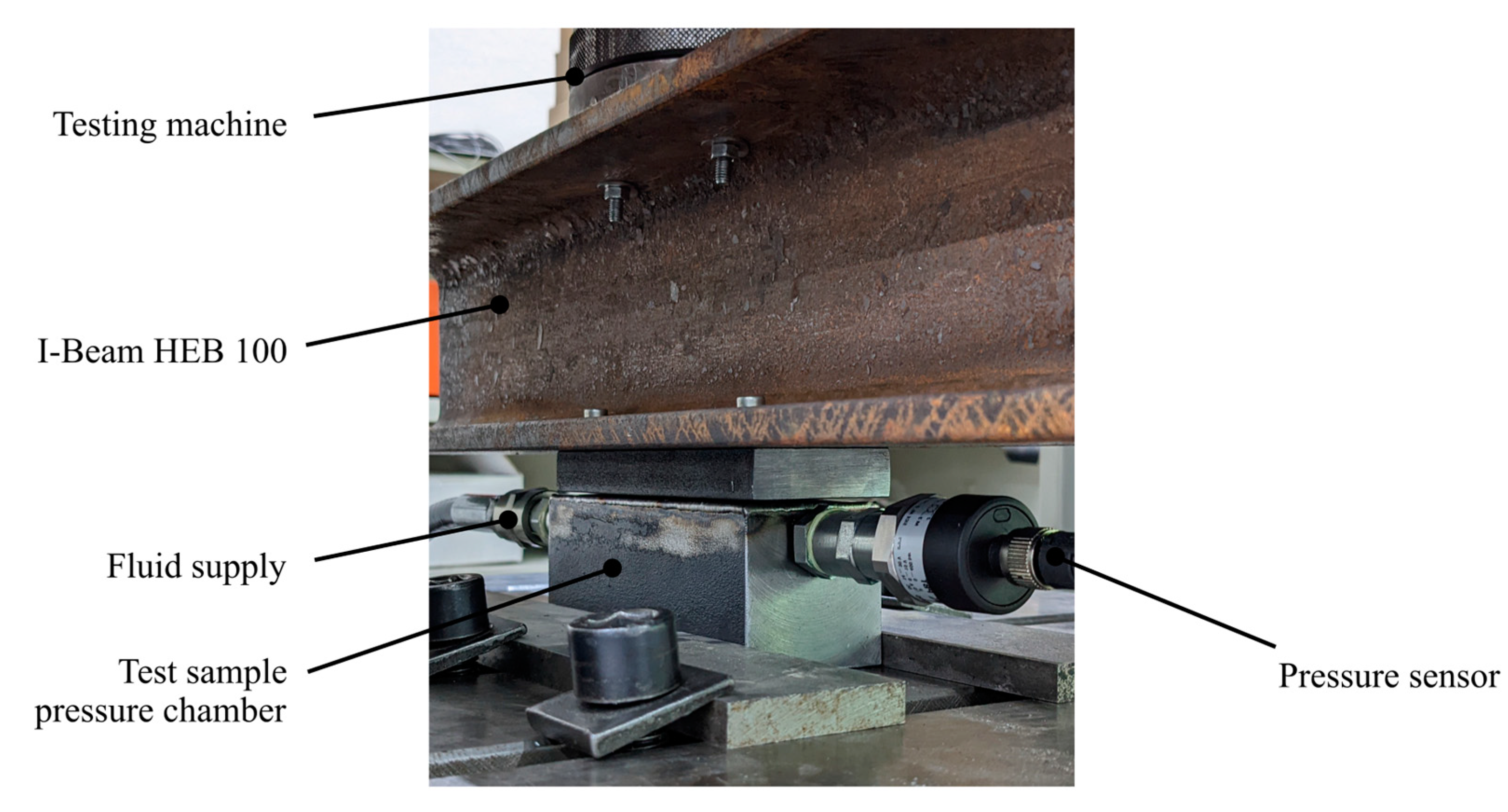
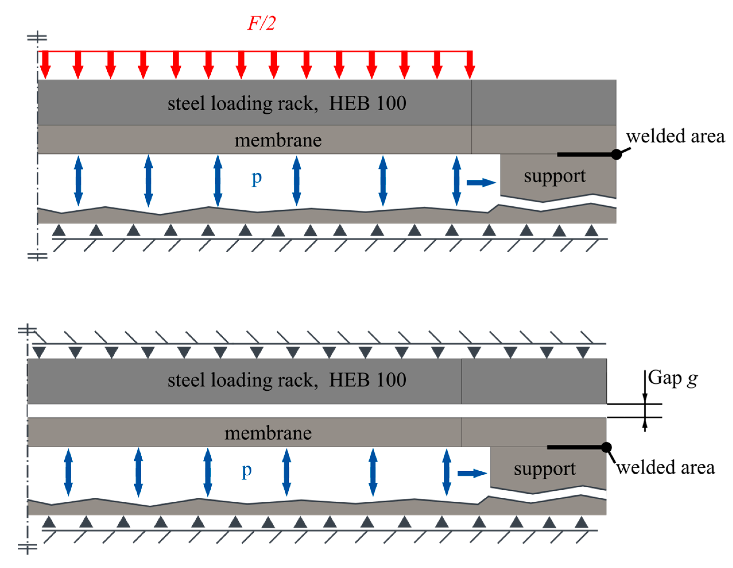
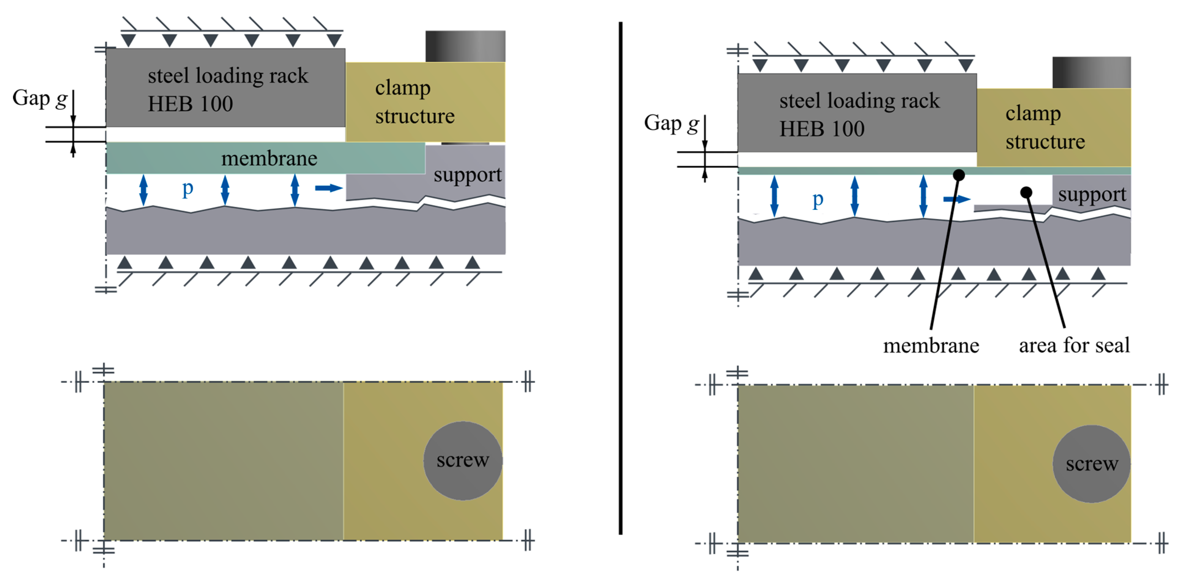
3.1. Test Setup, Test Scenarios, and Evaluation Parameters
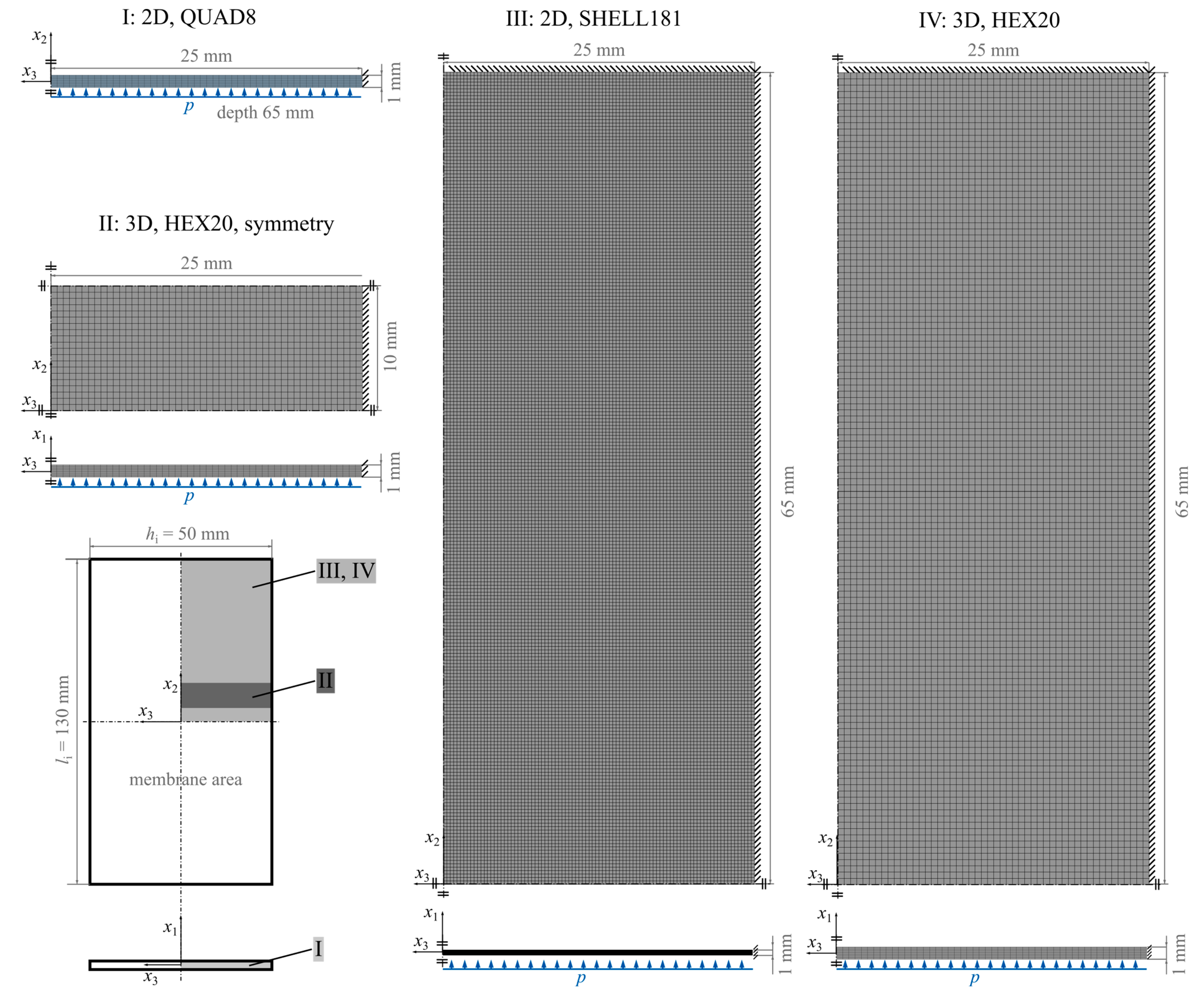
3.2. Finite Element Models for the Different Prototypes
4. Results
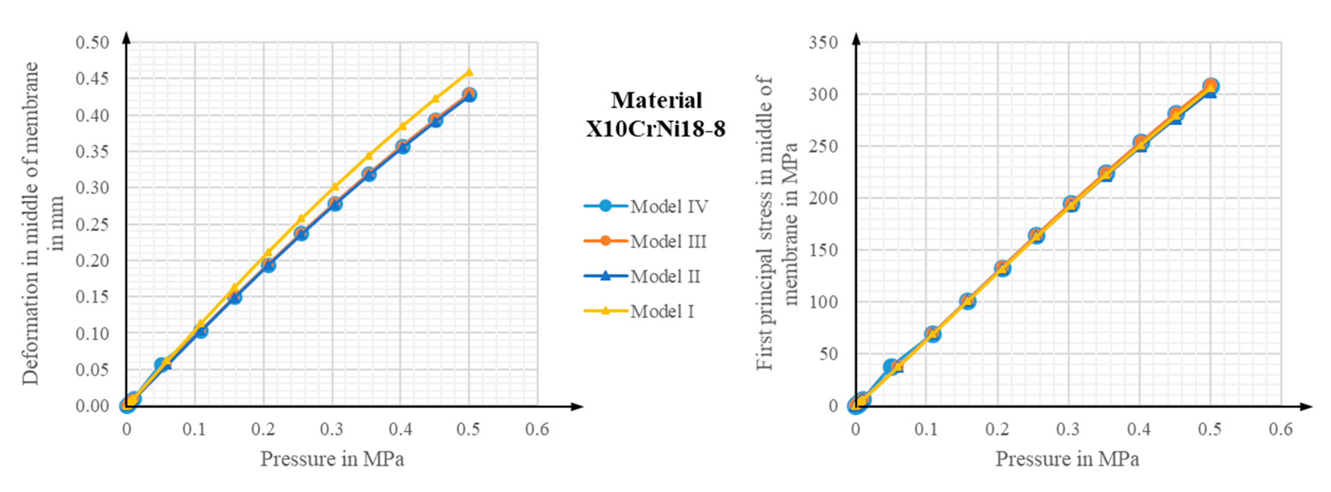
4.1. Comparison of Two- and Three-Dimensional Finite Element Basic Models
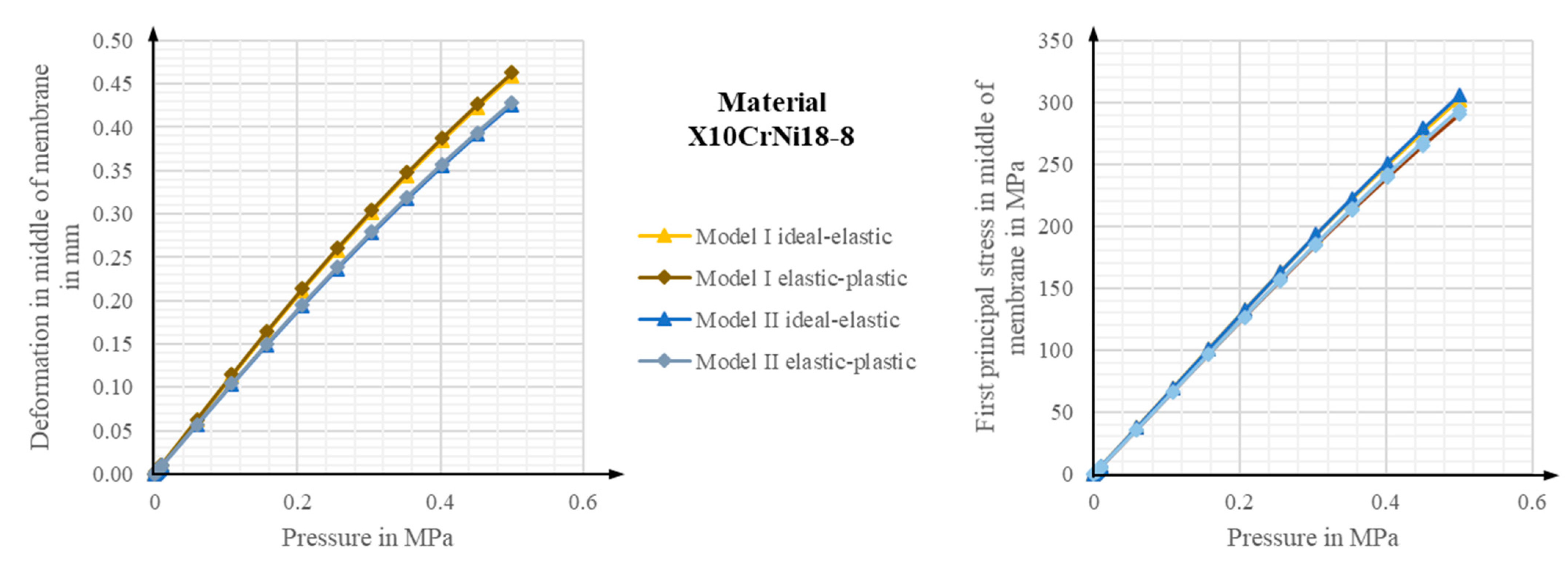
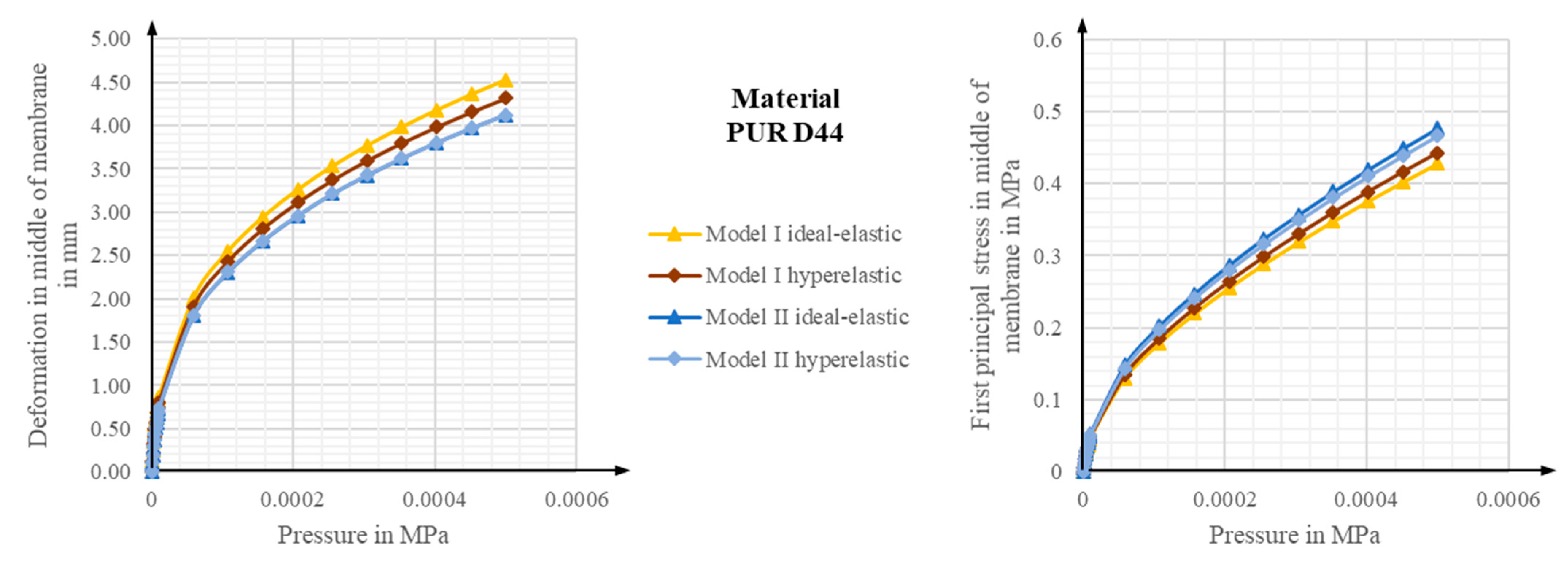
4.2. Comparison of Elastic, Elastic-Plastic, and Hyperelastic Models
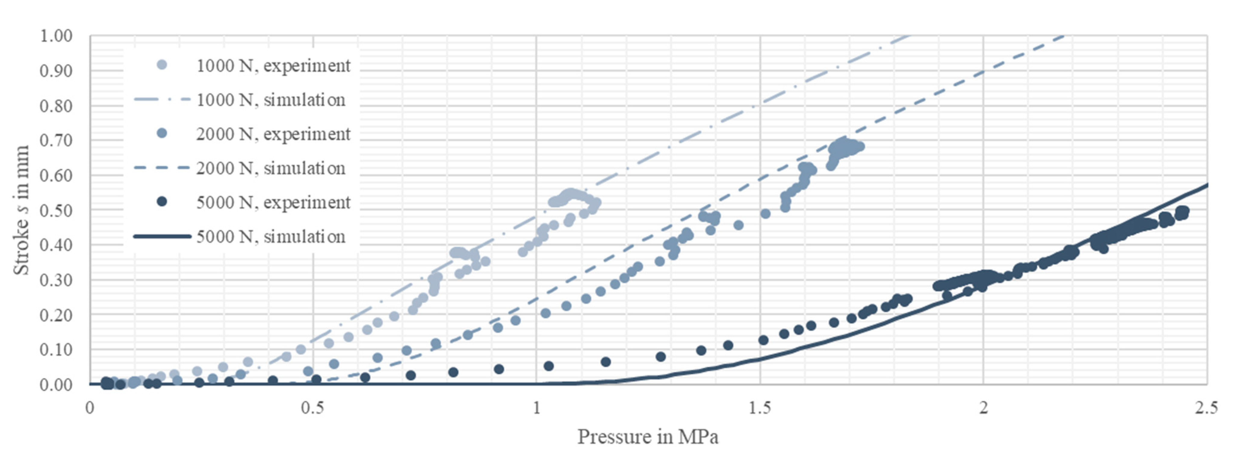
4.3. Model Tuning with Scenario One
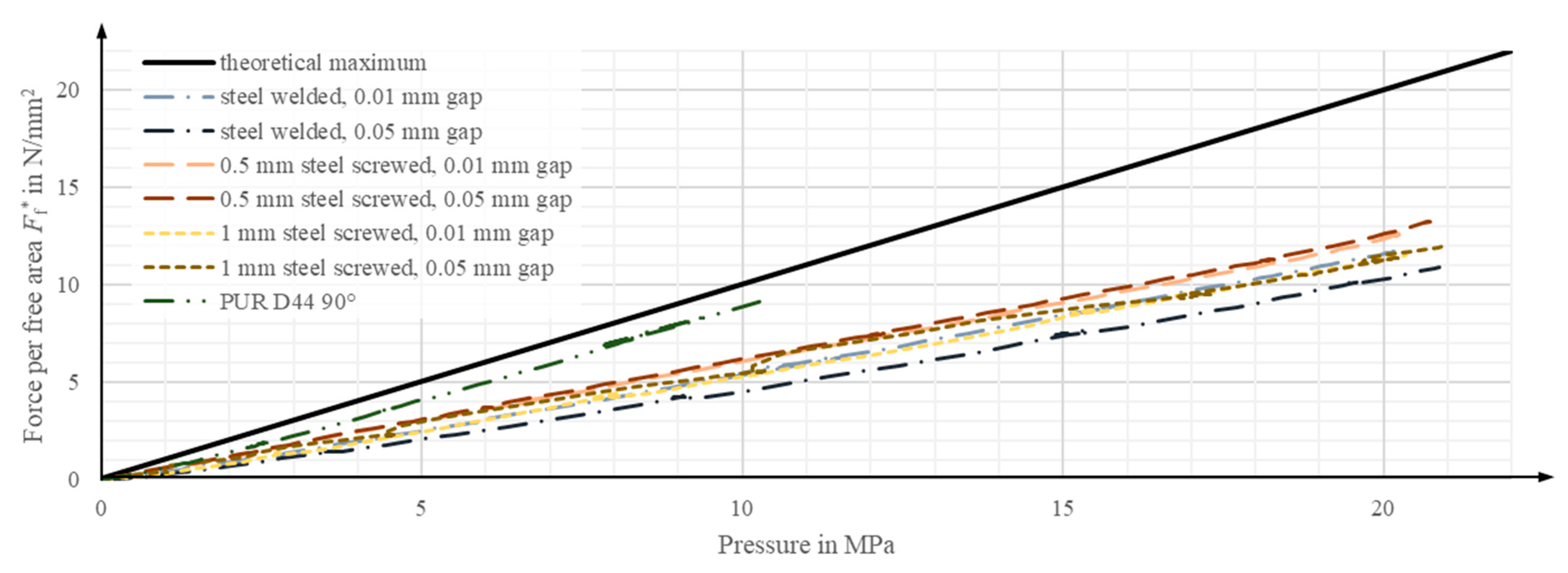
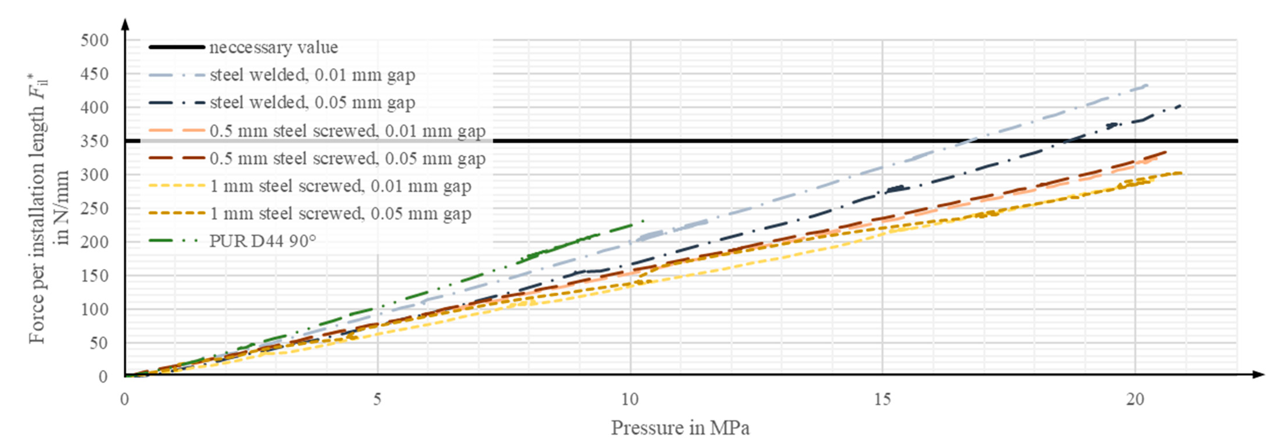
4.4. Experimental Results for Scenario Two
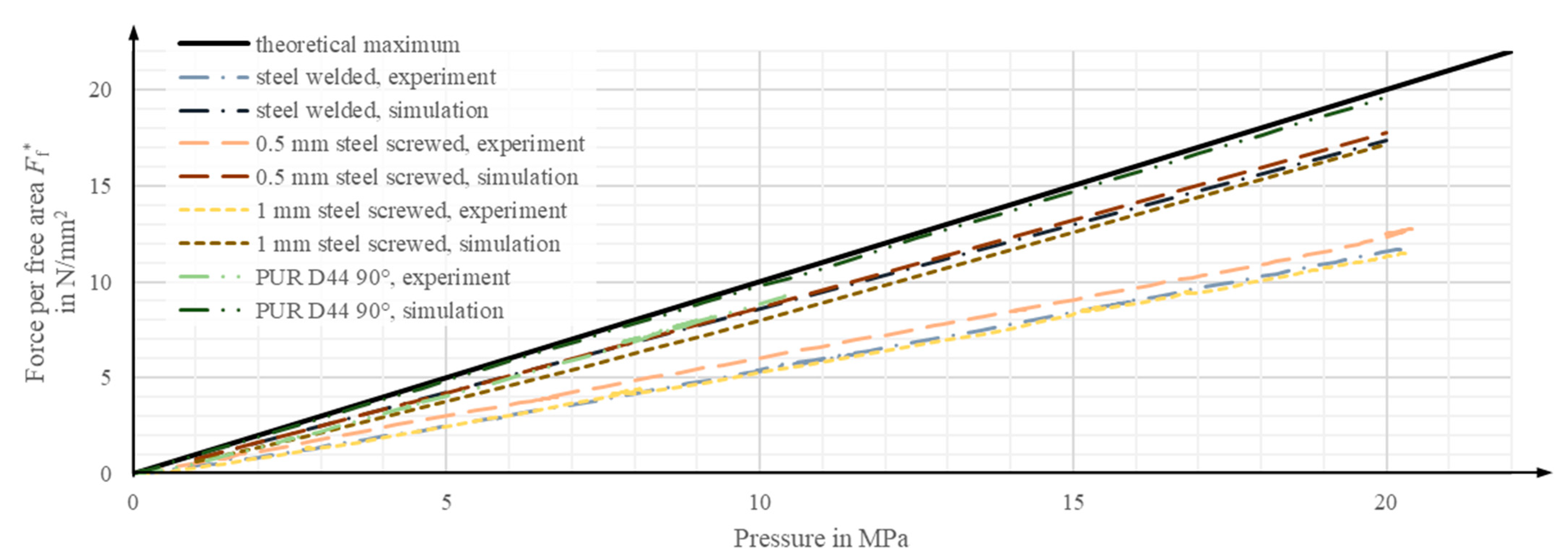
4.5. Comparison of Numerical and Experimental Results
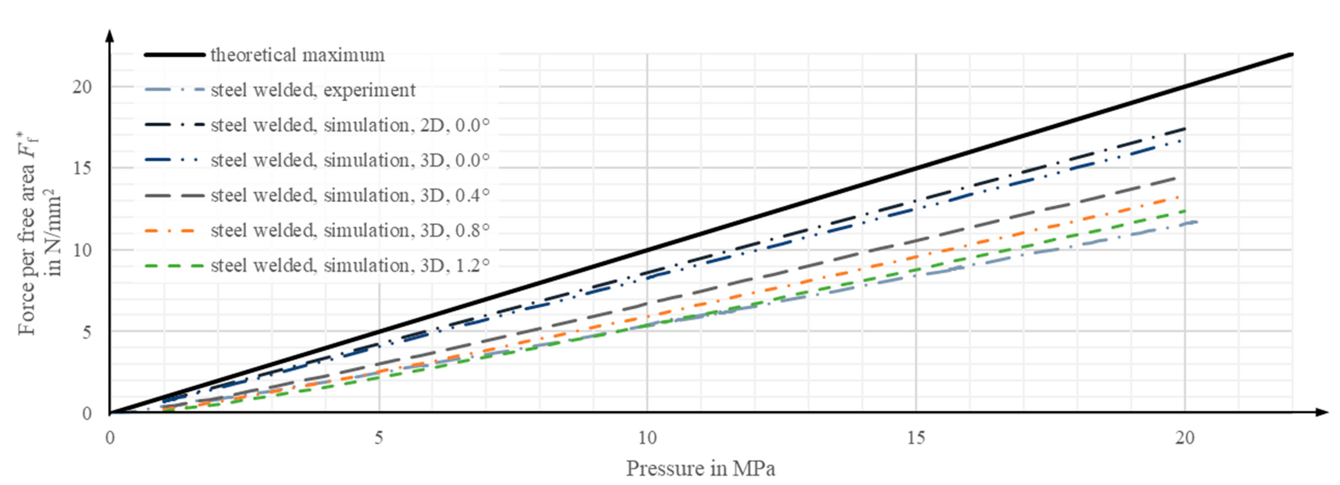
4.6. Influence of Slight Rotational Deviations on the Experiment Results
5. Discussion
6. Conclusions
Author Contributions
Funding
Data Availability Statement
Conflicts of Interest
References
- UNEP. Status Report for Buildings and Construction: Towards a Zero-Emission, Efficient and Resilient Buildings and Construction Sector; UNEP: Nairobi, Kenya, 2020. [Google Scholar]
- Sobek, W. Ultra-lightweight construction. Int. J. Space Struct. 2016, 31, 74–80. [Google Scholar] [CrossRef]
- Wang, Y.; Senatore, G. Design of adaptive structures through energy minimization: Extension to tensegrity. Struct. Multidiscipl. Optim. 2021, 64, 1079–1110. [Google Scholar] [CrossRef] [PubMed]
- Ostertag, A.; Dazer, M.; Bertsche, B.; Schlegl, F.; Albrecht, S.; Leistner, P.; Gienger, A.; Wagner, J.; Tarín, C.; Sawodny, O. Reliable Design of Adaptive Load-Bearing Structures with Focus on Sustainability. In Proceedings of the 30th European Safety and Reliability Conference and 15th Probabilistic Safety Assessment and Management Conference, (ESREL), Venice, Italy, 1–5 November 2020; Baraldi, P., Di Maio, F., Zio, E., Eds.; Research Publishing Services: Singapore, 2020; pp. 4703–4710, ISBN 978-981-14-8593-0. [Google Scholar] [CrossRef]
- Burghardt, T.; Kelleter, C.; Bosch, M.; Nitzlader, M.; Bachmann, M.; Binz, H.; Blandini, L.; Sobek, W. Investigation of a large-scale adaptive concrete beam with integrated fluidic actuators. Civ. Eng. Des. 2022, 4, 35–42. [Google Scholar] [CrossRef]
- Nitzlader, M.; Steffen, S.; Bosch, M.J.; Binz, H.; Kreimeyer, M.; Blandini, L. Designing Actuation Concepts for Adaptive Slabs with Integrated Fluidic Actuators Using Influence Matrices. CivilEng 2022, 3, 809–830. [Google Scholar] [CrossRef]
- Berger, T.; Prasser, P.; Reinke, H.G. Einsparung von Grauer Energie bei Hochhäusern. Beton-Und Stahlbetonbau 2013, 108, 395–403. [Google Scholar] [CrossRef]
- Flatt, R.J.; Roussel, N.; Cheeseman, C.R. Concrete: An eco material that needs to be improved. J. Eur. Ceram. Soc. 2012, 32, 2787–2798. [Google Scholar] [CrossRef]
- Janocha, H. Actuators: Basics and Applications; with 47 Tables; Springer: Berlin/Heidelberg, Germany, 2004; ISBN 978-3-642-08266-5. [Google Scholar] [CrossRef]
- Isermann, R. Mechatronische Systeme: Grundlagen, 2. Neu Bearb. Aufl. 2008; Springer: Berlin/Heidelberg, Germany, 2008; ISBN 978-3-540-32512-3. [Google Scholar]
- Czichos, H. Mechatronik; Springer Fachmedien Wiesbaden: Wiesbaden, Germany, 2019; ISBN 978-3-658-26293-8. [Google Scholar] [CrossRef]
- Soong, T.T.; Manolis, G.D. Active Structures. J. Struct. Eng. 1987, 113, 2290–2302. [Google Scholar] [CrossRef]
- Blandini, L.; Haase, W.; Weidner, S.; Böhm, M.; Burghardt, T.; Roth, D.J.; Sawodny, O.; Sobek, W. D1244: Design and construction of the first adaptive high-rise experimental building. Front. Built Environ. 2022, 8, 814911. [Google Scholar] [CrossRef]
- Schnellenbach-Held, M.; Fakhouri, A.; Steiner, D.; Kühn, O. Adaptive Spannbetonstruktur Mit lernfähigem Fuzzy-Regelungssystem; Carl Schünemann Verlag: Bremen, Germany, 2014; ISBN 978-3-95606-084-7. [Google Scholar]
- Neuhaeuser, S.; Weickgenannt, M.; Witte, C.; Haase, W.; Sawodny, O.; Sobek, W. Stuttgart smartshell—A full scale prototype of an adaptive shell structure. J. Int. Assoc. Shell Spat. Struct. 2013, 54, 259–270. [Google Scholar]
- Steffen, S.; Nitzlader, M.; Burghardt, T.; Binz, H.; Blandini, L.; Sobek, W. An Actuator Concept for Adaptive Concrete Columns. Actuators 2021, 10, 273. [Google Scholar] [CrossRef]
- Senatore, G.; Duffour, P.; Winslow, P. Synthesis of minimum energy adaptive structures. Struct. Multidisc. Optim. 2019, 60, 849–877. [Google Scholar] [CrossRef]
- Reksowardojo, A.P.; Senatore, G. Design of ultra-lightweight and energy-efficient civil structures through shape morphing. Comput. Struct. 2023, 289, 107149. [Google Scholar] [CrossRef]
- Senatore, G.; Duffour, P.; Winslow, P.; Wise, C. Shape control and whole-life energy assessment of an ‘infinitely stiff’ prototype adaptive structure. Smart Mater. Struct. 2018, 27, 15022. [Google Scholar] [CrossRef]
- Reksowardojo, A.P.; Senatore, G.; Srivastava, A.; Carroll, C.; Smith, I.F. Design and testing of a low-energy and -carbon prototype structure that adapts to loading through shape morphing. Int. J. Solids Struct. 2022, 252, 111629. [Google Scholar] [CrossRef]
- Soong, T.T.; Masri, S.F.; Housner, G.W. An Overview of Active Structural Control under Seismic Loads. Earthq. Spectra 1991, 7, 483–505. [Google Scholar] [CrossRef]
- Abdel-Rohman, M.; Leipholz, H.H. Active Control of Tall Buildings. J. Struct. Eng. 1983, 109, 628–645. [Google Scholar] [CrossRef]
- Reinhorn, A.M.; Soong, T.T.; Lin, R.C.; Riley, M.A.; Wang, Y.P.; Aizawa, S.; Higashino, M. Active Bracing System: A Full Scale Implementation of Active Control, Technical Report NCEER-92-0020, 1992; National Center for Earthquake Engineering Research, University at Buffalo: New York, NY, USA, 1992. [Google Scholar] [CrossRef]
- Bani-Hani, K.; Ghaboussi, J. Nonlinear Structural Control Using Neural Networks. J. Eng. Mech. 1998, 124, 319–327. [Google Scholar] [CrossRef]
- Connor, J.J. Introduction to Structural Motion Control; Prentice Hall: Upper Saddle River, NJ, USA, 2003; ISBN 0130091383. [Google Scholar]
- Heidenreich, C. Adaptivität von Freigeformten Flächentragwerken-Möglichkeiten zur Steigerung der Effizienz von Faserverbundstrukturen im Bauwesen. Ph.D. Thesis, Bauhaus-Universität Weimar, Weimar, Germany, 2016. [Google Scholar] [CrossRef]
- Trautwein, A.; Prokosch, T.; Bischoff, M. A case study on tailoring stiffness for the design of adaptive rib-stiffened slabs. In Towards White-Box Modeling of Sensory-Utilized Rolling Bearings, Proceedings of the 10th ECCOMAS Thematic Conference on Smart Structures and Materials, Patras, Greece, 7 March–7 May 2023; Puchtler, S., van der Kuip, J., Kirchner, E., Eds.; Departmet of Mechanical Engineering & Aeronautics, University of Patras: Patras, Greece, 2023; pp. 671–678. ISBN 978-960-88104-6-4. [Google Scholar] [CrossRef]
- Korvink, J.-G.; Schlaich, M. Autonome Brücken-ein Blick in die ferne Zukunft des Brückenbaus. Bauingenieur 2000, 75, 29–34. [Google Scholar]
- Bossens, F.; Preumont, A. Active tendon control of cable-stayed bridges: A large-scale demonstration. Earthq. Eng. Struct. Dyn. 2001, 30, 961–979. [Google Scholar] [CrossRef]
- Weilandt, A. Adaptivität bei Flächentragwerken. Ph.D. Thesis, Universität Stuttgart, Stuttgart, Germany, 2008. [Google Scholar] [CrossRef]
- Marker, P.; Bleicher, A. A Hierarchical Optimization Method for the Design of Active Hybrid Structures. Front. Built Environ. 2022, 8, 705434. [Google Scholar] [CrossRef]
- Kelleter, C. Untersuchungen Zur Manipulation Des Lastabtrages Biegebeanspruchter Betonbauteile Durch Integrierte Fluidische Aktoren. Ph.D. Thesis, Universität Stuttgart, Stuttgart, Germany, 2022. [Google Scholar] [CrossRef]
- Bosch, M.J.; Nitzlader, M.; Bachmann, M.; Binz, H.; Blandini, L.; Kreimeyer, M. Experimental Testing of Actuator Chambers of Integrated Fluidic Actuators for Adaptive Slabs. In Proceedings of the ICEM20, Experimental Mechanics in Engineering and Biomechanics, Porto, Portugal, 2–7 June 2023; Silva Gomes, J.F., Ed.; INEG: Porto, Portugal, 2023. ISBN 978-989-54756-7-4. [Google Scholar]
- Bosch, M.; Nitzlader, M.; Burghardt, T.; Bachmann, M.; Binz, H.; Blandini, L.; Kreimeyer, M. Design of integrated fluidic actuators for muti-axial loaded structural elements. In Proceedings of the 8th European Congress on Computational Methods in Applied Sciences and Engineering, CIMNE, Oslo, Norway, 5–9 June 2022. [Google Scholar] [CrossRef]
- DIN Deutsches Institut für Normung e., V. DIN EN 206, Concrete-Specification, Performance, Production and Conformity, German Version EN 206:2013+A2:2021; Beuth Verlag GmbH: Berlin, Germany, 2021. [Google Scholar]
- Weidner, S.; Kelleter, C.; Sternberg, P.; Haase, W.; Geiger, F.; Burghardt, T.; Honold, C.; Wagner, J.; Böhm, M.; Bischoff, M.; et al. The implementation of adaptive elements into an experimental high-rise building. Steel Constr. 2018, 11, 109–117. [Google Scholar] [CrossRef]
- Di Giovanni, M. Flat and Corrugate Diaphragm Design Handbook; Dekker: New York, NY, USA, 1982; ISBN 0824712811. [Google Scholar]
- Ramberg, W.; Osgood, W.R. Description of Stress-Strain Curves by Three Parameters NACA-TN-902. 1943. Available online: https://ntrs.nasa.gov/citations/19930081614 (accessed on 7 December 2023).
- Li, T.; Zheng, J.; Chen, Z. Description of full-range strain hardening behavior of steels. Springerplus 2016, 5, 1316. [Google Scholar] [CrossRef] [PubMed]
- Falter, J.; Binz, H.; Kreimeyer, M. Investigations on design limits and improved material utilization of press-fit connections using elastic-plastic design. Appl. Eng. Sci. 2023, 13, 100124. [Google Scholar] [CrossRef]
- Junik, K.; Lesiuk, G.; Duda, S.; Jamroziak, K.; Błażejewski, W.; Zielonka, P.; Socha, T.; Denisiewicz, A.; Kula, K.; Szczurek, A. Constitutive Law Identification and Fatigue Characterization of Rigid PUR Elastomers 80 ShA and 90 ShA. Materials 2022, 15, 6745. [Google Scholar] [CrossRef] [PubMed]


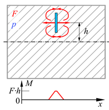
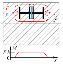
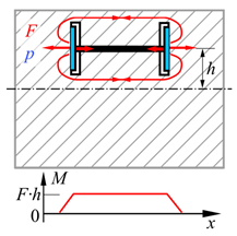
| Location Energy Converter | Central | Decentral | |
|---|---|---|---|
| Effective Range | Local | Semi-Local | |
| Concept Class | CC1 | CC2 | CC3 |
 |  |  | |
| Description | Symbol | Quantity | Unit |
|---|---|---|---|
| Max. stroke in concrete related to force and spatial extension | s/(F/l) | 0.0000222 | mm2/N |
| Max. actuating force per spatial direction related to the spatial extension of the actuator | F/l | 350 | N/mm |
| Installation height | hi | 45–50 | mm |
| Installation length | li = d2 | 130 | mm |
| Serviceability | - | Not possible | - |
| Leakage | - | No leakage | - |
| Max. pressure at contact | pmax | 0.45 fck | N/mm2 |
| Edge condition | - | Rounded | - |
| Screwing | Welding | |
|---|---|---|
| Pros |
|
|
| Cons |
|
|
| Variant 1 | Variant 2 | Variant 3 |
|---|---|---|
 | 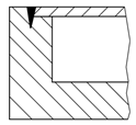 |  |
| Heat-conducting seam | Deep weld seam from top | Deep weld seam from the side |
| + Easy manufacturing + No laser welding necessary + No sensitivity to dimensional deviations | + Easy manufacturing + High bond strength | + Tensile stress at the weld seam + Area of bending does not coincide with weld seam + High bond strength |
| o Load condition is unclear | o Small sensitivity to dimensional deviations | |
| − Low bond strength − Area of high bending stress coincides with weld seam | − Laser welding necessary − Area of high bending stress coincides with weld seam | − Additional manufacturing step − Laser welding necessary − High sensitivity to dimensional deviations |
| Scenario 1 | Scenario 2 | |
|---|---|---|
| Constant parameter | force | path |
| Initial condition | defined applied force | defined gap between membrane and loading rig |
| Force range | 1000–5000 N | - |
| Gap range | - | 0–0.05 mm |
| Pressure limit | 2.5 MPa | 20 MPa |
| Evaluation parameter | stroke | force |
| Tested variants | A | A, B, C |
| Description | Symbol | Unit | Spring Steel, X10CrNi18-8 | Structural Steel, S 235 | PUR-Elastomer D44 90° Shore A |
|---|---|---|---|---|---|
| Young’s modulus | E | N/mm2 | 185,000 | 210,000 | 15 (calculated) |
| Poisson’s ratio | ν | - | 0.3 | 0.3 | 0.48 |
| Description | I | II | III | IV |
|---|---|---|---|---|
| Element type | QUAD8 | HEX20 | SHELL181 | HEX20 |
| Number of nodes | 821 | 45,261 | 22,320 | 285,281 |
| Number of elements | 250 | 10,000 | 21,988 | 65,000 |
| Description | Welded, 2D | Welded, 3D | Screwed, 3D Metal | Screwed, 3D Elastomer |
|---|---|---|---|---|
| Nodes | 214,516 | 350,010 | 527,991 | 527,991 |
| Elements | 70,096 | 179,637 | 274,176 | 274,176 |
Disclaimer/Publisher’s Note: The statements, opinions and data contained in all publications are solely those of the individual author(s) and contributor(s) and not of MDPI and/or the editor(s). MDPI and/or the editor(s) disclaim responsibility for any injury to people or property resulting from any ideas, methods, instructions or products referred to in the content. |
© 2024 by the authors. Licensee MDPI, Basel, Switzerland. This article is an open access article distributed under the terms and conditions of the Creative Commons Attribution (CC BY) license (https://creativecommons.org/licenses/by/4.0/).
Share and Cite
Bosch, M.J.; Nitzlader, M.; Bachmann, M.; Binz, H.; Blandini, L.; Kreimeyer, M. Investigation of Pressure Chambers for Integrated Fluidic Actuators in Adaptive Slabs. Actuators 2024, 13, 41. https://doi.org/10.3390/act13010041
Bosch MJ, Nitzlader M, Bachmann M, Binz H, Blandini L, Kreimeyer M. Investigation of Pressure Chambers for Integrated Fluidic Actuators in Adaptive Slabs. Actuators. 2024; 13(1):41. https://doi.org/10.3390/act13010041
Chicago/Turabian StyleBosch, Matthias J., Markus Nitzlader, Matthias Bachmann, Hansgeorg Binz, Lucio Blandini, and Matthias Kreimeyer. 2024. "Investigation of Pressure Chambers for Integrated Fluidic Actuators in Adaptive Slabs" Actuators 13, no. 1: 41. https://doi.org/10.3390/act13010041
APA StyleBosch, M. J., Nitzlader, M., Bachmann, M., Binz, H., Blandini, L., & Kreimeyer, M. (2024). Investigation of Pressure Chambers for Integrated Fluidic Actuators in Adaptive Slabs. Actuators, 13(1), 41. https://doi.org/10.3390/act13010041