Article

Dynamic Response Analysis of a Magnetically Suspended Dual-Rotor System Considering the Uncertainty of Interference-Fit Value

1
School of Machinery and Automation, Wuhan University of Science and Technology, Wuhan 430081, China
2
Hubei Key Laboratory of Mechanical Transmission and Manufacturing Engineering, Wuhan University of Science and Technology, No. 947, Heping Venue, Qingshan District, CT, Wuhan 430081, China
*
Author to whom correspondence should be addressed.
Actuators 2024, 13(1), 33; https://doi.org/10.3390/act13010033
Submission received: 25 November 2023 / Revised: 8 January 2024 / Accepted: 11 January 2024 / Published: 14 January 2024
(This article belongs to the Section Miniaturized and Micro Actuators)

Abstract

:
Interference fit is often used in rotating machinery to transmit torque and force. The actual interference value is uncertain due to factors such as manufacturing errors and operating conditions, resulting in a gap between the response of the system and theoretical results. Therefore, the interval method is used to study the magnetically suspended dual-rotor system (MSDS) with uncertainty of interference-fit value. Firstly, a theoretical model of the MSDS was established using the finite element method, and the influence mechanism of the interference value on the rotor bending stiffness was derived. Then, the rotor stiffness range was obtained from the uncertain range of interference value. Finally, the dynamic response of the MSDS was studied based on the Chebyshev interval method. The research results indicate that the uncertainty of interference value has an effect on the vibration response of the MSDS. The vibration response of the system is most affected near the first-order bending critical speed, and the effect on rotor response is relatively small in other angular speed regions. The research results can provide a basis for the design of rotor systems.

1. Introduction

Active magnetic bearing (AMB) is a new type of bearing that achieves stable rotor suspension by controllable electromagnetic force. It has several advantages such as no contact, no lubrication, no wear, high rotational speed, and adjustable dynamic characteristics [1]. Rotors supported by electromagnetic bearings are well-suited for extreme environments, such as high-speed and vacuum. Research focusing on the active magnetic bearing is an important development direction in the future.
Interference fit is widely used in magnetically suspended rotor systems due to its excellent characteristics such as strong load-bearing capacity, simple structure, and low-cost manufacturing. Many scholars at home and abroad have studied the characteristics of interference fit. Li et al. [2] studied the influence of interference fit between the gear and shaft on gear transmission performance in automotive transmissions. Hu et al. [3] proposed an error calculation model for shaft holes during the interference-fit stage. Liu et al. [4] studied the influence of interference fit between shaft and gear on the meshing characteristics of cylindrical gears. Suo et al. [5] conducted experimental and numerical studies on the wear damage mechanism of the interference-fit interfaces. Shu et al. [6] analyzed the distribution of wear debris, damage, and crack initiation characteristics of the axle in the interference-fit contact area. Lanoue et al. [7] studied the displacement and stress near the contact edge of the interference fit. Wang et al. [8] studied the effect of interference fit on the dynamic characteristics of the spindle rotor system. Güven [9] studied the effect of the design parameters on the root bending stress considering the interference fit between the shaft and gear. Pedersen [10] optimized the design of the shaft and hub assembled by interference fit to improve the contact-pressure distribution. Gruescu et al. [11] determined the value of interference fit by calculating the necessary contact pressure for transmitting axial and/or tangential loadings. Storti and Fonçatti [12] proposed a specific calculation routine based on ANSYS finite element analysis to study the influence of interference fit on the rotor dynamic behavior of the machine. Kovan [13] conducted stress and separation frequency analyses of interference fit between the shaft and hub. Vishwakarma et al. [14] studied the influence of tapered interference fit between the impeller and shaft in a centrifugal compressor. It is evident that interference fit has a significant impact on system characteristics.
When the shaft is in interference fit with other parts, contact pressure will be formed on the contact surface and an additional stiffness will be generated on the rotor, thereby affecting the dynamic characteristics of the rotor system. In the actual rotors, due to the influence of manufacturing errors, operating conditions, and other factors, there is uncertainty in the actual interference-fit value, making it difficult to accurately describe the dynamic characteristics of the rotor. Therefore, it is necessary to consider the impact of uncertain interference value on the dynamic characteristics of the rotor during the research process.
In the study of rotor systems, there has been some research on the quantification of uncertainty issues. Among them, the interval method [15,16,17,18] has been widely used because it does not need to know the prior probability distribution of the parameters and select the membership functions to obtain the response interval of the rotor system. Fu et al. [19,20] studied the effects of different uncertain parameters on rotor imbalance response and crack response using an interval precise integration method. Chen and Guo [21] introduced interval Gaussian kernel functions to measure interval fault diagnosis of rotor cracks under uncertain conditions. Ma et al. [22,23] proposed an interval analysis method based on Chebyshev expansion to analyze the dynamic response of rotors under uncertain parameters. Molina et al. [24] analyzed the structural response sensitivity of flexible rotors under uncertain interval parameters. Hao et al. [25] established an equation for calculating the natural frequency of a rotor system with uncertain parameters through interval Taylor expansion analysis. Barbosa et al. [26] used interval uncertainty and sensitivity methods to evaluate the influences of uncertain parameters on the dynamic behavior of the shaft. Although there have been many studies on the uncertainty issues of the rotor, there has been no study considering the influence of the uncertain interference value of the shaft components.
In response to the shortcomings in the existing research, this paper derives the influence mechanism of the interference value on the rotor stiffness and models the interference value in the magnetically suspended dual-rotor system (MSDS) as an interval value, thereby obtaining the rotor stiffness interval. Finally, the dynamic response of the MSDS with uncertain interference value is studied by the Chebyshev interval method.

2. Dual-Rotor Model and Its Motion Equation

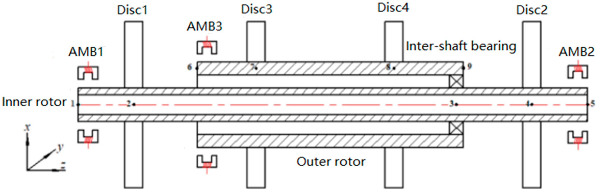
2.1. Structure of the Magnetically Suspended Dual-Rotor System

Based on the structural characteristics of the rotor components in a multi-electric aviation engine, a MSDS is designed. The main structure is shown in Figure 1. The inner rotor and outer rotor simulate the low-pressure shaft and high-pressure shaft in the aviation engine respectively, and the coupling of the inner and outer rotors is achieved through a rolling bearing as an inter-shaft bearing. Among them, discs 1 and 2 are low-pressure shaft turbine discs, while discs 3 and 4 are high-pressure shaft turbine discs. The inner rotor is supported by two active magnetic bearings, and the outer rotor is supported by one active magnetic bearing.
Table 1 displays the primary structural parameters of the MSDS. This article mainly studies the radial vibration of the rotor under high-speed conditions. The mass of the rotor is relatively small. Therefore, for the convenience of analysis, the following assumptions were taken into account: (a) Neglecting the effects of torsional and axial vibrations, only considering radial vibrations; (b) Neglecting the influence of the rotor gravity.

2.2. Dynamics Equations of the System

In the rest of the work, the term “shaft element” should be understood as a two-node finite beam element determined based on the Euler-Bernoulli beam theory. The inner rotor is discretized into 5 nodes and the outer rotor is discretized into 4 nodes.
The displacement vectors of the inner and outer rotors can be determined from Figure 1:
{ q 1 L = [ x 1 , θ y 1 , x 2 , θ y 2 , , x 5 , θ y 5 ] T q 2 L = [ y 1 , θ x 1 , y 2 , θ x 2 , , y 5 , - θ x 5 ] T q 1 H = [ x 6 , θ y 6 , x 7 , θ y 7 , , x 9 , θ y 9 ] T q 2 H = [ y 6 , θ x 6 , y 7 , θ x 7 , , y 9 , - θ x 9 ] T
where q1L and q2L represent the generalized displacement vectors of the inner rotor. q1H and q2H represent the generalized displacement vectors of the outer rotor. xk and yk (k = 1, 2,…, 5) denote the translational displacements of the inner rotor nodes 1~5 along the x and y axes, respectively. xk and yk (k = 6,…, 9) denote the translational displacements of the outer rotor nodes 6~9 along the x and y axes. θxk and θyk (k = 1, 2,…, 5) refer to the rotational displacements of the inner rotor nodes 1~5 around the x and y axes, while θxk and θyk (k = 6,…, 9) indicate the rotational displacements of the outer rotor nodes 6~9 around the x and y axes.
By assembling the motion equations of each of the shaft elements and discs of the inner and outer rotor, the motion equations of the inner and outer rotors in the XOZ and YOZ planes can be obtained as follows:
{ M L q ¨ 1 L + ω L J L q ˙ 2 L + K L q 1 L = F 1 L M L q ¨ 2 L + ω L J L q ˙ 1 L + K L q 2 L = F 2 L M H q ¨ 1 H + ω H J H q ˙ 2 H + K H q 1 H = F 1 H M H q ¨ 2 H + ω H J H q ˙ 1 H + K H q 2 H = F 2 H
where ML, JL, and KL represent the mass matrix, gyroscopic matrix, and stiffness matrix of the inner rotor. MH, JH, and KH represent the mass matrix, gyroscopic matrix, and stiffness matrix of the outer rotor. The angular speed of the inner and outer rotors are represented by ωL and ωH, and ωH = ru*ωL, where ru is the angular speed ratio between the outer rotor and the inner rotor. Furthermore, F1L and F2L are generalized forces that act on the inner rotor in the XOZ and YOZ planes, F1H and F2H are generalized forces that act on the outer rotor in the XOZ and YOZ planes. When the unbalances are located on discs 2 and 4, F1L, F2L, F1H, and F2H can be expressed as:
{ F 1 L = [ F a x , 1   0 0 0 0 0 m 2 e ω L 2 sin ( ω L t )   0 F a x , 2   0 ] T F 2 L = [ F a y , 1 0 0 0 0 0 m 2 e ω L 2 cos ( ω L t ) 0   F a y , 2   0 ] T F 1 H = [ F a x , 3 0 0 0 m 4 e ω H 2 sin ( ω H t ) 0 0 0 ] T F 2 H = [ F a y , 3   0 0 0   m 4 e ω H 2 cos ( ω H t ) 0 0 0 ] T
where Fax, k (k = 1, 2, 3) is the bearing force of the active magnetic bearing 1, 2, and 3 in the x direction. Fay, k (k = 1, 2, 3) is the bearing force of the active magnetic bearing 1, 2, and 3 in the y direction. Furthermore, m2 and m4 are the unbalanced masses of discs 2 and 4, and e is the eccentricity of discs 2 and 4.
According to the node number of the inter-shaft bearing shown in Figure 1, the system’s gyroscopic matrix and stiffness matrix are modified [27].
For the convenience of description, the motion equation of the MSDS can be simplified as:
M q ¨ + C q ˙ + K q = F

3. Interval Method Model with Uncertainty of Interference Value

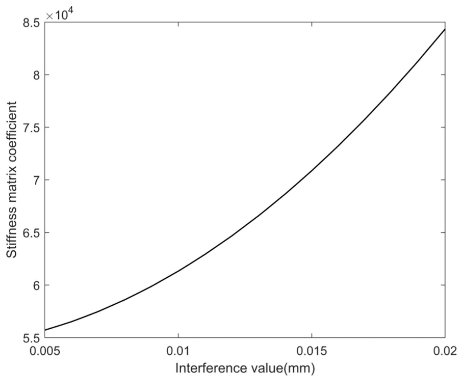
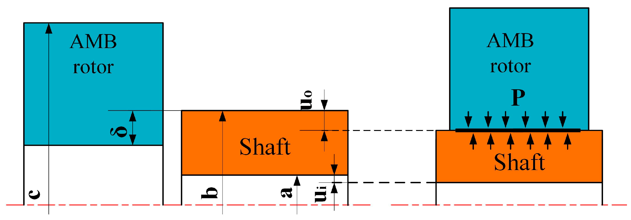
3.1. Effect of Interference Value on Rotor Stiffness

In the MSDS, many parts have interference-fit relationships to ensure the high speed and stable operation of the rotor system. The AMB rotor is a component of the active magnetic bearing. The AMB rotor is suspended under the magnetic force of the electromagnet, and is connected with the shaft by interference fit to support the rotor system. When there is an interference value between the AMB rotor and the shaft, contact pressure will be generated on the mating surface. This will cause the inner diameters and outer diameters of the AMB rotor to expand, and the inner diameters and outer diameters of the shaft to be compressed. Under the action of contact pressure, the AMB rotor is tightly connected to the shaft. The schematic diagram of its coordination is shown in Figure 2.
The contact pressure P between the AMB rotor and shaft on the mating surface is [28]:
P = δ b E 2 ( c 2 + b 2 c 2 b 2 + ν 2 ) + b E 1 ( b 2 + a 2 b 2 a 2 ν 1 )
where δ is the interference value, E1 and ν1 are the elastic modulus and Poisson’s ratio of the shaft, E2 and ν2 are the elastic modulus and Poisson’s ratio of the AMB rotor, a and b are the inner diameters and outer diameters of the shaft, and c is the outer diameter of the AMB rotor.
The contact pressure P is uniformly and symmetrically distributed in space. According to the Lame equation, the radial stress σ and radial displacement u on the shaft are [29]:
{ σ = b 2 P ( b 2 a 2 ) ( 1 a 2 r 2 ) u = b 2 P E 1 ( b 2 a 2 ) [ ( 1 + ν 1 ) a 2 r + ( 1 ν 1 ) r ]
where r is the radius from the interface to the center of rotation, and the radial stress σ is linearly related to the radial displacement u. The radial displacement ui and uo on the inner surface and outer surface of the shaft can be expressed as:
{ u i = b 2 P E 1 ( b 2 a 2 ) [ ( 1 + ν 1 ) a 2 a + ( 1 ν 1 ) a ] u o = b 2 P E 1 ( b 2 a 2 ) [ ( 1 + ν 1 ) a 2 b + ( 1 ν 1 ) b ]
The displacement of any section in the shaft element can be represented by the displacement of the element nodes. The micro-unit with a thickness of ds inside the element is taken, and the bending elastic potential energy of the micro-unit is:
d V s = 1 2 E I { x n y n } T { x n y n } d s
the equation of I is:
I = π 64 [ ( b u o ) 4 ( a u i ) 4 ]
The strain energy of the micro-unit is the work done by the radial stress. The cross-section of the area between the occurrence of radial deformation and no radial deformation on the outer surface of the micro-unit is an annular region. The radial displacement of the outer surface is relatively small. Therefore, the annular region can be unfolded and approximated as a rectangle region. Under the action of contact pressure P, the strain energy of this micro-unit is:
d W s = 1 2 π b σ u o { x n y n } T { x n y n } d s
The total potential energy of this micro-unit is:
d P s = 1 2 [ E I + π b σ u o ] { x n y n } T { x n y n } d s
Assuming that the full length of the shaft element is l. After organizing the above equation and integrating it along the full length l of the element, the potential energy Ps of the shaft element is obtained as:
P s = 1 2 { u 1 s } T [ K s ] { u 1 s } + 1 2 { u 2 s } T [ K s ] { u 2 s }
where { u 1 s } and { u 2 s } are the displacement of the nodes at both ends of the shaft element, and Ks is the rotor stiffness:
[ K s ] = E I + π b σ u o l 3 [ 12   6 l - 12   6 l 6 l   4 l 2 - 6 l   2 l 2 - 12   - 6 l     12   - 6 l 6 l   2 l 2 - 6 l   4 l 2 ]
The above equation is the equation of rotor stiffness after considering the interference-fit value. K i = E I + π b σ u o represents the rotor stiffness matrix coefficient. When the interference value δ increases from 0.005 mm to 0.02 mm, the variation curve of Ki at node 1 is shown in Figure 3. It is evident that with the increase in interference value, the rotor stiffness matrix coefficient tends to increase.

3.2. Interval Method Model Based on Chebyshev Polynomials

The uncertain parameters can be represented by interval parameters with known upper and lower bounds, so the interference value can be expressed in interval form as:
δ i = [ δ _ , δ ¯ ]
where δ i is the parameter interval of the interference value, δ _ is the lower bound of the interference value, and δ ¯ is the upper bound of the interference value. The stiffness interval of the corresponding nodes on the inner and outer rotors can be expressed as K i = [ K 1 i K 2 i K r i ] T ,
K a i = [ K a _ , K a ¯ ] = [ K a c β K a c , K a c + β K a c ] a = 1 , 2 , r
where K a i is the parameter interval of stiffness, K a _ is the lower bound of stiffness, K a ¯ is the upper bound of stiffness, K a c is the median of the stiffness interval, and β indicates the uncertain degree of stiffness K. The system motion equation under the uncertainty of the interference value can be expressed as:
M q ¨ ( t ) + C q ˙ ( t ) + K I q ( t ) = F ( t )
where K I is the overall stiffness matrix of the system that includes K i . The solution of Equation (16) can be expressed as:
q I ( K I , t ) = { q : M q ¨ + C q ˙ + K q = F , q ( t 0 ) = q 0 , K K I }
The above equation can be solved by Chebyshev polynomials.
When the number of uncertain interval variables is r, Equation (17) in multidimensional form can be expressed via Chebyshev polynomials as:
q I ( K I , t ) k 1 = 0 n k r = 0 n ( 1 2 ) l q ˜ k 1 , , k r C k 1 , , k r ( K I )
where n is the expansion order, l represents the number of occurrences of 0 in the subscript k 1 , , k r , and C k 1 , , k r ( K I ) is a multidimensional Chebyshev polynomial that can be expressed as:
C k 1 , k 2 , , k r ( K I ) = cos k 1 θ 1 cos k 2 θ 2 cos k r θ r
where q ˜ k 1 , , k r represents the Chebyshev coefficient, which can be calculated using the Gauss–Chebyshev polynomial:
q ˜ k 1 , , k r ( 2 m ) r j 1 = 1 m j r = 1 m q ˜ ( t , cos θ j 1 , cos θ j r ) cos k 1 θ j 1 cos k r θ j r
where m represents the number of interpolation points in each dimension, and mn + 1, q ˜ ( t , cos θ j 1 , cos θ j r ) is the deterministic response solution of the system at the interpolation point at each time step. The θ j r is the interpolation point that can be expressed as:
θ j r = 2 j r 1 m π 2 , j r = 1 , 2 , , m
when uncertain variables are defined in arbitrary intervals that can be transformed into standard intervals by transformations [19].

4. Numerical Results

4.1. Verification of Stiffness Equation

To ensure the correctness of the equation for the influence of interference value on rotor stiffness derived in the previous paper, the calculation results were verified by considering two extreme working conditions.
When the shaft and AMB rotor are integrated, the rotor stiffness is the sum of the shaft stiffness and AMB rotor stiffness, and the rotor stiffness is the highest, which is the upper bound of the stiffness. When there is no contact between the shaft and the AMB rotor, the influence of interference value on the rotor stiffness is ignored, and only the stiffness of the shaft is considered. The rotor stiffness is the minimum, which is the lower bound of stiffness. The upper and lower bounds of the transient response of disc 1 with maximum and minimum rotor stiffness are shown in the red and green curves in Figure 3. The interference value between the shaft and the AMB rotor is 0.015 mm, and the unbalances are located in discs 2 and 3. The eccentricity of the discs is e = 2 × 10⁻⁵ m, and the angular speed ratio is rw = 1.2. When the MSDS is started with angular acceleration α = 500 rad/s2, the transient deterministic response of disc 1 is shown by the black curve in Figure 4.
In Figure 4 it can be observed that when the interference value is 0.015 mm, the transient response curve of the MSDS can be completely enveloped by the upper and lower boundary curves of the rotor transient response at the maximum and minimum rotor stiffness. The above calculation results can demonstrate that the equation for the influence of interference value on rotor stiffness derived in this paper is reasonable and effective.

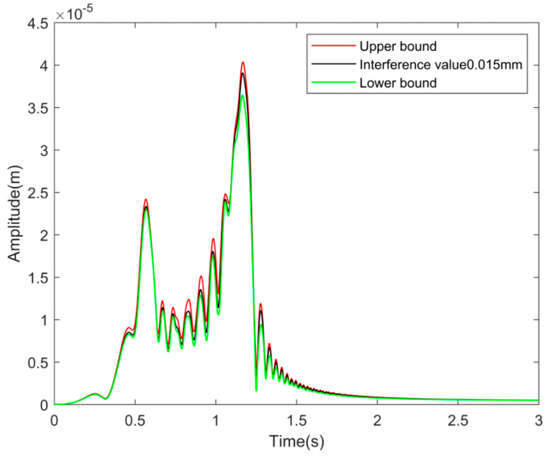
4.2. Transient Response Analysis

The interference value is easily affected by manufacturing errors, operating conditions, and other factors. At static or low angular speed, the uncertain degree of interference value is small. When the temperature or angular speed increases, the interference value will undergo great changes and the uncertain degree will increase. Therefore, the transient response of the system during acceleration under different uncertain degrees of the interference value is studied.
Define Z as the amplitude, Z ¯ as the upper bound of the response amplitude, Z _ as the lower bound of the response amplitude, Z c as the deterministic response amplitude, Δ Z as the uncertain value of the response amplitude, and define Δ Z = max ( Z c Z _ , Z ¯ Z c ) . To represent the uncertain degree of system response, define:
λ = Δ Z Z c
The interference value between the shaft and the AMB rotor is 0.015 mm, with a degree of uncertainty of 60%. The transient response of disc 1 during the acceleration start of the MSDS is shown in Figure 5. The transient response of disc 1 when the uncertain degree of interference value is within the range of [10%, 90%] is shown in Figure 6. It is evident that the impact of uncertain interference value on the response of the MSDS is mainly concentrated in the area where the angular speed is less than 1000 rad/s, especially around the angular speed ω = 580 rad/s. This is the resonance peak point corresponding to the first-order bending mode of the system, and the uncertainty of interference value has the greatest impact on the rotor response. In other angular speed regions, the rotor response is less affected by the uncertainty of interference value. As the uncertain degree of interference value increases, the response range of the rotor tends to increase, especially at the resonance peak point corresponding to the first-order bending mode.
According to Equation (22), calculate the relationship between the uncertain degree of the response and the uncertain degree of the interference value during the entire acceleration process of the MSDS. The calculation results are shown in Figure 7. It is evident that as the uncertain degree of the interference value increases, the uncertain degree of the response tends to increase, and is approximately in a power-function relationship with the uncertain degree of the interference value. The maximum uncertain degree of the rotor response is close to 5%.

4.3. Steady-State Response Analysis

This section will study the steady-state response of the MSDS under the uncertainty of the interference value. The interference value between the shaft and the AMB rotor is 0.015 mm. Use “” represents the position of the shaft center at a certain time, and “*” represents the position of the shaft center at subsequent times.

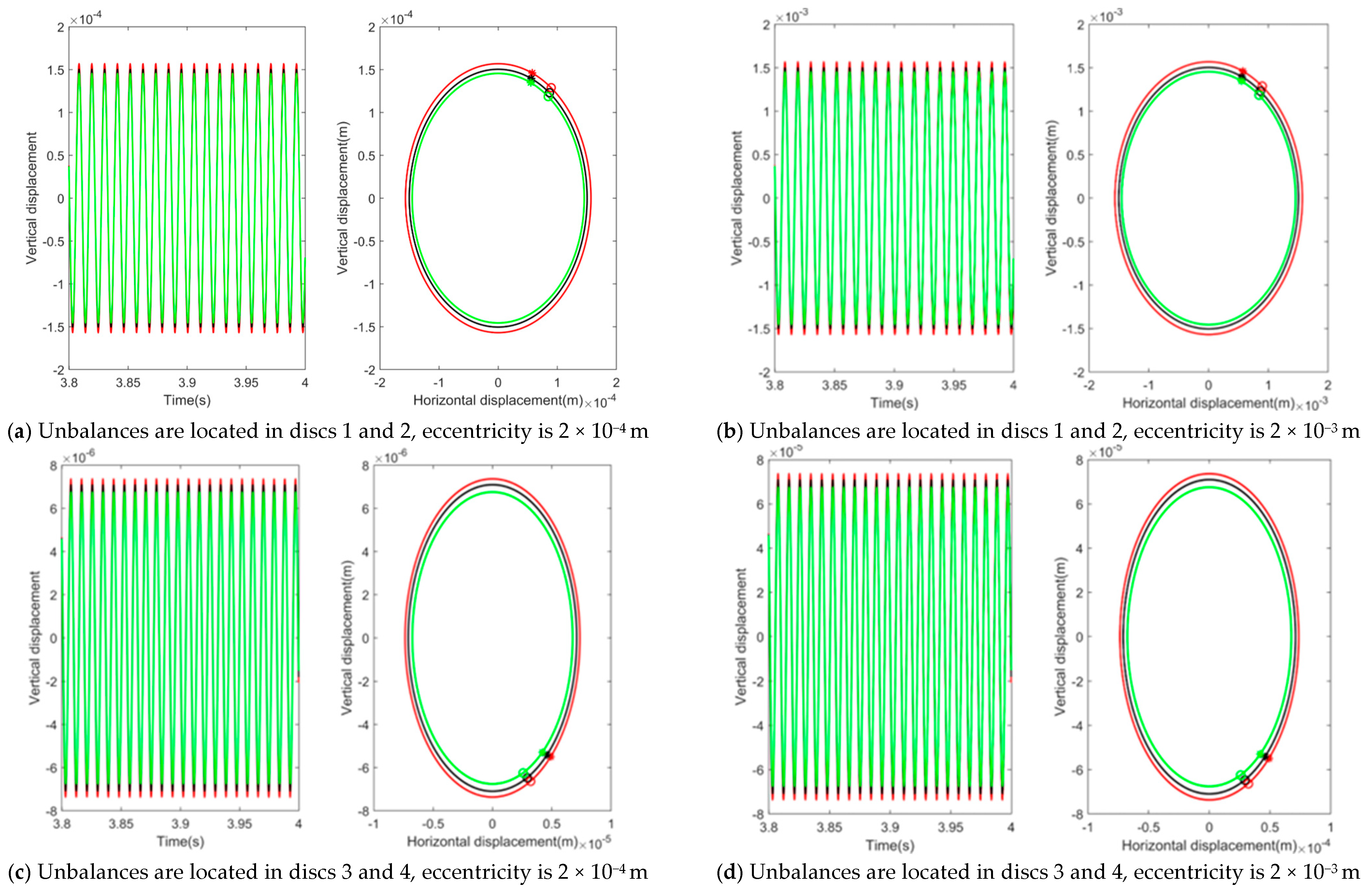
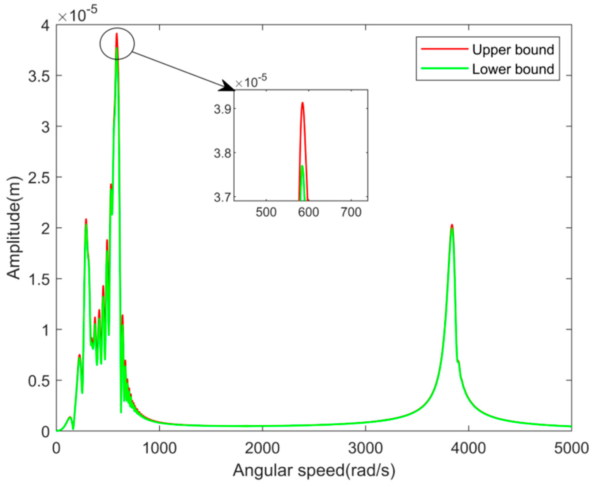
4.3.1. Influence of Unbalance on Steady-State Response

Rotor imbalance is a typical fault feature in a rotor system, and the position and value of the unbalance can lead to differences in rotor response. By changing the position of the unbalance and the eccentricity e, taking the internal rotor angular speed ω = 580 rad/s as an example, the steady-state response and axis trajectory of disc 1 are analyzed. The steady-state response and axis trajectory of disc 1 are shown in Figure 8a–d.
As shown in Figure 8, when the unbalances are only located on the inner rotor discs 1 and 2 or the outer rotor discs 3 and 4, the rotor axis trajectory appears as a single ellipse. This is because when the unbalances are only located on the inner or outer rotor, there is only a corresponding inner or outer rotor rotation frequency. The vortex direction of the MSDS with uncertain interference value is the same as that of the deterministic rotor system. From Figure 8, it can also be seen that the influence of the unbalances located in the inner rotor on the dynamic response of the system is much greater than that of the unbalances located in the outer rotor on the dynamic response of the system. According to the definition in the previous paper, it can be determined that the uncertain degree of response is approximately 4.3% when the unbalances are located in discs 1 and 2, with an eccentricity of 2 × 10⁻⁴ m, and the uncertain degree of response is approximately 4.4% when the eccentricity is 2 × 10⁻³ m. When the unbalances are located in discs 3 and 4 with an eccentricity of 2 × 10⁻⁴ m, the uncertain degree of response is approximately 4.9%. When the eccentricity is 2 × 10⁻³ m, the uncertain degree of response is still approximately 4.9%. This indicates that under the same uncertain degree of interference value, the position and value of the unbalances have little effect on the uncertain degree of the rotor response. When the unbalances are only located on the inner or outer rotor, the uncertain degree of the rotor response is almost unaffected by the value of the unbalances.

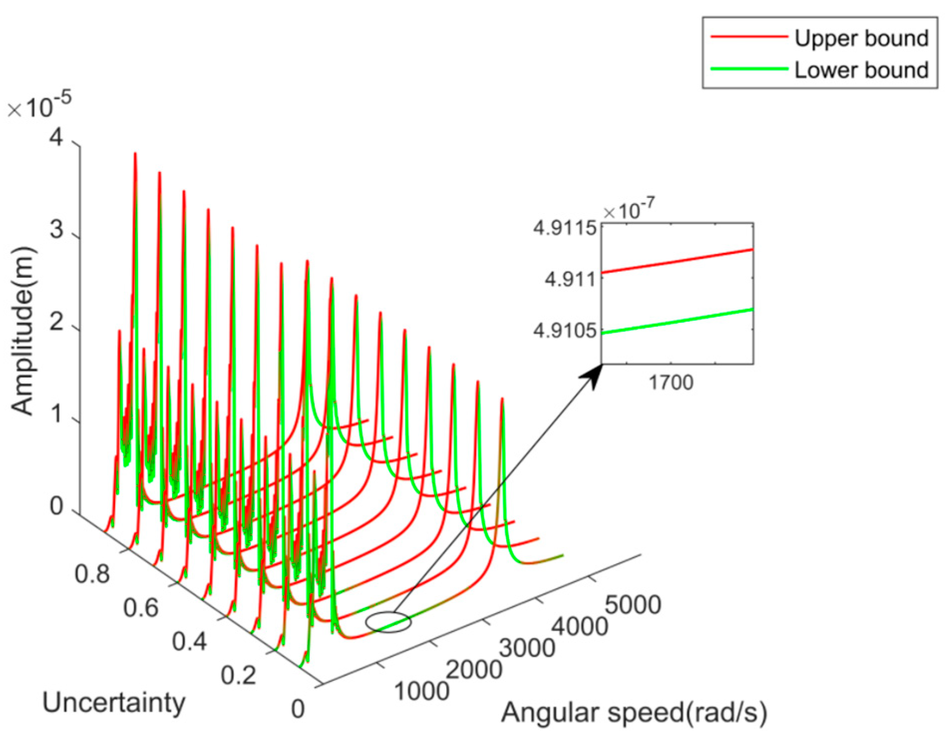
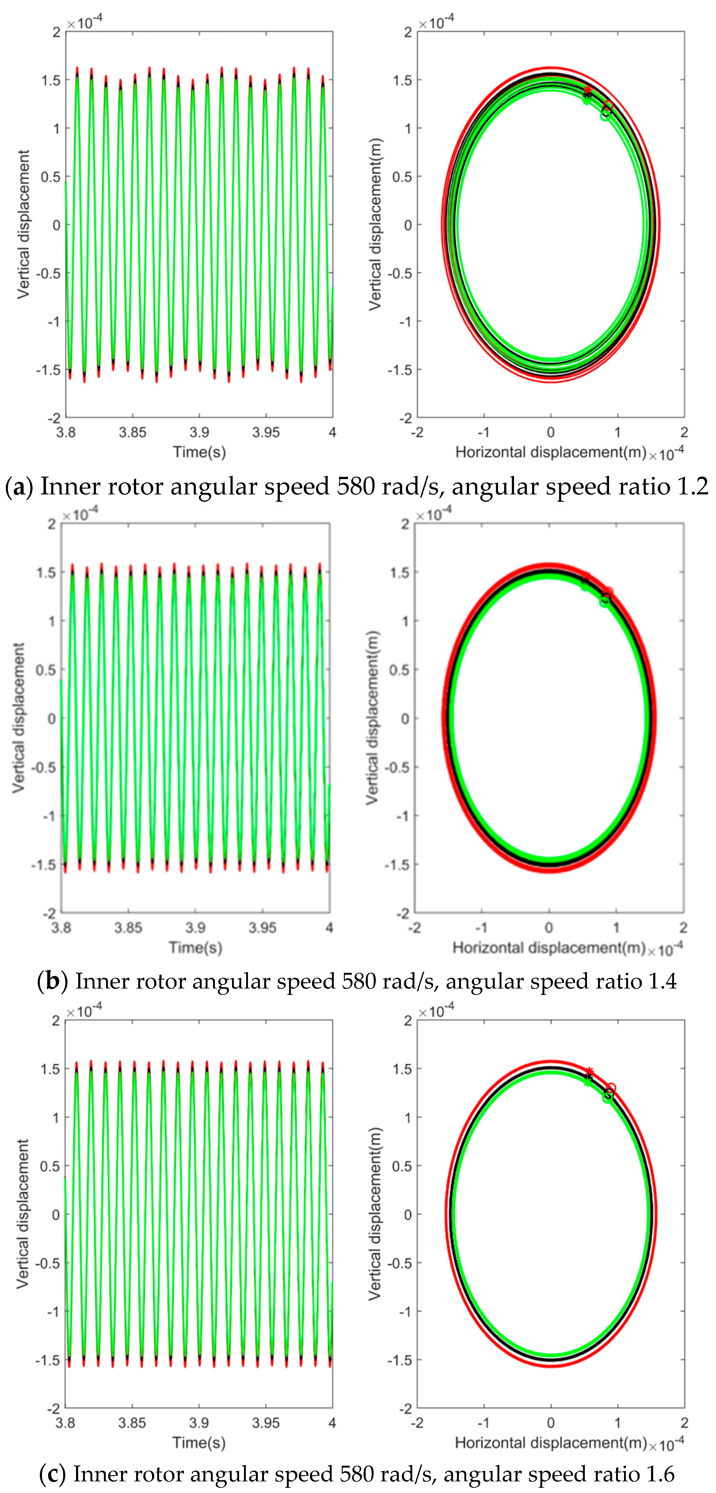
4.3.2. Influence of Angular Speed Ratio on Steady-State Response

The angular speed ratio is a unique and important parameter of the MSDS compared with the magnetically suspended rotor system, which has a great impact on the rotor axis trajectory and motion period. There are unbalances on both the inner rotor discs 1 and 2 and the outer rotor disc 3, changing the angular speed ratio ru, and taking the inner rotor angular speed ω = 580 rad/s as an example. The steady-state response and axis trajectory of disc 1 are analyzed. The steady-state response and axis trajectory of disc 1 are shown in Figure 9a–c.
As shown in Figure 9, when there are unbalances on discs 1, 2, and 3, the rotor axis trajectory appears as an intertwined ring. This is because when there are unbalances on both inner and outer rotors, there will be two rotor rotations with different frequencies. As the angular speed ratio increases, the rotor motion period will decrease. At an angular speed of 580 rad/s and an angular speed ratio of 1.2, the uncertain degree of rotor response is approximately 4.4%. At an angular speed ratio of 1.4, the uncertain degree of rotor response is approximately 4.2%. At an angular speed ratio of 1.6, the uncertain degree of rotor response is approximately 4.3%. This indicates that although different angular speed ratios can cause differences in rotor axis trajectory and motion period, the uncertain degree of rotor response is less affected by the angular speed ratio under the same uncertain degree of interference value.

5. Conclusions

This paper establishes a dynamic model of the MSDS, deduces the mechanism of the influence of interference value on the bending stiffness of the rotor, and analyzes the dynamic response characteristics of the MSDS based on the Chebyshev interval method when there is uncertainty in interference value. The following conclusions are drawn.
The equation for the effect of interference fit on rotor stiffness established in this paper is applicable to rotor models with interference-fit relationships.
The uncertainty of the interference value has a relatively large effect on the uncertain degree of the response at the resonance peak point corresponding to the first-order bending mode of the MSDS. In other angular speed regions, the effect of changes in uncertain degrees of interference value on rotor response is relatively small.
The effects of the structural and operational parameters on the dynamic response of the MSDS under uncertainty of interference value is studied by changing the unbalances and the angular speed ratio. The research results show that under the same uncertain degree of interference value, the change in unbalances and angular speed ratio has a relatively small influence on the uncertain degree of the rotor response.

Author Contributions

Conceptualization, N.W. and W.T.; methodology, N.W.; software, W.T.; validation, W.T.; formal analysis, N.W.; investigation, W.T.; resources, N.W.; data curation, W.T., M.L. and Y.N.; writing—original draft, W.T.; writing—review & editing, N.W.; visualization, M.L. and Y.N.; supervision, N.W.; project administration, W.T.; funding acquisition, N.W. All authors have read and agreed to the published version of the manuscript.

Funding

This research was funded by the National Natural Science Foundation (Grant No. 51975427).

Data Availability Statement

Not applicable.

Conflicts of Interest

The authors declare that there are no conflicts of interest regarding the publication of this paper.

References

  1. Hu, Y.; Zhou, D.; Jiang, Z. Basic Theory and Application of Magnetic Bearings; Mechanical Industry Press: Beijing, China, 2006; pp. 7–8. [Google Scholar]
  2. Li, S.; He, Z.; Zhao, P. Study on the design method of interference fit between gear and shaft of automobile transmission. J. Phys. Conf. Ser. 2021, 1885, 052067. [Google Scholar] [CrossRef]
  3. Hu, C.; Yu, H.; Xia, Z.; Gu, B. Flexible assembly research for cylindrical interference fit with form error in shaft-hole structures. Proc. Inst. Mech. Eng. 2023, 237, 203–215. [Google Scholar] [CrossRef]
  4. Liu, S.; Chen, X.; Song, C.; Zhu, C.; Bai, H.; Fuentes-Aznar, A. Influence of gear-shaft interference fit assembly on the meshing characteristics of cylindrical gears considering comprehensive modifications. Mech. Mach. Theory 2023, 182, 105247. [Google Scholar] [CrossRef]
  5. Suo, H.; Wei, Z.; Luo, B.; Wang, L.; Zhang, K.; Liang, B.; Deng, K.; Cheng, H. Interfacial wear damage mechanism between Ti-alloy and Al-alloy in interference-fit joint and influence of surface coatings: Experimental and numerical study. Eng. Fail. Anal. 2023, 143, 106931. [Google Scholar] [CrossRef]
  6. Shu, Y.; Yang, G.; Liu, Z. Experimental study on fretting damage in the interference fit area of high-speed train wheels and axles based on specimen. Eng. Fail. Anal. 2022, 141, 106619. [Google Scholar] [CrossRef]
  7. Lanoue, F.; Vadean, A.; Sanschagrin, B. Finite element analysis and contact modelling considerations of interference fits for fretting fatigue strength calculations. Simul. Model. Pract. Theory 2009, 17, 1587–1602. [Google Scholar] [CrossRef]
  8. Wang, Z.; Wang, Z.; Bai, X.; Zhang, X.; Wang, Y. Effect of interference fit on dynamic characteristics of spindle rotor system. J. Braz. Soc. Mech. Sci. Eng. 2022, 44, 316. [Google Scholar] [CrossRef]
  9. Güven, F. Effect of design parameters on stresses occurring at the tooth root in a spur gear pressed on a shaft. Proc. Inst. Mech. Eng. Part E J. Process Mech. Eng. 2021, 235, 1164–1174. [Google Scholar] [CrossRef]
  10. Pedersen, N.L. On optimization of interference fit assembly. Struct. Multidisc. Optim. 2016, 54, 349–359. [Google Scholar] [CrossRef]
  11. Gruescu, C.M.; Davidescu, A.; Sticlaru, C.; Lovasz, E.C. Interference Fits. Bearing Capacity Under Complex Loading-FEM Analysis. New Adv. Mech. Mech. Transm. Robot. 2020, 88, 403–414. [Google Scholar]
  12. Storti, G.C.; Fonçatti, L.G. Rotordynamic Influence of a Spider Mounted on Shaft with Interference Fit in an Electric Machine Rotor. In Proceedings of the 10th International Conference on Rotor Dynamics-IFToMM; Springer International Publishing: Berlin/Heidelberg, Germany, 2018; Volume 61, pp. 530–546. [Google Scholar]
  13. Kovan, V. Separation frequency analysis of interference fitted hollow shaft-hub connections by finite element method. Adv. Eng. Softw. 2011, 42, 644–648. [Google Scholar] [CrossRef]
  14. Vishwakarma, N.; Renuke, A.; Phalle, V. Effect of Tapered Interference Fit between Impeller and Shaft in Turbo Machines. Stroj. Cas. J. Mech. Eng. 2018, 68, 25–32. [Google Scholar] [CrossRef]
  15. Wang, J.; Yang, Y.; Zheng, Q.; Deng, W.; Zhang, D.; Fu, C. Dynamic Response of Dual-Disk Rotor System with Uncertainties Based on Chebyshev Convex Method. Appl. Sci. 2021, 11, 9146. [Google Scholar] [CrossRef]
  16. Zhao, S.; Ren, X.; Zheng, Q.; Lu, K.; Fu, C.; Yang, Y. Transient dynamic balancing of the rotor system with uncertainty. Mech. Syst. Signal Process. 2022, 171, 108894. [Google Scholar] [CrossRef]
  17. Jia, Z.; Yang, Y.; Zheng, Q.; Deng, W. Dynamic analysis of Jeffcott rotor under uncertainty based on Chebyshev convex method. Mech. Syst. Signal Process. 2022, 167, 108603. [Google Scholar] [CrossRef]
  18. Wang, C.; Ma, Y.; Zhang, D.; Hong, J. Interval Analysis on Aero-Engine Rotor System with Misalignment. In Proceedings of the ASME Turbo Expo 2015: Turbine Technical Conference and Exposition, Montreal, QC, Canada, 15–19 June 2015; Volume 7A, pp. 15–19. [Google Scholar]
  19. Fu, C.; Ren, X.; Yang, Y.; Xia, Y.; Deng, W. An interval precise integration method for transient unbalance response analysis of rotor system with uncertainty. Mech. Syst. Signal Process. 2018, 107, 137–148. [Google Scholar] [CrossRef]
  20. Fu, C.; Ren, X.; Yang, Y.; Lu, K.; Qin, W. Steady-state response analysis of cracked rotors with uncertain-but-bounded parameters using a polynomial surrogate method. Commun. Nonlinear Sci. Numer. Simul. 2019, 68, 240–256. [Google Scholar] [CrossRef]
  21. Chen, Y.; Guo, C. An interval fault diagnosis method for rotor cracks. Comput. Electr. Eng. 2020, 87, 106752. [Google Scholar] [CrossRef]
  22. Ma, Y.; Wang, Y.; Wang, C.; Hong, J. Interval analysis of rotor dynamic response based on Chebyshev polynomials. Chin. J. Aeronaut. 2020, 33, 2342–2356. [Google Scholar] [CrossRef]
  23. Ma, Y.; Wang, Y.; Wang, C.; Hong, J. Nonlinear interval analysis of rotor response with joints under uncertainties. Chin. J. Aeronaut. 2020, 33, 205–218. [Google Scholar] [CrossRef]
  24. Lara-Molina, F.A.; Cavalini, A.A., Jr.; Koroishi, E.H.; Steffen, V., Jr. Sensitivity Analysis of Flexible Rotor Subjected to Interval Uncertainties. Lat. Am. J. Solids Struct. 2019, 16. [Google Scholar] [CrossRef]
  25. Hao, Y.; Chen, M.; Hong, J.; Ma, Y. Interval analysis method of rotordynamics based on Taylor expansion method. J. Aerosp. Power 2014, 29, 571–577. [Google Scholar]
  26. Barbosa, P.C.P.F.; Lara-Molina, F.A.; da Silva, I.B.; Cavalini, A.A., Jr.; Steffen, V. Uncertain and sensitivity analyses of a composite shaft. Meccanica 2020, 55, 35–48. [Google Scholar] [CrossRef]
  27. Yang, Y.; Cao, D.; Wang, D.; Jiang, G. Fixed-point rubbing characteristic analysis of a dual-rotor system based on the Lankarani-Nikravesh model. Mech. Mach. Theory 2016, 103, 202–221. [Google Scholar] [CrossRef]
  28. Xu, Z. Elasticity; Higher Education Press: Beijing, China, 1984. [Google Scholar]
  29. Zhuo, W. Applied Elastoplastic Mechanics; Science Press: Beijing, China, 2013. [Google Scholar]
Figure 1. Structural diagram of the magnetically suspended dual-rotor system.
Actuators 13 00033 g001
Figure 2. Structural diagram of interference fit between AMB rotor and shaft.
Actuators 13 00033 g002
Figure 3. The variation of stiffness matrix coefficient with interference value at node 1.
Actuators 13 00033 g003
Figure 4. Transient time-domain response of disc 1.
Actuators 13 00033 g004
Figure 5. Transient response of disc 1 when the uncertain degree of interference value is 60%.
Actuators 13 00033 g005
Figure 6. Transient response of disc 1 under a different uncertain degree of interference value.
Actuators 13 00033 g006
Figure 7. The relationship between the uncertain degree of rotor response and the uncertain degree of interference value during acceleration.
Actuators 13 00033 g007
Figure 8. Steady−state time−domain response and axis trajectory of disc 1.
Actuators 13 00033 g008
Figure 9. Steady−state time−domain response and axis trajectory of disc 1.
Actuators 13 00033 g009
Table 1. Main parameters of the magnetically suspended dual-rotor system.
TitleValueTitleValue
Inner rotor
length(m)
0.706Outer rotor length(m)0.5011
Inner rotor outer
radius(m)
0.0125Outer rotor outer radius(m)0.02
Inner rotor inner
radius(m)
0.0075Outer rotor inner radius(m)0.015
Inner rotor density
(kg/m3)
7850Outer rotor density(kg/m3)7850
Elastic modulus of
the inner rotor (Pa)
2.1 × 10¹¹Elastic modulus of the outer rotor(Pa)2.1 × 10¹¹
Poisson ratio of
inner rotor
0.3Poisson ratio of outer rotor0.3
Inner rotor disc
density(kg/m3)
7928.56Outer rotor disc density(kg/m3)7928.56
Inner rotor disc
thickness(m)
0.0273Outer rotor disc thickness(m)0.0273
Outer radius of
disc 1(m)
0.125Outer radius of disc 3(m)0.125
Inner radius of
disc 1(m)
0.0125Inner radius of disc 3(m)0.02
Outer radius of
disc 2(m)
0.125Outer radius of disc 4(m)0.125
Inner radius of
disc 2(m)
0.0125Inner radius of disc 4(m)0.02
Disclaimer/Publisher’s Note: The statements, opinions and data contained in all publications are solely those of the individual author(s) and contributor(s) and not of MDPI and/or the editor(s). MDPI and/or the editor(s) disclaim responsibility for any injury to people or property resulting from any ideas, methods, instructions or products referred to in the content.

