Article

Standalone and Interconnected Analysis of an Independent Accumulator Pressure Compressibility Hydro-Pneumatic Suspension for the Four-Axle Heavy Truck

by
Thiyagarajan Jayaraman
and
Muthuramalingam Thangaraj
*
Department of Mechatronics Engineering, College of Engineering and Technology, SRM Institute of Science and Technology, SRM Nagar, Kattankulathur, Chengalpattu 603203, Tamil Nadu, India
*
Author to whom correspondence should be addressed.
Actuators 2023, 12(9), 347; https://doi.org/10.3390/act12090347
Submission received: 30 June 2023 / Revised: 14 August 2023 / Accepted: 25 August 2023 / Published: 28 August 2023

Abstract

:
This paper has proposed a new hydro-pneumatic damper, allowing independent accumulator pressure compressibility from the chamber pressure which enhances isolation performances due its lower F-V hysteresis effect at moderate velocities. The system utilizes the generic hydraulic damper with two hydro-pneumatic accumulators and four check valves in its design. To evaluate the active suspension capability of proposed damper effectiveness, a 22-degrees-of-freedom (DOF), four-axle truck model is integrated with a hydraulic control valve, which is built in an LMS-AME sim environment. Then, the model is exported as an S-function into Matlab/Simulink co-simulation platform for the hydraulic servo-valve control input of a model predictive control (MPC) and proportional-integral-derivative (PID) output signal. Simulation results show that the MPC and an additional supply of fluid to the proposed damper provide better performances and an adaptive damping capability is established. This work also showcases the development and results of a roll interconnected suspension study to assess the proposed damper characteristics when it is interconnected. The various advantages of the proposed-HPIS system over the well-known hydraulic interconnected system (HIS) and hydro-pneumatic interconnected suspension (HPIS) system are studied.

1. Introduction

1.1. Introduction to Hysteresis

In the past decades, truck suspension researchers proposed many modifications in pneumatic suspensions due to the major advantage of stiffness of the air-spring according to internal pressure characteristics [1,2,3,4]. Quaglia and Sorli, Porumamila et al., and Nieto et al. have examined the auxiliary pneumatic tank integrated air suspension, where the pneumatic pressure between the air-spring and tank is controlled by the valves and pipes [5]. A double-acting type pneumatic cylinder system was proposed which is able to provide variable stiffness and adjust the ride altitude independently by regulating the chamber pressure of the pneumatic cylinder. But in practical usage, the proposed suspension system in heavy trucks is limited due to cost, weight, reliability, and sealing issues [6,7,8]. The hydro-pneumatic suspension is the one extensively used in heavy trucks and according to Bauer [9], most of the tractor front axles were hydro-pneumatic-suspended to provide comfort and vehicle handling. In the hydraulic damping system, the fluid stored in the chambers provides elastic energy due to oil compressibility. And the factors of flow, through orifices and pipes, sharp edges, restricting passages, losses in joints and bends, blow-off valves and Coulomb friction, etc., are all involved in hysteresis effects [10,11]. By increasing the oil and gas compressibility, the energy accumulated in the compression/rebound chamber also increases, which results in an increase in the hysteresis loop area [10,12,13,14].

1.2. Literature Review

In general, most of the existing hydro-pneumatic system gas pressure is almost equal to the respective chamber pressure because of its construction. Thus, at low compression/rebound piston velocity, the damping force will be the same and the width of the hysteresis between F-V curves will be much less. And at moderate velocities, the width of the curve is increased due to air compressibility behavior. At the higher velocities, the hysteresis effect is reduced due to sudden pressure changes. The moderate velocity hysteresis effect can be reduced by injecting the fluid into the chambers through the hydraulic control valve and by appropriate control logic [15]. Apart from this, many other designs of the hydro-pneumatic suspension system were evolved to improve the comfort of the vehicles. Els presented a hydro-pneumatic-based, four-state semi-active suspension which incorporates two damper packs with bypass valves and two gas accumulators. Both the accumulators were connected with the set of solenoid valves and the damping pack. By the solenoid valve switching, the spring and damping characteristics are varied, allowing the ride handling and comfort mode to be obtained [16]. Two different types of architectures of hydro-pneumatic-based, semi-active suspension to the quarter car model [17]. The double suspension system (DSS) has two different sizes and pressure accumulators, which are connected with the compression chamber of the double acting cylinder through the dissimilar electro valves. In the activation damper system (ADS), one electro valve is fitted in the common pipe to regulate the flux of one accumulator. This variable damping-stiffness system with the effective control algorithm delivers better comfort [5]. A pneumatic-based system was designed and proposed with independent stiffness and height-leveling ability. The pneumatic spring contains a double-acting cylinder and two accumulators that are connected separately to the cylinder rebound and compression chamber through similar orifices which again increases the hysteresis effect. The high-pressure gas supplied from the tank is controlled by a separate regulator and fed into the compression/rebound chambers of the pneumatic actuator [18]. The dual accumulator connected parallel with a single acting cylinder of hydro-pneumatic suspension was proposed by El-Tawab [19] to improve the comfort. Numerical simulation of the double accumulator system provides better results than the conventional system. The modified version of the dual accumulator type of hydro-pneumatic suspension system was presented by the authors of [20]. The main and secondary accumulators provide stiffness effects that are associated with an adjustable orifice to provide an additional damping effect [21]. When the piston moves up and down, the flow from the accumulator to chamber in and out, respectively, is accomplished through the valve block. And it is concluded that the performance can be enhanced considerably and optimized through the appropriate selection of the dual chamber damper parameters [22]. Youqun Zhao presented non-linear stiffness and damping with the compression and restoration valve system-based, hydro-pneumatic suspension. A pareto artificial fish swarm algorithm was used to optimize the heave centroid and pitch accelerations wherein the 4DOF half-vehicle model without a rolling effect was considered for the investigation. Even though these designs provide comfort, they are controlled by a solenoid control or adjustable orifice or controlled regulator and control valve. Hence, additional modifications are required to reduce the hysteresis effect in a passive hydro-pneumatic damper.
On the other side, the heavy trucks are involved in a high body roll, resulting in poor handling and rollover accidents. Thus, research on interconnected suspension of heavy trucks was also investigated from past decades. A multi-disciplinary approach of free and forced vibrations of a vehicle was performed in the 4DOF half-car model for the hydraulically interconnected suspension (HIS) [23,24]. The behavior of the anti-roll-equipped HIS system was investigated both by simulation and experimentation to identify the key parameters of comfort. An anti-pitch HIS system for two- and three-axle heavy vehicles was proposed by [25,26]. A pitch and roll independently tuned HIS system with a 14 DOF model was proposed by [27,28] with various road and braking/steering maneuvers. The pressure inside the interconnection and chamber of HIS must be high enough to produce the desired force with limited space. The additional accumulator increases the total weight of the vehicle [29]. The pneumatic pitch interconnected suspension for the 4DOF half-car model was modelled and optimized and it was reported that the pitch vibration is greatly suppressed. Subsequently, the hydro-pneumatic interconnected suspension (HPIS) system has also been investigated in the recent years [30,31,32]. The vehicle pitch, roll, bounce, and wrap model properties of the four-wheel suspension strut vehicle was analyzed under various types of HPIS configurations [32]. Overall (to our knowledge), the research area of the interconnected suspension hysteresis effect of the hydraulic and hydro-pneumatic system is still unexplored. Even though many research works have been available in automotive electronics, it was observed that only very few research works have been performed in HPIS systems [33,34,35].
The present work has therefore proposed a hydro-pneumatic, pressure-independent, velocity-dependent damper with a lower hysteresis effect to heavy trucks with a simple construction. The proposed systems were analyzed in two directions to assess the effectiveness of the damper. 1. The proposed system stand-alone damper is compared with the PID and MPC controlled hydro-pneumatic active suspension system to investigate the comfort criterion. 2. The proposed stand-alone damper is compared with the hydraulic interconnected (HIS) and hydro-pneumatic interconnected systems (HPIS) to identify the capability and hysteresis effects in the interconnected studies.

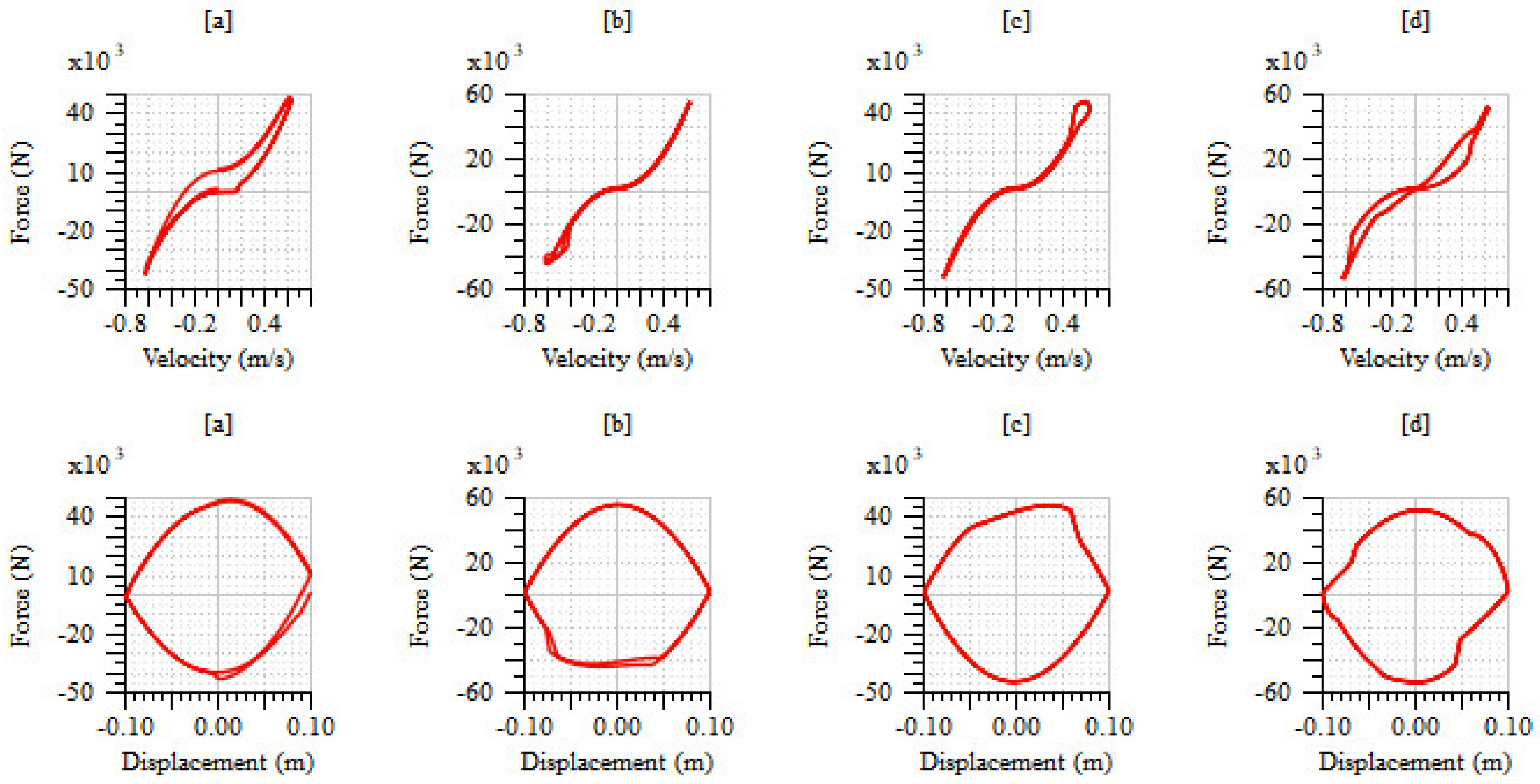
2. Modeling and Hysteresis Analysis of Various Dampers

The hysteresis between the output parameter and input parameters is typically asymmetric due to the fact that the input and output curves are shifted and upturned while moving towards the opposite direction [36]. Hence, the correlation between the input and output driving quantities (i.e., F-V) will be symmetric. Especially in the damping of the suspension system, the hysteresis effect between the F-V plays a very important role in the suspension control [37]. Thus, the flow through the piston orifice, accumulator, and oil and gas compressibility is considered for the hysteresis study of Figure 1.
The damper force can be calculated by
F d = P 2 .   A c P 1 .   A r

2.1. Modeling of an Orifice

The orifice computes the flow rate through an orifice at a given pressure differential. The utility is a double precision function that estimates the flow rate through an orifice from the following inputs.
d h = 4 A P w
In this case, the standard circular type piston orifice was used and assumed as the same as the orifice diameter. Then, the volumetric flow rate is defined as:
q = C q . A 2 P ρ
From the above relation, q/A infers the mean velocity of the fluid. In Equation (3), the volumetric flow rate against the change in the pressure has an infinite gradient and is physically impractical. The flow coefficient used is written as:
C q = C q m a x . t a n h 2 . λ λ c r i t
Here, the λ = D h ϑ . 2 P ρ ; for the λ λ c r i t , the values of C q = C q m a x are given. For low λ , the change in the pressure between the chambers of the piston is proportional. Then, the flow rate through the piston orifice from the rebound to the compression chamber Q 12 is expressed as
Q 12 = Q 21 = C q A 2 P 1 P 2 ρ . ρ ρ ( 0 ) s i g n ( P 1 P 2 )

2.2. Modeling of an Accumulator

The accumulator is modeled considering that the gas pressure and hydraulic pressure are equal, i.e.,
P g c = P L L ;   P g r = P L U
Volume of the gas is calculated as:
V g c = P a c P g c 1 γ . V a c ;   V g r = P a r P g r 1 γ . V a r

2.3. Modeling of an Chamber

Formula for calculating derivative pressure in terms of net flow rate and total volume
d P 1 d t = B ( P 1 ) . i Q 1 P 1 . ρ ( 0 ) ρ ( P 1 ) i v i + v o l 0
The following Figure 2 depicts the velocity-force (F-V) and displacement-force (F-D) diagram for various types of damper designs. Figure 2a depicts characteristics of non-linear hydraulic dampers, for which the low-speed region hysteresis is significantly higher than the other hydro-pneumatic systems. This is due to the end of compression and rebound stroking the pressure of the fluid, making it higher in the compression and rebound chambers, respectively. In the case of hydro-pneumatic system, gas is compressed and provides elastic energy. Therefore, all the hydro-pneumatic system low-speed regions were having a lower hysteresis effect. Figure 2b,c depicts the rebound chamber with an accumulator and the compression chamber with an accumulator without a check valve hydro-pneumatic damper model, respectively. The absence of the accumulator in either side causes an abrupt increase/decrease in force in the high-speed region. Figure 2d depicts the dual accumulator hydro-pneumatic system. The presence of the dual accumulator reduces the abrupt change in forces in the high-speed region. Also, there are no hysteresis effects in F-V characteristics during high-speed regions of both compression and rebound strokes (i.e., linear characteristics). But at the moderate velocities, the hysteresis loop is formed. Hence, the particular shapes of each damper governs the specific performances at particular frequencies and suspension controls [38,39,40,41]. If the particular F-V hysteresis effect is reduced, it will be possible to obtain the significant performance enhancement in the passive damper at a particular frequency range.

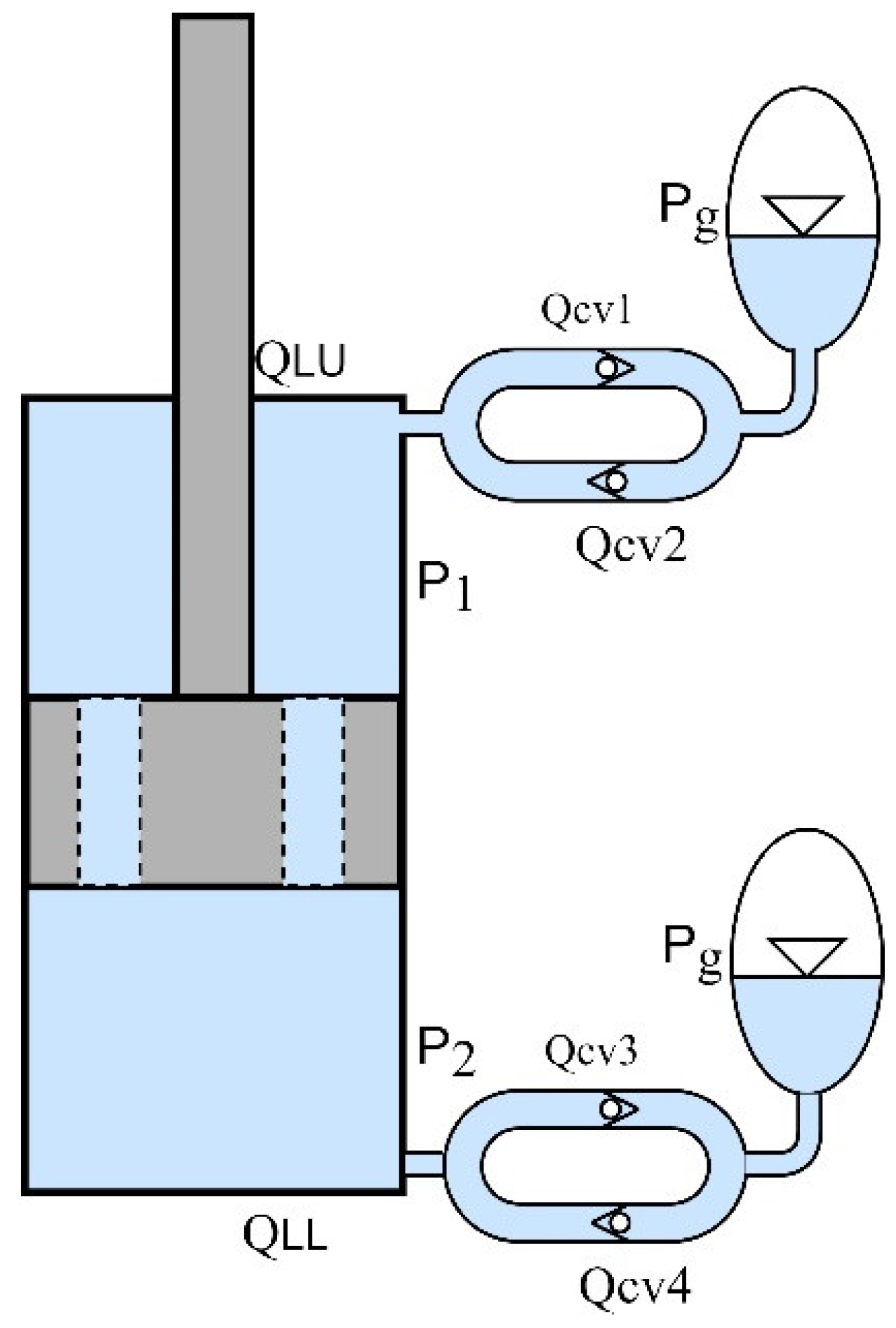
3. Construction and Analysis of Pressure Independent and Velocity Dependent Hydro-Pneumatic Damper

Figure 3 depicts the proposed chamber-pressure-independent and velocity-dependent hydro-pneumatic damper. The flow between the accumulator and piston compression/rebound chamber provides an additional damping effect and also the compression of the respective air spring provides a stiffness effect to the particular chamber. The structure between accumulator and chamber ensures the damping and stiffness characteristics. Unlike the existing hydro-pneumatic system, the gas pressure of the air spring is not directly proportional to the chamber hydraulic pressure. The difference between the upper ( P L U )/lower ( P L L ) accumulator fluid and rebound ( P 1 )/compression chamber ( P 2 ) is positive and if the pressure exceeds the particular check valve cracking pressure ( P c r a c k i ), then fluid flow from the accumulator to the respective chamber will take place through check valves 2 ( Q c v 2 ) and 4 ( Q c v 4 ), respectively. If the difference is negative and the variation exceeds the crack pressure of a particular check valve, then the flow from compression/rebound chamber to lower/upper accumulator will take place through check valves 1 ( Q c v 1 ) and 3 ( Q c v 3 ), respectively.

3.1. Check Valve

Static fractional valve opening of the check valve is given by:
x v i = P i P s a t i P c r a c k i
A c o = x v i . A v . m a x
If the P c v i is positive, the check valve will be open and the flow rate of the i t h valve is
Q C v i = P c v i . g r a d i
The pressure drop of the check valves can be written as
P c v i = Q c v i 2 ρ 2 c d 2 A c o i 2
The flow rates from the accumulators to chambers:
Q a c = Q c v 1 Q c v 2   :   Q a r = Q c v 3 Q c v 4 ;

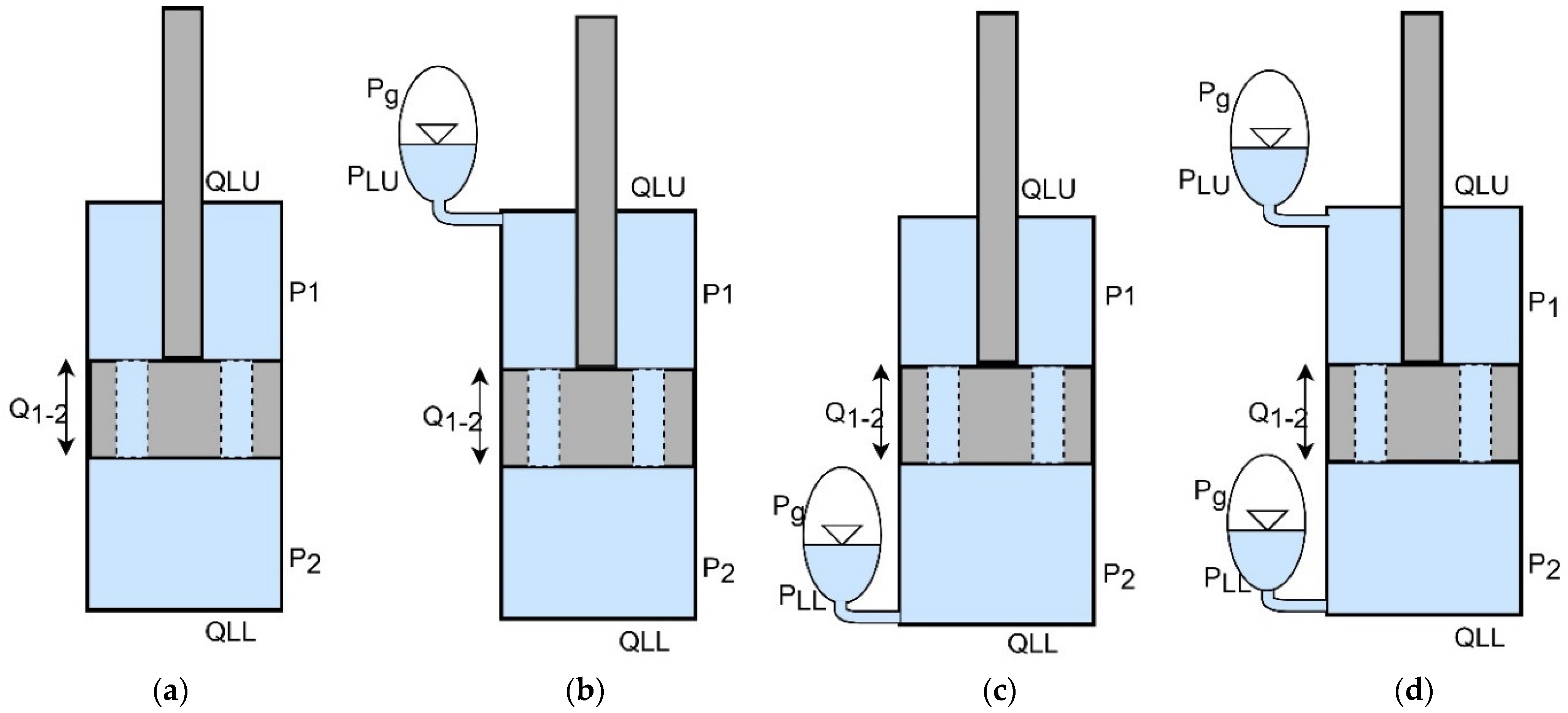
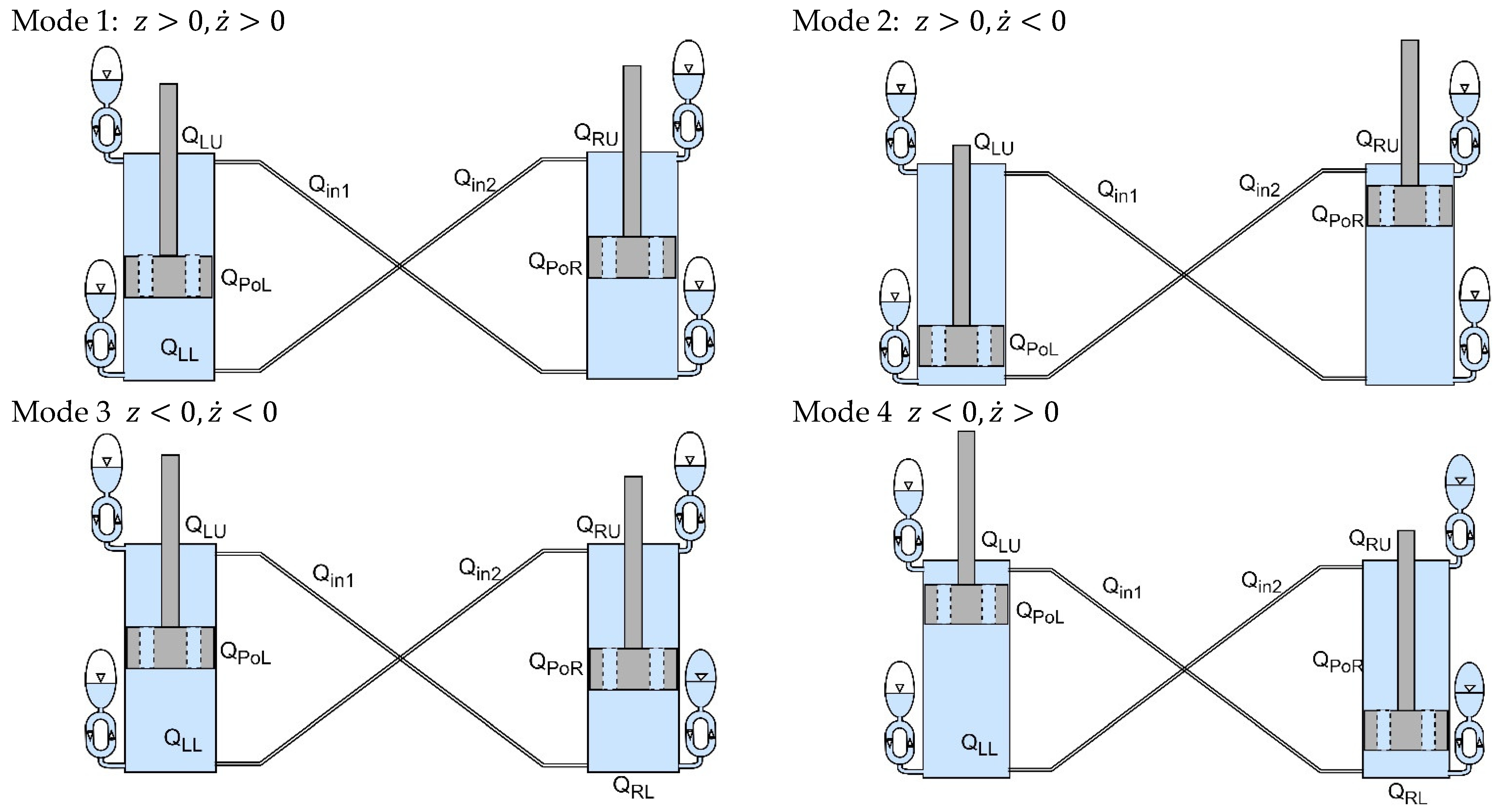
3.2. Working Principle

Check valve 1 supplies the flow rate of ( Q c v 1 ) to the accumulator when the P c v 1 is P 1 P L U P c r a c k 1 ; check valve 2 supplies the flow rate of ( Q c v 2 ) to the rebound chamber when the P c v 2 is P L U P 1 P c r a c k 2 , check valve 3 supplies the flow rate of ( Q c v 3 ) to the accumulator when the P c v 3 is P 2 P L L P c r a c k 3 , check valve 4 supplies the flow rate of ( Q c v 4 ) to the compression chamber when the P c v 4 is P L L P 2 P c r a c k 4 , respectively.
Mode 1:
z > 0 , z ˙ < 0
In this mode, the piston is moving from z m a x to the equilibrium position. The pressurized fluid in the rebound chamber is pushed through the piston orifice ( Q 12 ) and the check valves, so the damping of mode 1 is expressed as
2 Q 12 + Q c v 1 Q c v 2 Q c v 3 + Q c v 4 = z ˙ A c A r
Mode 2:
z < 0 , z ˙ < 0
In this mode, the piston is below the equilibrium position and moves towards the compression side. Then, the damping of mode 2 is expressed as
2 Q 21 Q c v 1 + Q c v 2 + Q c v 3 Q c v 4 = z ˙ A c A r
Mode 3:
z < 0 , z ˙ > 0
In this mode, the piston moves from the compression side end to the equilibrium position. Then, the fluid escapes from the compression chamber to the rebound chamber flow rate of ( Q 21 ) and check valves. Then, the equation for mode 3 is
2 Q 21 Q c v 1 + Q c v 2 + Q c v 3 Q c v 4 = z ˙ A c A r
Mode 4:
z > 0 , z ˙ > 0
In this position, the piston is moved from equilibrium position to the rebound side end. The working principle is very similar to mode 1. Hence, the equation of mode 4 is
2 Q 12 + Q c v 1 Q c v 2 Q c v 3 + Q c v 4 = z ˙ A c A r
Here, the flow rates of the piston orifice and check valve play an important role in this study. And the variation of the piston orifice flow rates makes a significant variation in the damping values. Hence, the piston orifice is selected based on the required damping. Thus, the piston orifice is kept constant during the various check valve flow rates analysis, which is shown in Figure 4.
In Figure 4, 0 L/min denotes no flow between chamber and accumulator through check valves. From this plot, it is identified that the zero-flow model has a dead zone and hysteresis effects in low-speed regions. And there is no hysteresis effect on the hydro-pneumatic system, when there is flow irrespective of flow rates. Figure 5 depicts the equivalent damping constant of hydraulic, hydro-pneumatic, and proposed damper force with respect to velocity plots. From this figure, it is identified that, at moderate velocities, the proposed system is working better than the pure hydraulic and hydro-pneumatic without a check valve system. In mode 3 at the 0.34 m/s, the force generated by hydraulic and hydro-pneumatic systems without check valves and the proposed systems are 14,412, 11,007, and 15,067 N, respectively. Similarly, in mode 4, the forces of the three mentioned systems are 25,842, 26,609, and 20,401 N, respectively. From modes 3 and 4, it is identified that the proposed system has less variation in the respective modes.

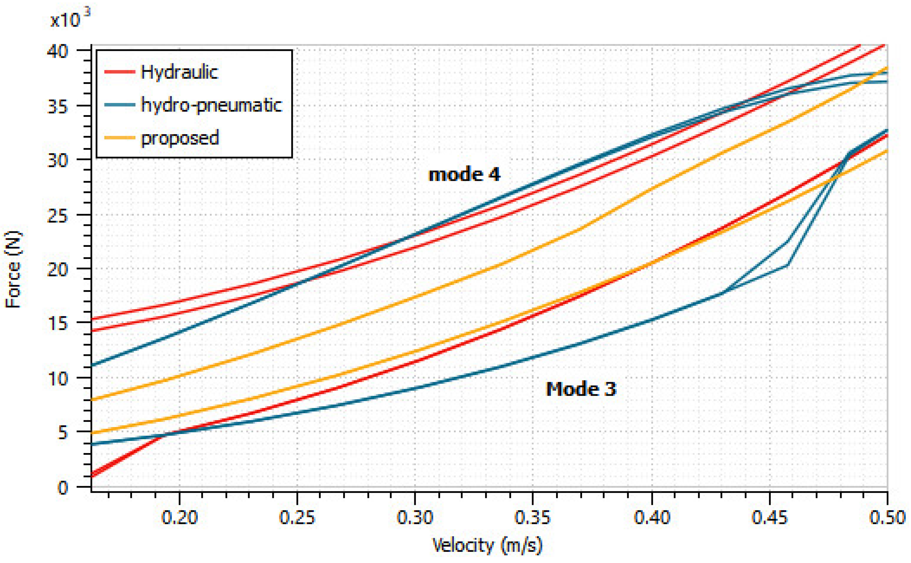
3.3. Influence of Check Valve

To identify the important characteristics of the vehicle and dampers, the 2DOF suspension model is widely used in literature [42]. Hence, the 2DOF suspension model is used to evaluate the influence of the check valve. The dynamic equation of the corresponding sprung and unsprung mass model is expressed as
m s z ¨ s = c s ( t ) z ˙ u s z ˙ s + k s ( t ) z u s z s
m u s z ¨ u s = c s t z ˙ s z ˙ u s + k s t z s z u s + c u s t z ˙ r z ˙ u s + k u s t z r z u s
where the values of m s ,   m u s ,   c u s , k s   &   k u s are set as 2100 kg, 600 kg, 6000 Ns/m, 102,600 N/m, and 180,000 N/m, respectively. Because of the proposed pressure-independent and velocity-dependent hydro-pneumatic damper, an additional stiffness was generated, unlike a regular damper and external mechanical spring combination. Thus, the above values considered for the check valve influence the simulation along with the random signal input values of −0.1 m min and 0.1 m max with the sample time of 0.1 s given as road input for this investigation. As shown in Figure 6 and Table 1, a significant improvement in sprung mass acceleration with the proposed system is achieved and compared with the hydro-pneumatic and hydraulic dampers. Specifically, HPD acceleration is higher at moderate frequencies and much lower at higher frequencies.
Due to the sudden rise and drop of the input signal and a sudden variation in pressure, the hydro-pneumatic system chamber pressure directly compresses the gas. Hence, the sprung mass acceleration is increased. The proposed system RMS values are 4.36 m/s2, 6.5725 m/s2, and 4.3689 m/s2 for the sprung mass acceleration, hydro-pneumatic, and hydraulic damper, respectively. The sprung mass displacement, tire load, and unsprung mass acceleration response of all the dampers were similar. Also, the proposed passive HPD provides a significant improvement in suspension deflection over the hydraulic and hydro-pneumatic systems, as illustrated in Figure 7.
Figure 8 shows that the pressure comparison between the chamber and accumulator gas pressure. It is indicated that in the hydro-pneumatic system, the gas pressures of accumulators P g r & P g c increase with chamber pressures of P 1 & P 2 due to the absence of check valves. But, in the proposed system, the presence of check valves and the proposed construction creates resistance against the flow between accumulator and chamber. Hence, the sudden variation in pressure is avoided, resulting in sprung mass acceleration being suppressed.

4. Truck Active Suspension

To design a heavy truck active suspension with the proposed HPD, the dynamic model of the four-axle truck is established and its performances compared with the proposed passive damper integrated trucks are further analyzed.

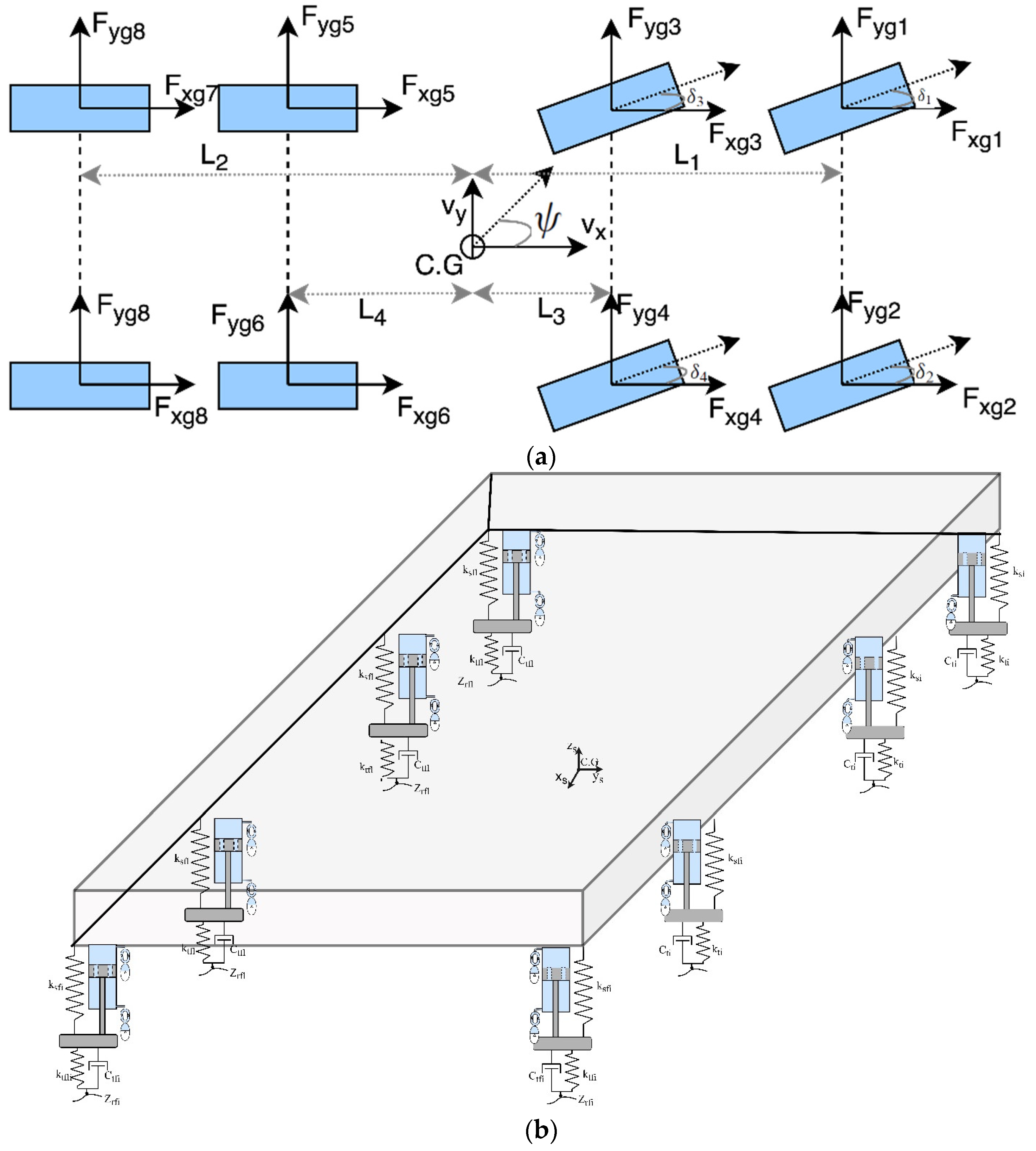
4.1. Vehicle Dynamic Truck Mathematical Model

In this section, a 22-DOF vehicle dynamic model was used to calculate the longitudinal, lateral, vertical, roll, pitch, and yaw motions of a truck. Hence, the longitudinal, lateral, and vertical tire ground forces are being considered for the modelling [43,44,45,46]. The dynamic equation of the longitudinal, lateral, and vertical motions of the truck are expressed as
m s V ˙ x + θ ˙ V z ψ ˙ V y = i = 1 8 F x s i
m s V ˙ y + ψ ˙ V x φ ˙ V z = i = 1 8 F y s i
m s V ˙ z + φ ˙ V y θ ˙ V x = i = 1 8 F z s i
Longitudinal force transferred to sprung mass
F x s i = F x g i c o s θ F z g i s i n θ m u i V ˙ x u i + θ ˙ V z u i ψ ˙ V y u i
Lateral force transferred to sprung mass
F y s i = F y g i c o s φ + F x g i s i n φ s i n θ + F z g i s i n φ c o s θ m u i V ˙ y u i + ψ ˙ V x u i φ ˙ V z u i
Vertical force transferred to sprung mass
F z s i = k s i z s d i + b s i z ˙ s d i ± F a r i + u i
F a r i = k a r i 2 d φ Z u r j 2 d
In this study, only the front two axles are steerable. So δ 5 8 = 0 Tire—ground force in longitudinal direction
F x g i = F x w i c o s δ i F y w i s i n δ i
Tire—ground force in lateral direction
F y g i = F x w i s i n δ i + F y w i c o s δ i
Tire—ground force in vertical direction
F z g i = k t i z t i
Equation of roll motion
I x φ ¨ = F z s 2 + F z s 4 + F z s 6 + F z s 8 F z s 1 F z s 3 F z s 5 F z s 7 d i = 1 8 F y s i . h r
Equation of pitch motion
I y θ ¨ = F z s 1 + F z s 2 L 1 F z s 3 + F z s 4 L 3 + F z s 5 + F z s 6 L 4 + F z s 7 + F z s 8 L 2 + i = 1 8 F x s i . h r
Equation of yaw motion
I z ψ ¨ = F x s 1 + F x s 3 + F x s 5 + F x s 7 d F x s 2 + F x s 4 + F x s 6 + F x s 8 d + F y s 1 + F y s 2 L 1 + F y s 3 + F y s 4 L 3 F y s 5 + F y s 6 L 4 F y s 7 + F y s 8 L 2
Equation of wheel rotation
I w i ω ˙ w i = R w i F x w i F z i f r T b i
Unsprung mass dynamic equation
m u s V ˙ z u i + φ ˙ V y u i θ ˙ V x u i = F x g i c o s φ s i n θ F y g i s i n φ + F z g i c o s φ c o s θ F z s i

4.2. Flow Rate through Hydraulic Control Valve

The equivalent orifice area of hydraulic servo valve ports of the pressure source, tank, compression, and rebound chamber side are calculated by the following relations:
Q s = Q c v r = C q ω x v P s s g n ( x v ) P ρ
Q t = Q c v c = C q ω x v P t s g n ( x v ) P ρ
The fractional spool position and velocity are calculated by the following second-order lag relations:
d 2 x v ( t ) d t 2 = 2 ω n ξ d x v d t + ω n 2 x v ( t ) = ω n 2 u ( t )
where ξ is the damping ratio and ω n is the natural frequency. If the control valve is saturated on the upper-end side, pressurized fluid from the source or pump is connected to the upper chamber or rebound chamber and the compression chamber is connected to the tank.
Q s = Q c v r Q c v c = Q t
If the valve is saturated on the lower-end side, pressurized fluid from the source is connected to the compression chamber and the rebound chamber is connected to the tank.
Q s = Q c v c Q c v r = Q t
Here, the spool valve dead-band is assumed as zero. The hysteresis of the valve here is defined as the widest separation between the flow rate through the control valve and control signal of the valve characteristics with decreasing and increasing input. This hysteresis effect can be expressed in terms of a compensated flow coefficient, valve hysteresis compensation, and input signal compensation parameters:
c v . c o m = k x v H ( x v ,   d f ) c v
The control valve damping ratio for the hysteresis effect is assumed here to be 0.80.

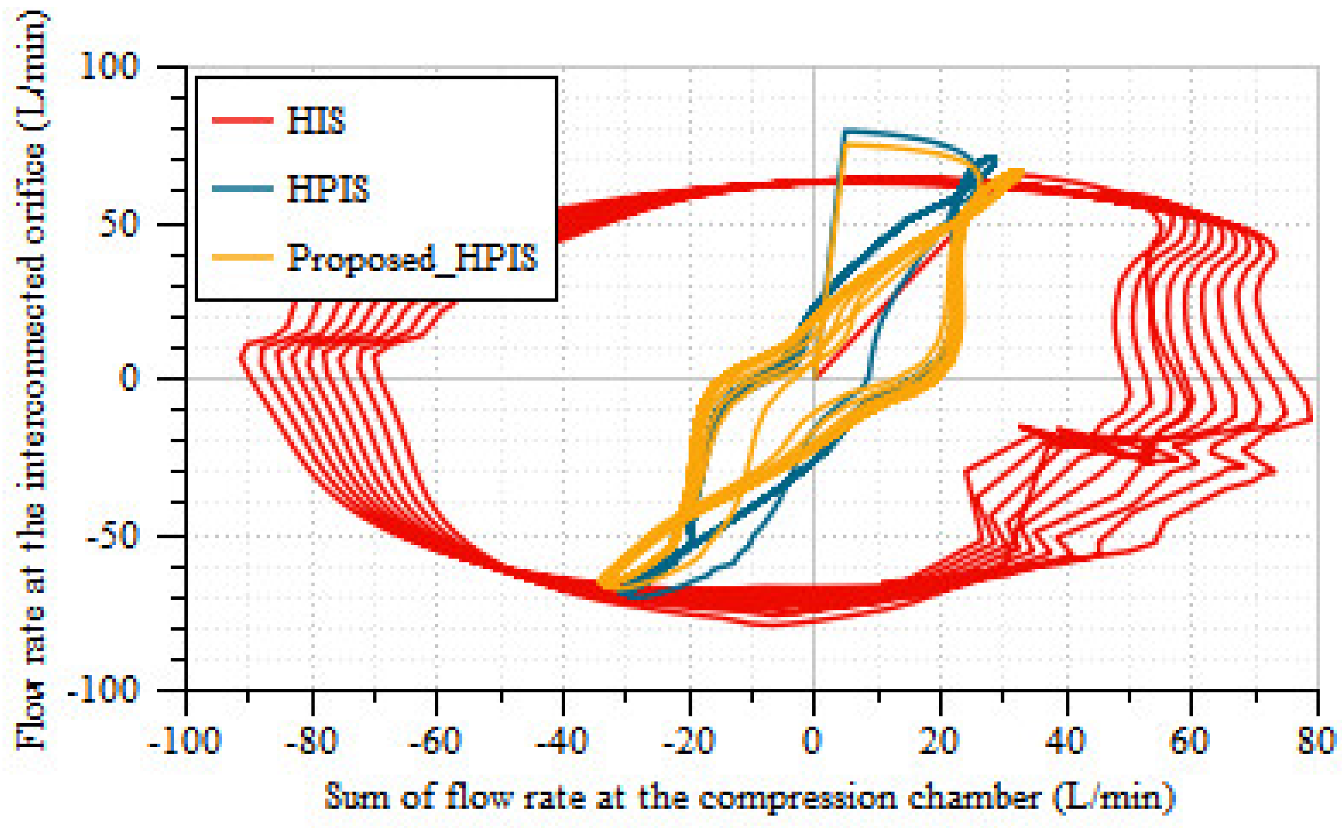
4.3. Interconnected Suspension

The equivalent orifice area of hydraulic servo valve ports of the pressure source, tank, compression, and rebound chamber side is calculated by the following relations. Each mode of the dampers and the respective piston positions along with them are illustrated in Figure 9.
Mode 1:
z > 0 , z ˙ > 0
In this mode, the piston is moving from equilibrium position to rebound stroke position and the fluid is discharged from the compression chamber to the rebound chamber through the piston orifice, hydro-pneumatic accumulators, and interconnected orifices. So, the damping mode of mode 1 is expressed as
Q P o L Q I n 1 + Q L U + Q I n 2 + Q L L = z ˙ L A c A r
Q P o R + Q I n 1 + Q R U Q I n 2 + Q R L = z ˙ R A c A r
Mode 2:
z > 0 , z ˙ < 0
Q P o L + Q I n 1 Q L L Q I n 2 = z ˙ L A c A r
Q P o R Q I n 1 + Q I n 2 Q R L = z ˙ R A c A r
Mode 3:
z < 0 , z ˙ < 0
Q P o L + Q I n 1 Q L U Q I n 2 Q L L = z ˙ L A c A r
Q P o R Q I n 1 Q R U + Q I n 2 Q R L = z ˙ R A c A r
Mode 4: z < 0 , z ˙ > 0
Q P o L Q I n 1 + Q I n 2 + Q L L = z ˙ L A c A r
Q P o R + Q I n 1 Q I n 2 + Q R L = z ˙ R A c A r
Here, Q L U , Q L L , Q R U and Q R L are indicated as the flow rate from the chamber to the left upper, lower, right upper, and lower accumulators, respectively. In the proposed-HPIS, the flow rates of the interconnected system mode 1 is Q L U = − Q c v 1 ; Q L L = − Q c v 3 ; Q R U = − Q c v 5 ; Q R L = − Q c v 7 : for mode 2 Q L U = Q R U = 0; Q L U = Q c v 4 ; Q R U = Q c v 8 : for mode 3 Q L U = − Q c v 2 ; Q L U = − Q c v 4 ; Q R U = − Q c v 6 ; Q R U = − Q c v 8 : for mode 4 Q L U = Q R U = 0; Q L U = − Q c v 3 ; Q R U = − Q c v 7 . And For the HIS system the Q L U , Q L L , Q R U and Q R L are equal to zero.
Here Q P o L and Q P o R are the flow rates through the left and right damper piston orifice, respectively.
Q I n 1 = C q A 2 P 1 P 4 ρ . ρ ρ ( 0 ) s i g n ( P 1 P 4 )
Q I n 2 = C q A 2 P 2 P 3 ρ . ρ ρ ( 0 ) s i g n ( P 2 P 3 )
Q P o L = C q A 2 P 1 P 2 ρ . ρ ρ ( 0 ) s i g n ( P 1 P 2 )
Q P o R = C q A 2 P 3 P 4 ρ . ρ ρ ( 0 ) s i g n ( P 3 P 4 )

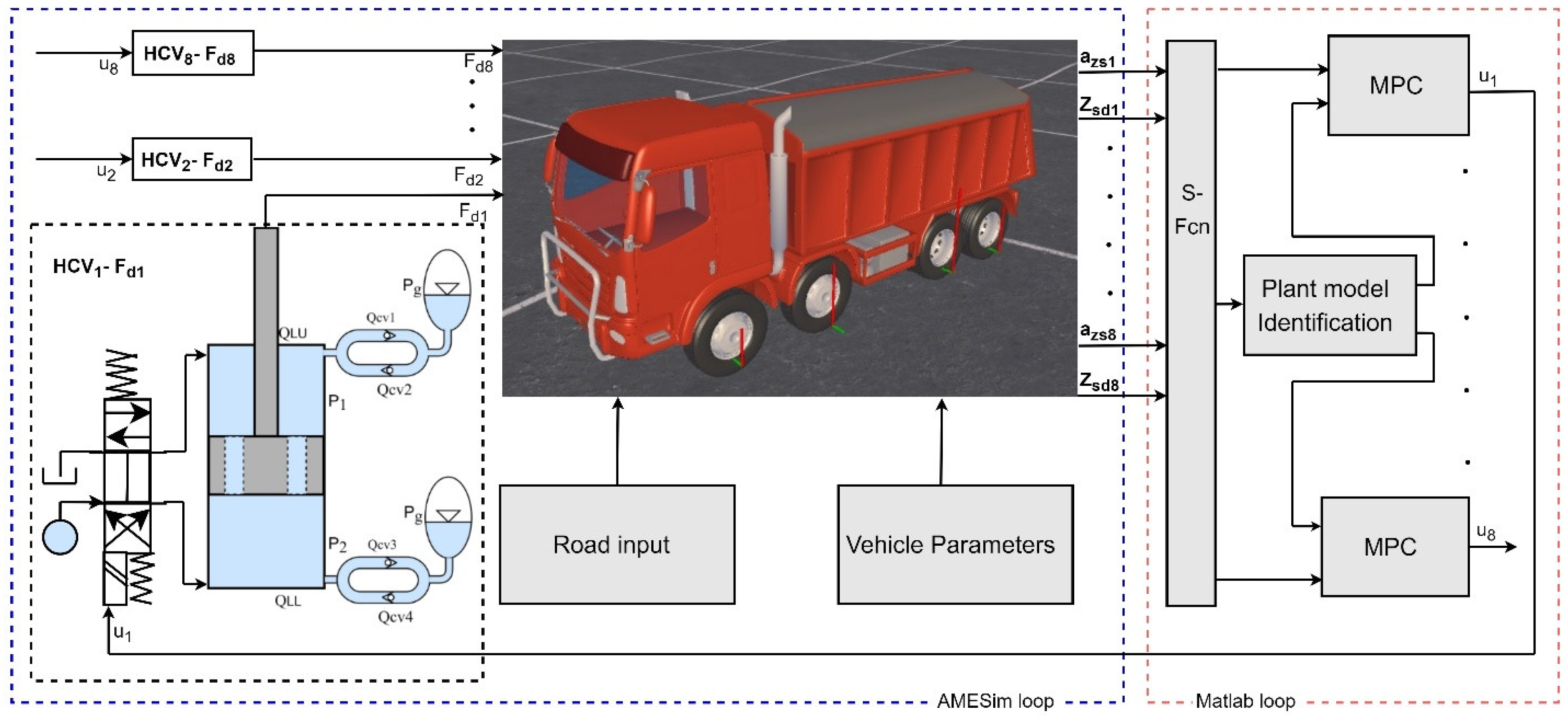
5. Identification, Control, and Co-Simulation

5.1. Co-Simulation

The overall co-simulation block diagram of the proposed active HPD suspension with MPC control strategy and plant identification. The proposed HPD and hydraulic control valve with four-axle truck suspension are modelled in LMS/AMESim software. The 22DOF comprises vehicle body longitudinal, lateral, vertical, roll, pitch, and yaw motions. Similarly, each of the wheels have both rotational and vertical movements, represented in Figure 10a,b. Then, the model was exported to Matlab/Simulink environment as S-functions for the co-simulation, which is also a time-discrete block as shown in Figure 11. In this study, Matlab was used for controlling the hydraulic control valve by implementing a MPC/PID in Matlab environment, whereas the AMESim was used for complete non-linear truck simulation.

5.2. Identification

The hydraulic control-valve-controlled, hydro-pneumatic-based active suspension integrated linear discrete mathematical model is required for the MPC controller design. For the MPC design, the state plant was identified through a simple identification method and the respective input and output of the model were obtained from the AMESim nonlinear simulation. The identification was determined using Matlab, which adopted state space methods for simulating the mathematical model. The identified system has a fitness of 94.45%. The estimated model is expressed as
x ˙ k + 1 = A 1 x ( k ) + B 1 u ( k ) + K e k
y k = C 1 x ( k ) + D 1 u ( k ) + e k
The identified state space model is sufficiently accurate to mimic the dynamic response of the truck model according to fit response. The estimated model is used for the MPC controller design which is shown in Figure 11.

5.3. Controller Design

With respect to the proposed HPD force, with low damping force F d i = F d m i n   i , road holding is prioritized, whereas with high damper force F d i = F d m a x   i , comfort becomes stronger. The proposed damping force of the active suspension scheme is defined with additional details to deal with the MPC method.
F d m i n   i z ˙ s d i k + i k F d i k + i k F d m a x   i z ˙ s d i k + i k
And the controller constraints are
F d m i n   i F d m a x   i 2 u i k + i k F d m a x   i F d m i n   i 2
whereas the nominal damping force of the hydro-pneumatic system is F d n o m   i = F d m i n   i + F d m a x   i 2 . F d i k + i k denotes the k sample of the i t h damper force and z ˙ s d i k + i k denotes the k sample of i t h suspension deflection velocity.
At each time instant ( k ), the measured output acceleration is sampled to calculate the plant output at time ( k + 1 ) to optimize the function ( J k ) , which is expressed as
J k = i = 1 P q . y ^ k + i k R k + i k 2 + i = 0 M 1 r . u i k + i k 2
In the minimization of the quadratic cost function, MPC provides the optimal ( u i ) until the ( k + 1 ) time interval, when the control will be reiterated. In addition, measured and unknown disturbances affect the estimation of output acceleration. Moreover, each term in the weights will minimize J k , and suppress the system response as described by Equation (57). To obtain the robust enactments, except for the linear model used within MPC and constrained set on y ^ k + i k ,   R k + i k ,   u i k + i k , the horizons and weighing function also influence the controller performances. And hence, several MPC tuning methods were investigated to obtain appropriate values for improving the performance of the controller. MPC tuning has a primary effect on exploratory parameters without precise calculation methods for the tuning of each parameter. Yuan and Garriga [47,48,49] listed optimizing functions for horizons and weights. In the prediction horizon ( P ), if the numerical value increases, the system response will be stable and the settling time will be longer. If the control horizon value is high, the controller will be robust and requires larger computational power. The error weighing output function ( q ) is adjusted using the manipulated variable ( r ) by controlling the output. When the small change in ( r ) is penalized, the aggression of the controller will be reduced.

5.4. PID Controller

The MPC is compared with a common PID controller, hence, the PID controller is implemented using the following relations [50,51];
e k = S P k P V k
u k = K p e k + u i k 1 + K p T i e k + e ( k 1 ) 2 T K p T d T ( P V k P V ( k 1 ) )

6. Results and Discussion

In this section, two different kinds of approaches are used to evaluate the effectiveness of the HPD such as 1. The active suspension system study is performed to analyze the effectiveness of the HPD when it is connected with the control valve and the additional fluid pressure source. The proposed MPC and PID control scheme applied to the 22DOF truck suspension system shown in Figure 11. The performance of the PID- and MPC-controlled hydro-pneumatic active suspension system is compared against the proposed passive suspension. The corresponding results are provided to verify the adaptability and ability of HPD when the damping values are updated. 2. A roll interconnected suspension study of this paper is used to assess the proposed HPD characteristics, when it is interconnected. The performance of the proposed HPIS is compared with the existing HPIS and HIS to identify the variation in responses.
 Case 1: 
 
To verify the active suspension effectiveness of the proposed HPD, the band limited white noise value of 256 × 106 with the sample time of 0.01 s is used. According to ISO-8608, road unevenness was mathematically calculated with respect to vehicle longitudinal velocity and roughness grade [52], which can be expressed as
z ˙ r = 2 π n 00 z r V x + 2 π n 0 w ( t ) G q n 0 V x
where G q n 0 represents the road roughness level, w ( t ) is the gauss white noise, and n 00 and n 0 are the cut-off and reference spatial frequency, respectively. Figure 12 and Figure 13 show the sprung mass acceleration of time and frequency responses, respectively. Here, the improvement of the MPC controlled system is 40% greater than the proposed passive suspension. The sprung mass acceleration is set with much greater weight than the other controller weights to enhance the ride comfort performance of the truck with the MPC design. The PID controller is also tuned for the same performance index [53,54]. Hence, the improvement of the sprung mass acceleration is much higher than conventional systems. However, the new active HPD can achieve different damping by adjusting the hydraulic control valves.
The additional supply and discharge from the chambers of HPD through control valve creates a quick variation in the chamber pressure. Thus, the flow through the check valves is reduced. At the same time, in the passive HPD, the pressure variation is as mentioned in Figure 8. Therefore, the active HPD is more efficient than the proposed passive suspension systems. Figure 14 and Figure 15 depict the time and frequency responses of the suspension velocity of the truck, respectively. Although the suspension deflection of MPC is decreased 22% more than the passive suspension, there is also a significant increase in the deflection velocity of the PID and MPC controlled systems than those in the passive suspension, as shown in Table 2.
 Case 2: 
 
In this study, the left and right suspension of each axle are interconnected separately through the orifice. Therefore, the anti-roll bar is not used in this study. The standalone HIS, HPIS, and proposed-HPIS depict the passive or separate, hydraulically interconnected suspension, hydro-pneumatic interconnected suspension, and proposed hydro-pneumatic interconnected suspension, respectively [55]. The sinusoidal signal as expressed in Equation (60) is given as an input to the vehicle wheels with various phase shifts. For the first axle right, second axle left, third axle right, and fourth axle left, respectively, the sine inputs are given with the phase shift of 90 degrees and for remaining wheels, the input is given without any phase shift.
z r t = A . sin ( t + φ p )
Here, z r denotes the road vertical displacement, A refers to the amplitude, is the angular velocity, and φ p is phase shift. The time and frequency responses of V ˙ x ,   V ˙ y ,   V ˙ z , φ ¨ , θ ¨ ,   ψ ¨ are provided to verify the performance improvement/deterioration of the proposed system. The plot of the sum of the flow rate with respect to the interconnected orifice and piston orifice are provided to justify the proposed HPD ability, when it is interconnected.
Figure 16a–c depicts the time response of truck body longitudinal, lateral, and vertical accelerations, respectively. Figure 16d–f depicts the frequency response of the truck body longitudinal, lateral, and vertical accelerations, respectively. It is clearly indicated that longitudinal acceleration of all the systems were very similar. The maximum V ˙ y values of 0.0077 m/s2 are produced by the standalone system and HPIS produces a low RMS acceleration value of 0.0052 m/s2, which is shown in the time and frequency response in Figure 16b,e. When comparing the maximum vertical acceleration of both HIS and standalone systems, the latter one provides better results, which are shown in Figure 16c,f. In the interconnected system, the hydraulic fluid flows to the low-pressure side through interconnected orifices. By establishing the flow of hydraulic fluid to the low-pressure side, the damping constant of the IS will be reduced more than standalone system. And due to the accumulator pre-charge gas pressure, the maintained pressure of hydro-pneumatic systems will be higher than the HIS. Therefore, the change of flow rate of both HPIS through interconnected orifices will be lesser than HIS. Higher damping will be maintained in both HPIS systems. And, hence, in both HPIS systems, the vertical acceleration RMS values are less than the HIS.
Figure 17a–c depicts the time response of the truck body roll, pitch, and yaw acceleration, respectively. Figure 17d–f depicts the frequency response of truck body roll, pitch, and yaw acceleration, respectively. It is identified that the proposed HPIS RMS roll acceleration value is 0.2689 m/s2, which is better than the HIS and standalone hydro-pneumatic systems. This is because the flow through the interconnected orifice of HIS suspension will be significantly higher than HPIS. From the Figure 17b,e, for the pitch acceleration of time and frequency responses, the roll interconnected suspension system is not influencing the pitch motions of a vehicle. The yaw acceleration of standalone system is higher than all the systems, which are shown in Figure 17c,f. The HPIS is providing a lower RMS value of 0.6323 rad/s2 and when compared to the standalone system, 63% were improved as shown in Table 3.
Figure 18 shows the plot of the sum of the flow rate to the compression chamber and interconnected orifice flow rate of HIS, HPIS, and the proposed damper HPIS. Here, the sum of the flow rate HIS denotes flow from the chamber through the piston orifice and interconnected orifice. And the sum of the flow rate of HPIS denotes the flow rate from the chamber, hydro-pneumatic accumulator, and interconnected orifice. The flow through the interconnected orifice of both HPIS systems is very similar in characteristics during the flow in and out with respect to the total flow rate of the compression/rebound chambers of the damper (i.e., less width). But the HIS system interconnected orifice flow rate has the asymmetric characteristics with respect to the sum of the flow rate. Due to this characteristic, the performance of the lateral acceleration of both HPIS is significantly better than HIS.
Figure 19 depicts the flow rate of the piston orifice with respect to the sum of the flow rate of the compression chamber. Here, the proposed HPIS and HPIS characteristics are very similar during filling and discharging of the chamber (i.e., a comparatively lower hysteresis effect). In the HPIS system, a considerable amount of fluid flows to the hydro-pneumatic accumulator, and hence, the slope of the HIS is lower than the HPIS systems. Therefore, the flow through the piston orifice of HIS is typically high, and thus the vertical damping of HIS is reduced. Therefore, the vertical and yaw acceleration of HIS is higher than the HPIS. In addition to this, both the HPIS characteristics are very similar in Figure 18 and Figure 19. It is evident that the proposed pressure-independent, velocity-dependent hydro-pneumatic system is able to perform in interconnected systems without affecting the existing HPIS characteristics.

7. Conclusions

The proposed work describes and proposes a novel hydro-pneumatic chamber pressure-independent, velocity-dependent damper to suppress vehicle vibration effectively by reducing the F-V hysteresis effect. For the numerical investigation, the corresponding modeling of HPD and truck with the essential parameters was considered. Overall, the following conclusions can be drawn.
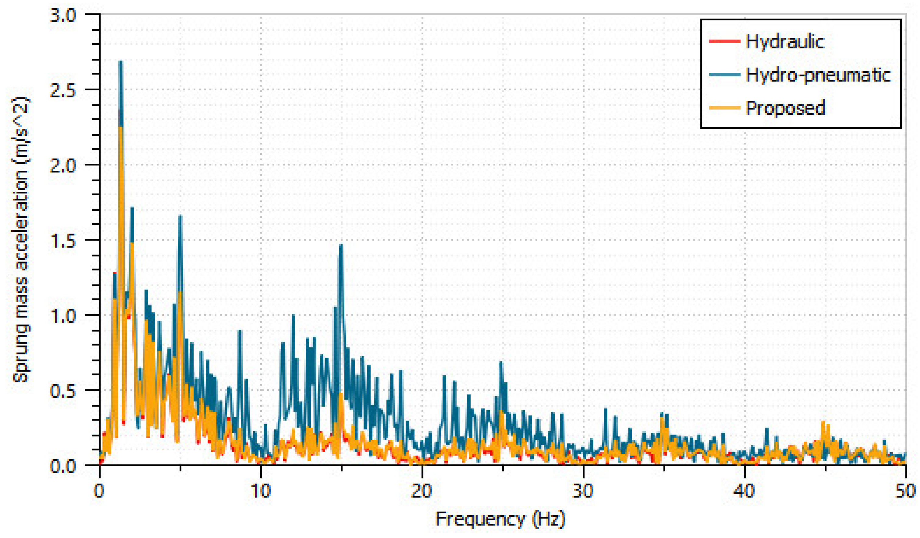
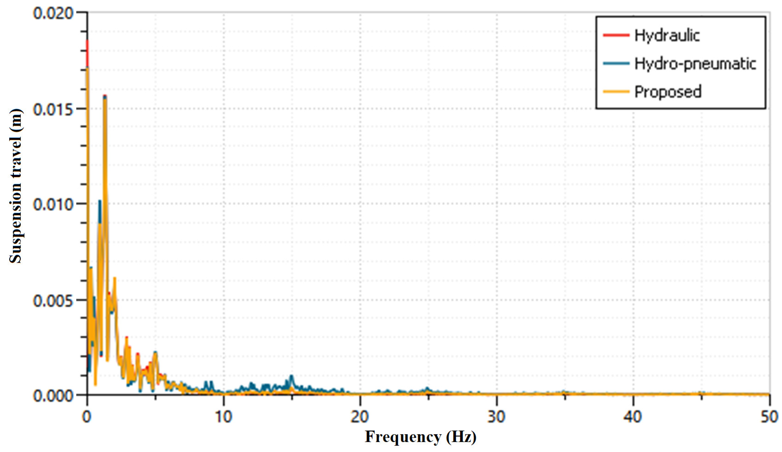
  • From the passive systems analysis, the sprung mass acceleration of 33.64% is suppressed by the proposed HPD better than the well-known existing HPD. Also, rattle space and tire load performance improvement of the proposed HPD is more significant than the hydraulic damper.
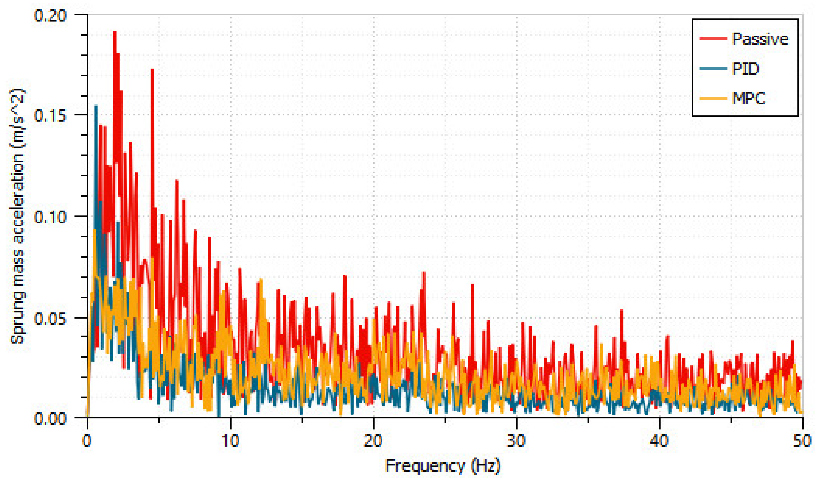
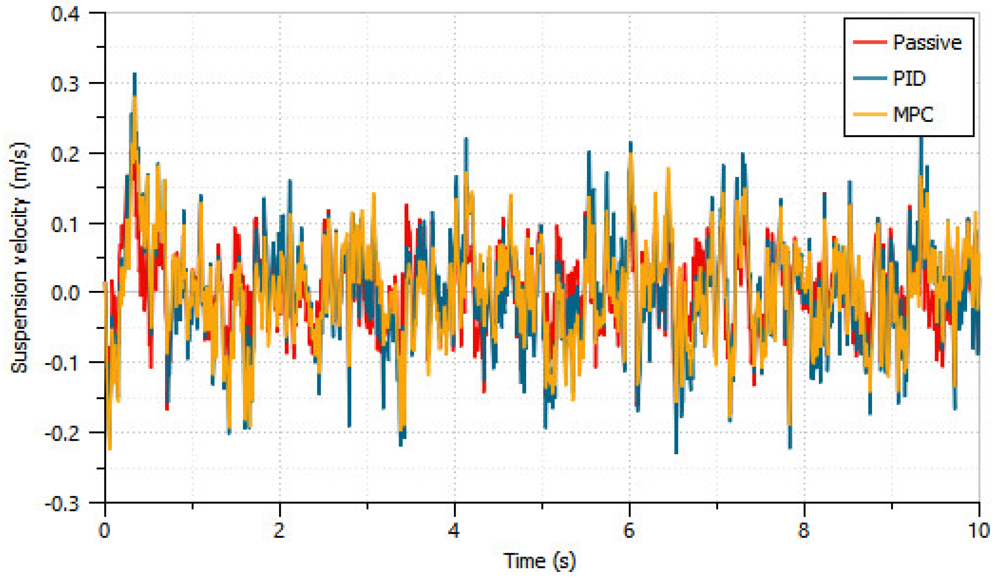
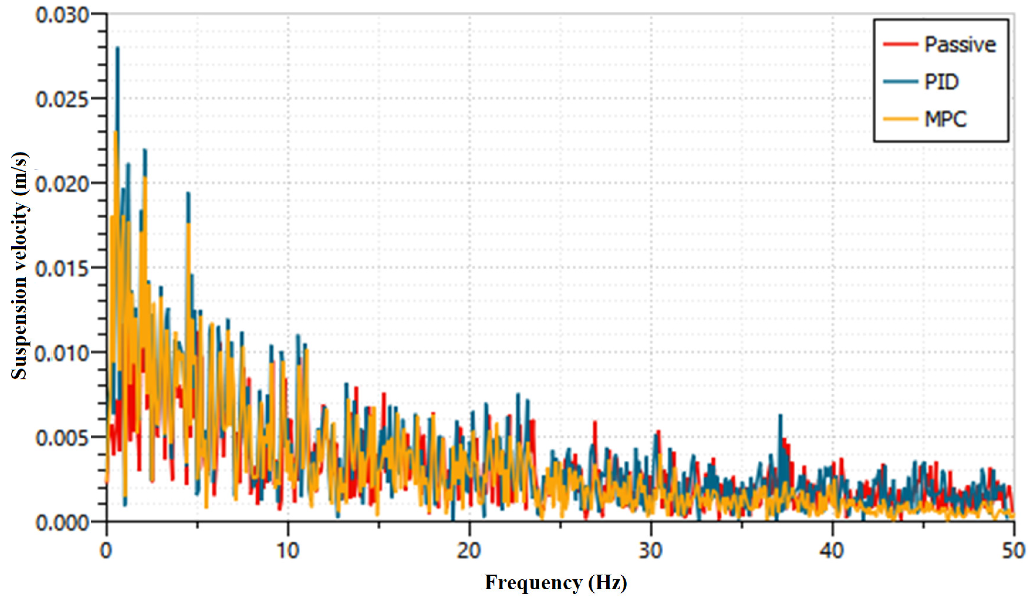
  • From the active suspension investigation, simply designed MPC and PID mitigate the sprung mass acceleration of the heavy truck of 39.8% and 50.4%, respectively. In addition, the conflict parameter of suspension deflection of the standalone active system was improved to 22% more than the passive HPD vehicle. It is evident that the proposed active HPD is capable of working in a truck active suspension scheme.
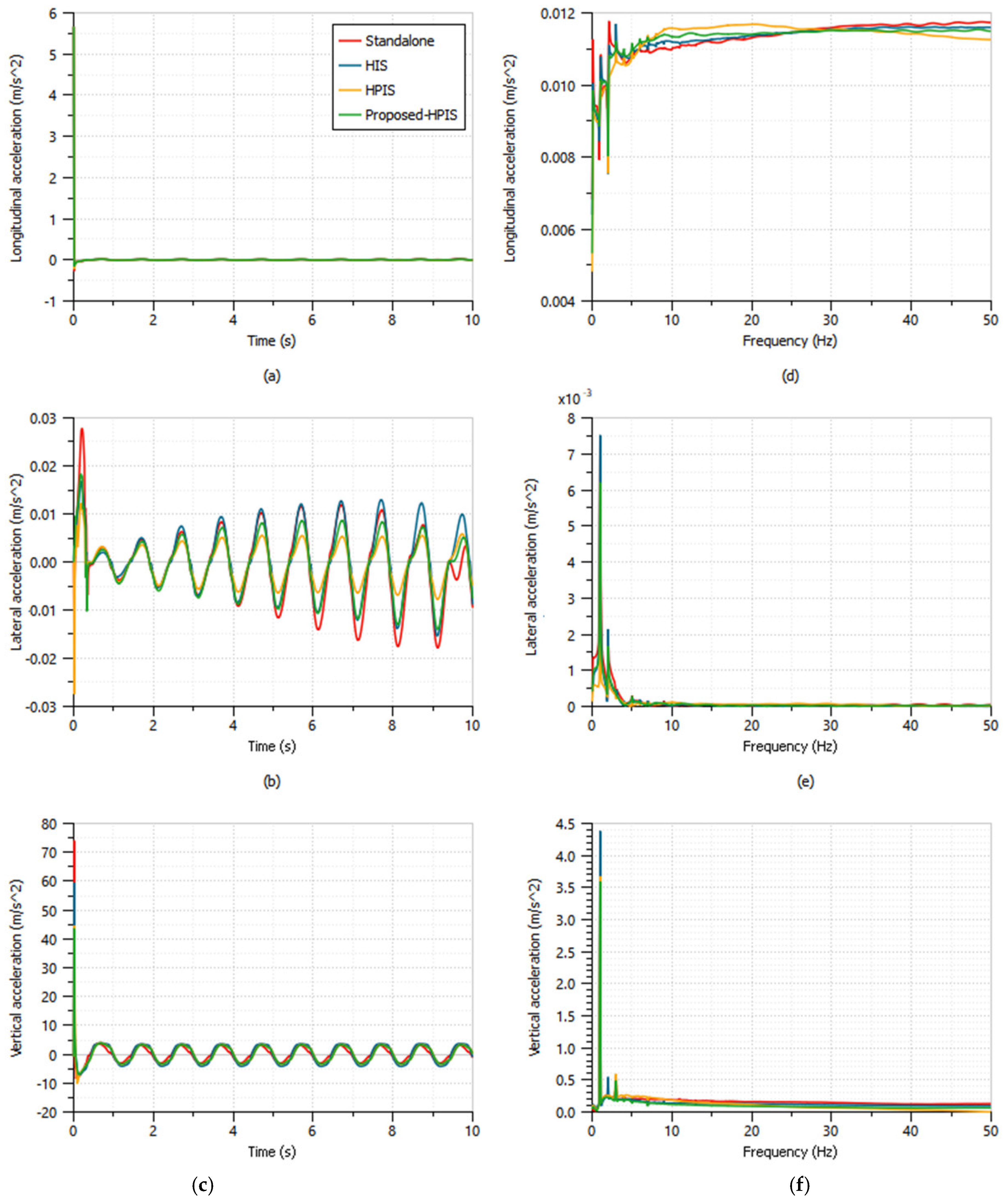
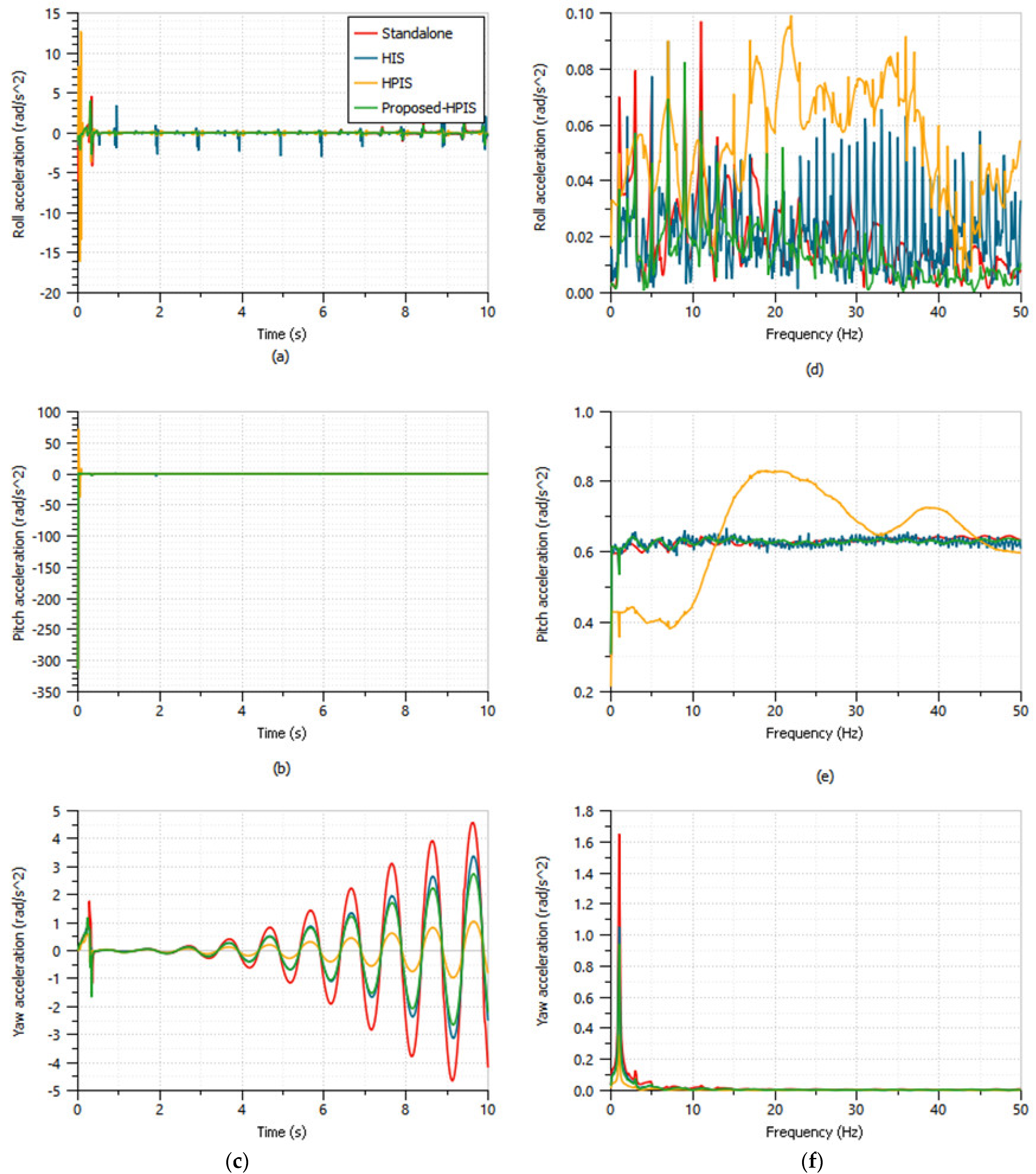
  • Moreover, from the interconnected investigation, it was illustrated that there is a marginal improvement in heave and pitch acceleration of the proposed HPIS system over existing HIS and HPIS. In addition, roll acceleration is improved to 70.1% more than the existing HPIS with the compromise of 62.4% in yaw acceleration. Hence, the proposed HPD can be implemented into practical scenarios.

Author Contributions

Conceptualization, M.T. and T.J.; methodology, M.T. and T.J.; software, M.T. and T.J.; validation, M.T. and T.J.; formal analysis, M.T. and T.J.; investigation, M.T. and T.J.; resources, M.T. and T.J.; writing—original draft preparation, M.T. and T.J.; project administration, M.T. and T.J.; funding acquisition, M.T. and T.J. All authors have read and agreed to the published version of the manuscript.

Funding

This research received no external funding.

Institutional Review Board Statement

Not applicable.

Informed Consent Statement

Not applicable.

Data Availability Statement

The data presented in this study are available in the article.

Acknowledgments

The authors extend their appreciation to Department of Mechanical Engineering, National Institute of Technology, Puducherry, India for providing consent to use the research facilities.

Conflicts of Interest

The authors declare no conflict of interest.

Abbreviations

Simulation Parameters
P a 5.3MPa
v o l 0 50cm3
d Q P o i d t 12L/min
P c r a c k i 0.5MPa
g r a d i 1L/min/bar
P L L ,   P L U 7MPa
m s 16,000kg
m u s 500kg
c u s 100,000Ns/m
k s i 74,000 (F), 82,000 (R)N/m
k u s 400,000N/m
k a r i 80,000Nm/rad
2 d 2160mm
L 1 2900mm
L 2 3200mm
L 3 1170mm
L 4 1820mm
Nomenclature
ParametersUnitsDescription
A c , A r m2cross sectional area of piston in compression and rebound chamber side
P 1 , P 2 MParebound and compression chamber pressure
P g c , P g r MPaGas pressure of upper and lower accumulator
V g c , V g r m3Volume of the gas in compression and rebound chamber side accumulator
V a c , V a r m3Volume of the accumulator in compression and rebound chamber side
P s a t i MPa i t h check valve saturation pressure
P c r a c k i MPa i t h check valve cracking pressure
x v i %Fractional valve opening of the valve
P c v i MPaPressure drop of i t h check valve
Q s ,   Q t L/minFlow rate from source and tank orifice
d h mHydraulic diameter of orifice
P w mWet perimeter of orifice
A m2cross sectional area of orifice
C q -flow co-efficient
λ -flow number
ϑ m2/skinematic viscosity
λ c r i t -critical flow number
ρ kg/m3density
ω m2Valve area gradient
F x g i ,   F y g i , F z g i NLongitudinal, lateral and vertical forces of i t h tire-ground contact forces
F x s i , F y s i , F z s i NLongitudinal, lateral and vertical force transferred to the sprung mass at i t h suspension mounting
F x w i , F y w i , F z w i N i t h longitudinal, lateral and vertical tire force
I w i kg. m2Moment of inertia of the wheel
F z i NVertical of load of wheel
f r -Rolling resistance
R w i mWheel radius
T b i NmBraking torque
δ i radWheel steer angle
k t i , c t i N/m, Ns/m i t h tire stiffness and damping constant
z t i m i t h tire deflection
V z g i m/svertical velocity of i t h tire-ground contact forces
M s kgTruck sprung mass
V x , V y ,   V z m/sLongitudinal, lateral and vertical velocity
z s d i , z ˙ s d i m, m/sRelative displacement and velocity of sprung and unsprung mass at i t h suspension mounting

References

  1. Quaglia, G.; Sorli, M. Air Suspension Dimensionless Analysis and Design Procedure. Veh. Syst. Dyn. 2003, 35, 443–475. [Google Scholar] [CrossRef]
  2. Nieto, A.J.; Morales, A.L.; González, A.; Chicharro, J.M.; Pintado, P. An Analytical Model of Pneumatic Suspensions Based on an Experimental Characterization. J. Sound Vib. 2008, 313, 290–307. [Google Scholar] [CrossRef]
  3. Porumamilla, H.; Kelkar, A.G.; Vogel, J.M. Modeling and Verification of an Innovative Active Pneumatic Vibration Isolation System. J. Dyn. Syst. Meas. Control 2008, 130, 031001. [Google Scholar] [CrossRef]
  4. Sathishkumar, P.; Wang, R.; Yang, L.; Thiyagarajan, J. Trajectory Control for Tire Burst Vehicle Using the Standalone and Roll Interconnected Active Suspensions with Safety-Comfort Control Strategy. Mech. Syst. Signal Process. 2020, 142, 106776. [Google Scholar] [CrossRef]
  5. Yin, Z.; Khajepour, A.; Cao, D.; Ebrahimi, B.; Guo, K. A New Pneumatic Suspension System with Independent Stiffness and Ride Height Tuning Capabilities. Veh. Syst. Dyn. 2012, 50, 1735–1746. [Google Scholar] [CrossRef]
  6. Nieto, A.J.; Morales, A.L.; Chicharro, J.M.; Pintado, P. An Adaptive Pneumatic Suspension System for Improving Ride Comfort and Handling. JVC J. Vib. Control 2016, 22, 1492–1503. [Google Scholar] [CrossRef]
  7. Chen, Y.; Peterson, A.W.; Ahmadian, M. Achieving Anti-Roll Bar Effect through Air Management in Commercial Vehicle Pneumatic Suspensions. Veh. Syst. Dyn 2019, 57, 1775–1794. [Google Scholar] [CrossRef]
  8. Chen, Y.; Hou, Y.; Peterson, A.; Ahmadian, M. Failure Mode and Effects Analysis of Dual Levelling Valve Airspring Suspensions on Truck Dynamics. Veh. Syst. Dyn. 2019, 57, 617–635. [Google Scholar] [CrossRef]
  9. Bauer, W. Hydropneumatic Suspension Systems; Springer: Berlin/Heidelberg, Germany, 2011; ISBN 978-3-642-15146-0. [Google Scholar]
  10. Shi, J.W.; Li, X.W.; Zhang, J.W. Feedback Linearization and Sliding Mode Control for Active Hydropneumatic Suspension of a Special-Purpose Vehicle. Proc. Inst. Mech. Eng. Part D J. Automob. Eng. 2010, 224, 41–53. [Google Scholar] [CrossRef]
  11. Yin, C.; Zhai, X.; Sun, X.; Wang, S.; Wong, P.K. Design and Performance Research of a Hydro-Pneumatic Suspension with Variable Damping and Stiffness Characteristics. J. Mech. Sci. Technol. 2022, 36, 4913–4923. [Google Scholar] [CrossRef]
  12. Calvo, J.A.; López-Boada, B.; Román, J.L.S.; Gauchía, A. Influence of a Shock Absorber Model on Vehicle Dynamic Simulation. Proc. Inst. Mech. Eng. Part D J. Automob. Eng. 2009, 223, 189–202. [Google Scholar] [CrossRef]
  13. Liu, Y.; Zhang, J. Nonlinear Dynamic Responses of Twin-Tube Hydraulic Shock Absorber. Mech. Res. Commun. 2002, 29, 359–365. [Google Scholar] [CrossRef]
  14. Łuczko, J.; Ferdek, U. Non-Linear Analysis of a Quarter-Car Model with Stroke-Dependent Twin-Tube Shock Absorber. Mech. Syst. Signal Process. 2019, 115, 450–468. [Google Scholar] [CrossRef]
  15. Tan, B.; Lin, X.; Zhang, B.; Zhang, N.; Qi, H.; Zheng, M. Nonlinear Modeling and Experimental Characterization of Hydraulically Interconnected Suspension with Shim Pack and Gas-Oil Emulsion. Mech. Syst. Signal Process. 2023, 182, 109554. [Google Scholar] [CrossRef]
  16. Zhang, Y.; Zhang, X.; Zhan, M.; Guo, K. Study on a Novel Hydraulic Pumping Regenerative Suspension for Vehicles. J. Frankl. Inst. 2015, 352, 485–499. [Google Scholar] [CrossRef]
  17. Westhuizen, S.F.; Els, P.S. Comparison of Different Gas Models to Calculate the Spring Force of a Hydropneumatic Suspension. J. Terramechanics 2015, 57, 41–59. [Google Scholar] [CrossRef]
  18. Lin, D.; Yang, F.; Li, R. Experimental Modelling and Analysis of Compact Hydro-Pneumatic Interconnected Suspension Strut Considering Pneumatic Thermodynamics and Hydraulic Inertial Properties. Mech. Syst. Signal Process. 2022, 172, 108988. [Google Scholar] [CrossRef]
  19. Spelta, C.; Previdi, F.; Savaresi, S.M.; Bolzern, P.; Cutini, M.; Bisaglia, C.; Bertinotti, S.A. Performance Analysis of Semi-Active Suspensions with Control of Variable Damping and Stiffness. Veh. Syst. Dyn. 2011, 49, 237–256. [Google Scholar] [CrossRef]
  20. Abd-EI-Tawwab, A.M. Twin Accumulator Semi Active Suspension System with Preview Control. J. Low Freq. Noise Vib. Act. Control 2008, 26, 283–294. [Google Scholar] [CrossRef]
  21. Li, Z.; Wang, Y.; Du, H.; Hu, Z. Modelling and Analysis of Full-Vehicle Hydro-Pneumatic Suspension System Considering Real-Gas Polytropic Process. Mech. Syst. Signal Process. 2022, 165, 108406. [Google Scholar] [CrossRef]
  22. Sang, Z.; Dong, M.; Gu, L. Numerical Analysis of a Dual-Chamber Hydro-Pneumatic Suspension Using Nonlinear Vibration Theory and Fractional Calculus. Adv. Mech. Eng. 2017, 9, 1–13. [Google Scholar] [CrossRef]
  23. Zhao, Y.; Xu, H.; Deng, Y.; Wang, Q. Multi-Objective Optimization for Ride Comfort of Hydro-Pneumatic Suspension Vehicles with Mechanical Elastic Wheel. Proc. Inst. Mech. Eng. Part D J. Automob. Eng. 2018, 233, 2714–2728. [Google Scholar] [CrossRef]
  24. Smith, W.A.; Zhang, N.; Jeyakumaran, J. Hydraulically Interconnected Vehicle Suspension: Theoretical and Experimental Ride Analysis. Veh. Syst. Dyn. 2010, 48, 41–64. [Google Scholar] [CrossRef]
  25. Zhang, N.; Smith, W.A.; Jeyakumaran, J. Hydraulically Interconnected Vehicle Suspension: Background and Modelling. Veh. Syst. Dyn. 2010, 48, 17–40. [Google Scholar] [CrossRef]
  26. Ding, F.; Zhang, N.; Liu, J.; Han, X. Dynamics Analysis and Design Methodology of Roll-Resistant Hydraulically Interconnected Suspensions for Tri-Axle Straight Trucks. J. Frankl. Inst. 2016, 353, 4620–4651. [Google Scholar] [CrossRef]
  27. Ding, F.; Han, X.; Zhang, N.; Luo, Z. Characteristic Analysis of Pitch-Resistant Hydraulically Interconnected Suspensions for Two-Axle Vehicles. J. Vib. Control 2015, 21, 3167–3188. [Google Scholar] [CrossRef]
  28. Xu, G.; Zhang, N.; Roser, H.M. Roll and Pitch Independently Tuned Interconnected Suspension: Modelling and Dynamic Analysis. Veh. Syst. Dyn. 2015, 53, 1830–1849. [Google Scholar] [CrossRef]
  29. Xu, G.; Zhang, N. Characteristic Analysis of Roll and Pitch Independently Controlled Hydraulically Interconnected Suspension. SAE Int. J. Commer. Veh 2014, 7, 170–175. [Google Scholar] [CrossRef]
  30. Zhu, H.; Yang, J.; Zhang, Y. Modeling and Optimization for Pneumatically Pitch-Interconnected Suspensions of a Vehicle. J. Sound Vib. 2018, 432, 290–309. [Google Scholar] [CrossRef]
  31. Tang, C.; Goodarzi, A.; Khajepour, A. A Novel Integrated Suspension Tilting System for Narrow Urban Vehicles. Proc. Inst. Mech. Eng. Part D J. Automob. Eng. 2018, 232, 1970–1981. [Google Scholar] [CrossRef]
  32. Cao, D.; Rakheja, S.; Su, C.Y. Dynamic Analyses of Roll Plane Interconnected Hydro-Pneumatic Suspension Systems. Int. J. Veh. Des. 2015, 47, 51. [Google Scholar] [CrossRef]
  33. Palanisamy, S.; Thangaraj, M.; Elsheikh, A.H. A review of flexible printed sensors for automotive infotainment systems. Arch. Civ. Mech. Eng. 2023, 23, 67. [Google Scholar] [CrossRef]
  34. Palanisamy, S.; Thangaraj, M. Fabrication and Performance Evolution of AgNP Interdigitated Electrode Touch Sensor for Automotive Infotainment. Sensors 2021, 21, 7961. [Google Scholar] [CrossRef]
  35. Palanisamy, S.; Thangaraj, M.; Moiduddin, K.; Al-Ahmari, A.M. Fabrication and Performance Analysis of 3D Inkjet Flexible Printed Touch Sensor Based on AgNP Electrode for Infotainment Display. Coatings 2022, 12, 416. [Google Scholar] [CrossRef]
  36. Cao, D.; Rakheja, S.; Su, C.Y. Roll- and Pitch-Plane-Coupled Hydro-Pneumatic Suspension. Part 2: Dynamic Response Analyses. Veh. Syst. Dyn. 2010, 48, 507–528. [Google Scholar] [CrossRef]
  37. Lallart, M.; Li, K.; Yang, Z.; Wang, W. System-Level Modeling of Nonlinear Hysteretic Piezoelectric Actuators in Quasi-Static Operations. Mech. Syst. Signal Process 2019, 116, 985–996. [Google Scholar] [CrossRef]
  38. Palomares, E.; Nieto, A.J.; Morales, A.L.; Chicharro, J.M.; Pintado, P. Dynamic Behaviour of Pneumatic Linear Actuators. Mechatronics 2017, 45, 37–48. [Google Scholar] [CrossRef]
  39. GP, S.; MM, K. A Contemporary Adaptive Air Suspension Using LQR Control for Passenger Vehicles. ISA Trans. 2019, 93, 244–254. [Google Scholar] [CrossRef]
  40. Yin, Y.; Rakheja, S.; Yang, J.; Boileau, P. Characterization of a Hydro-Pneumatic Suspension Strut with Gas-Oil Emulsion. Mech. Syst. Signal Process. 2018, 106, 319–333. [Google Scholar] [CrossRef]
  41. Graczykowski, C.; Pawłowski, P. Exact Physical Model of Magnetorheological Damper. Appl. Math. Model. 2017, 47, 400–424. [Google Scholar] [CrossRef]
  42. Liu, S.; Zhou, H.; Luo, X.; Xiao, J. Adaptive Sliding Fault Tolerant Control for Nonlinear Uncertain Active Suspension Systems. J. Frankl. Inst. 2016, 353, 180–199. [Google Scholar] [CrossRef]
  43. Zeng, X.; Li, G.; Yin, G.; Song, D.; Li, S.; Yang, N. Model Predictive Control-Based Dynamic Coordinate Strategy for Hydraulic Hub-Motor Auxiliary System of a Heavy Commercial Vehicle. Mech. Syst. Signal Process. 2018, 101, 97–120. [Google Scholar] [CrossRef]
  44. Zou, J.; Guo, X.; Abdelkareem, M.A.A.; Xu, L.; Zhang, J. Modelling and Ride Analysis of a Hydraulic Interconnected Suspension Based on the Hydraulic Energy Regenerative Shock Absorbers. Mech. Syst. Signal Process. 2019, 127, 345–369. [Google Scholar] [CrossRef]
  45. Abdelkareem, M.A.A.; Kaldas, M.M.S.; Kamal Ahmed Ali, M.; Xu, L. Analysis of the Energy Harvesting Potential–Based Suspension for Truck Semi-Trailer. Proc. Inst. Mech. Eng. Part D J. Automob. Eng. 2019, 233, 2955–2969. [Google Scholar] [CrossRef]
  46. Abdelkareem, M.A.A.; Makrahy, M.M.; Abd-El-Tawwab, A.M.; El-Razaz, A.S.A.; Ali, M.K.A.; Moheyeldein, M.M. An Analytical Study of the Performance Indices of Articulated Truck Semi-Trailer during Three Different Cases to Improve the Driver Comfort. Proc. Inst. Mech. Eng. Part K J. Multi-Body Dyn. 2018, 232, 84–102. [Google Scholar] [CrossRef]
  47. Yuan, H.B.; Na, H.C.; Kim, Y.B. Robust MPC–PIC Force Control for an Electro-Hydraulic Servo System with Pure Compressive Elastic Load. Control Eng. Pract. 2018, 79, 170–184. [Google Scholar] [CrossRef]
  48. Yuan, H.B.; Na, H.C.; Kim, Y.B. System Identification and Robust Position Control for Electro-Hydraulic Servo System Using Hybrid Model Predictive Control. J. Vib. Control 2018, 24, 4145–4159. [Google Scholar] [CrossRef]
  49. Garriga, J.L.; Soroush, M. Model Predictive Control Tuning Methods: A Review. Ind. Eng. Chem. Res. 2010, 49, 3505–3515. [Google Scholar] [CrossRef]
  50. Mustafa, G.I.Y.; Wang, H.P.; Tian, Y. Vibration Control of an Active Vehicle Suspension Systems Using Optimized Model-Free Fuzzy Logic Controller Based on Time Delay Estimation. Adv. Eng. Softw. 2019, 127, 141–149. [Google Scholar] [CrossRef]
  51. Wang, H.P.; Mustafa, G.I.Y.; Tian, Y. Model-Free Fractional-Order Sliding Mode Control for an Active Vehicle Suspension System. Adv. Eng. Softw. 2018, 115, 452–461. [Google Scholar] [CrossRef]
  52. Zhang, Y.; Guo, K.; Wang, D.; Chen, C.; Li, X. Energy Conversion Mechanism and Regenerative Potential of Vehicle Suspensions. Energy 2017, 119, 961–970. [Google Scholar] [CrossRef]
  53. Muthuramalingam, T.; Rabik, M.M.; Saravanakumar, D.; Jaswanth, K. Sensor integration based approach for automatic fork lift trucks. IEEE Sens. 2018, 18, 736–740. [Google Scholar] [CrossRef]
  54. Rabik, M.M.; Muthuramalingam, T. Tracking and locking system for shooter with sensory noise cancellation. IEEE Sens. 2018, 18, 732–735. [Google Scholar] [CrossRef]
  55. Jayaraman, T.; Palanisamy, S.; Thangaraj, M. Hydraulic control valve integrated novel semi active roll resistant interconnected suspension with vertical and roll coordinated control scheme. Proc. Inst. Mech. Eng. Part D J. Automob. Eng. 2023, 237, 98–111. [Google Scholar] [CrossRef]
Figure 1. Schematic diagram of the dampers: (a) hydraulic, (b) compression chamber only, (c) rebound chamber only, (d) hydro-pneumatic.
Actuators 12 00347 g001
Figure 2. Force vs. velocity and force vs. displacement of (a) hydraulic, (b) compression chamber only, (c) rebound chamber only, (d) hydro-pneumatic.
Actuators 12 00347 g002
Figure 3. The proposed hydro-pneumatic damper.
Actuators 12 00347 g003
Figure 4. Comparison of various check valve flow rates (a) F-V, (b) F-D characteristics.
Actuators 12 00347 g004
Figure 5. F-V plot for various dampers.
Actuators 12 00347 g005
Figure 6. Sprung mass acceleration.
Actuators 12 00347 g006
Figure 7. Suspension level.
Actuators 12 00347 g007
Figure 8. Comparison of chamber pressure and hydro-pneumatic accumulator gas pressure.
Actuators 12 00347 g008
Figure 9. Various modes of proposed hydro-pneumatic interconnected suspension.
Actuators 12 00347 g009
Figure 10. (a) A four-axle 22DOF truck tire force model and (b) suspension model.
Actuators 12 00347 g010
Figure 11. AMESim- and Matlab-based co-simulation of the MPC and truck active suspension.
Actuators 12 00347 g011
Figure 12. Sprung mass acceleration response of truck.
Actuators 12 00347 g012
Figure 13. Frequency response of sprung mass acceleration.
Actuators 12 00347 g013
Figure 14. Suspension velocity response of truck.
Actuators 12 00347 g014
Figure 15. Frequency response of suspension velocity.
Actuators 12 00347 g015
Figure 16. (a) Time response of truck body longitudinal acceleration. (b) Time response of truck body lateral acceleration. (c) Time response of truck body vertical acceleration. (d) Frequency response of truck body longitudinal acceleration. (e) Frequency response of truck body lateral acceleration. (f) Frequency response of truck body vertical acceleration.
Actuators 12 00347 g016
Figure 17. (a) Time response of truck body roll acceleration. (b) Time response of truck body pitch acceleration. (c) Time response of truck body yaw acceleration. (d) Frequency response of truck body roll acceleration. (e) Frequency response of truck body pitch acceleration. (f) Frequency response of truck body yaw acceleration.
Actuators 12 00347 g017
Figure 18. Sum of the flow rate at the compression chamber vs. interconnected orifice.
Actuators 12 00347 g018
Figure 19. Sum of flow rate at compression chamber vs. piston orifice.
Actuators 12 00347 g019
Table 1. RMS value comparison of various dampers.
ParametersHydraulicHydro-PneumaticProposed
Sprung mass acceleration (m/s2)4.376.574.36
Sprung mass displacement (m)0.110.110.11
Suspension travel (m)0.030.030.03
Tire load (kN)2.922.912.91
Unsprung mass acceleration × 103 (m/s2)2.102.102.10
Table 2. RMS value comparison of passive, PID, and MPC suspensions.
ParameterPassivePIDMPCPID % of Improvement than PassiveMPC % of Improvement than PassiveMPC % of Improvement than PID
Sprung mass acceleration (m/s2)0.690.340.4250.7239.13−23.52
Left suspension deflection (m)0.0220.0220.018-18.1818.18
Right suspension deflection (m)0.0220.0220.017-22.7222.72
Suspension velocity (m/s)0.060.080.07−33.33−16.6712.5
Table 3. RMS values comparison of the interconnected suspension system.
ParametersStandaloneHISHPISProposed-HPIS
Longitudinal acceleration (m/s2)0.180.180.180.18
Lateral acceleration (m/s2)0.010.010.010.01
Vertical acceleration (m/s2)3.373.733.303.02
Roll acceleration (rad/s2)0.390.400.900.27
Pitch acceleration (rad/s2)9.949.9410.439.94
Yaw acceleration (rad/s2)1.711.110.360.97
Disclaimer/Publisher’s Note: The statements, opinions and data contained in all publications are solely those of the individual author(s) and contributor(s) and not of MDPI and/or the editor(s). MDPI and/or the editor(s) disclaim responsibility for any injury to people or property resulting from any ideas, methods, instructions or products referred to in the content.

