1. Introduction
The dynamics of various pneumatic actuators were analyzed by many authors. Qiu and Zhao [
1] sought to model the active oscillation control law. They achieved this goal by applying a practical phase control method to a pneumatic actuator flexible manipulator system. Gao et al. [
2] proposed pneumatic actuators where piezoelectric actuators were installed. The purpose of incorporating this actuator is to introduce oscillations with less frictional force. Morales et al. [
3] modeled and tested a pneumatic suspension. In this case, by routing the airflow through the desired pipe, it is possible to modify the transfer function. Liang et al. [
4], to improve isolation performances in the low-frequency range, applied active–control schemes to the pneumatic isolator, where passive techniques usually have difficulties in remaining effective, especially at the resonance frequency. Da Silva and Marques [
5] analyzed multi-degree-of-freedom non-linear energy harvesters (MDOF-NES), which are designed to passively control the induced oscillations in a spring cylinder. The authors studied this phenomenon in two scenarios involving smaller and stronger linear stiffness relationships. Authors have conducted numerical investigations of the bifurcation and limit cycle oscillation (LCO) behavior associated with parametric changes. They found an appropriate design of the MDOF-NES parameters that allows for mitigating the sub-critical behavior and control LCO amplitudes. The MDOF-NES approach based on the lower linear stiffness coupling has shown to be more effective in controlling the LCO amplitudes. Moreover, it is verified that the MDOF-NES masses have a significant effect on the LCO stability, amplitudes, and synchronization frequency range. Khajepour [
6] proposed a non-linear control method that is capable of producing any biased input that can be used by asymmetric actuators. Zhao et al. [
7] carried out experiments on pneumatic actuator oscillatory control, piezoelectric oscillatory control, and hybrid oscillatory control using proportional and derivative (PD) control. Chen et al. [
8] presented an intelligent control strategy to overcome the non-linear and time-varying characteristics of a diaphragm-type pneumatic vibration isolator (PVI) system in their paper. Bleicher [
9] investigated the possibility of multimodal active vibration control of a stress ribbon bridge using pneumatic muscle actuators. Pu et al. [
10] presented an investigation of a dual-chamber pneumatic spring with adjustable damping and employing a variable orifice mechanism.
Encai et al. [
11] focused on a typical one-dimensional (1D) bistable periodic structure (BPS) and numerically have studied the steady harmonics and shock wave propagating in the infinite BPS. They investigated the regularity and internal randomness of the oscillator’s snap-through sequence. Wang et al. [
12] have analyzed the nonlinear vibrations of a fluid-conveying. In this article analyzing functionally graded materials (FGM) with a piezoelectric actuator layer, the authors, based on Hamilton’s principle and Galerkin’s method and considering the effect of the interaction effect, created the dynamically coupled dynamic modeled system. Bingbing et al. [
13] studied, in the context of harmonic excitation, the energy dissipation of a friction damper (due to stick–slip vibration). Here, two masses were allowed to slide along two short, vertical, clamped beams. In this case, there are three dynamic regimes: pure slip, pure stick, and a mixture of stick–slip relative to the short horizontal beam. Here, to obtain the numerical modes of the structure, the authors use the finite element method. The modal superposition method was applied to solve the dynamic response of the structure with numerical modes. Wang et al. [
14] found that in a topologically nontrivial lattice, resonant excitation generates third- and higher-harmonic signals that penetrate deep into the lattice, in contrast to the first-harmonic mode, which is localized at the edge. The researchers suggest that here dominates the effective value of the non-linear α parameter because further from the edge, the higher-harmonic signals become stronger than the first-harmonic signals. In a linear grating, α is the parameter that determines the topological transition, and increasing α leads to a larger band gap and, therefore, to a more confined edge state. The third-harmonic signal in the non-trivial grating compared to the trivial grating indicates an effective increase in α in the nonlinear regime, and the researchers found that the profile of the first-harmonic mode is more localized. And that leads to a stronger response to the input signal. Song et al. [
15] showed that the advantage of the pneumatic actuator is that it can be operated without an external air compressor. Researchers have carried out several tests using the actuator that have shown that it can be periodically adjusted. The actuator is driven by an electrostatic thrust. In this case, the central part of the actuator expands when the airspace is reduced to electrostatic attraction. The researchers found that the actuator showed a larger movement as the period increased and the applied voltage became larger. Scientists designed a silicone monolithic glove, which was able to detect the movement of fingers with the polyvinylidene fluoride sensors and transmit data via Bluetooth. A voltage output by a piezoelectric sensor deformation provides information about finger movement. Scientists expect that the developed glove will be used in several ways by linking with various virtual reality software. There are also papers where issues of synchronization of mechanisms are analyzed. Meng et al. [
16] deal with the synchronized motion trajectory tracking control problem of multiple pneumatic cylinders. Michalczyk and Cieplok [
17] investigated the influence of elastic support element arrangements and ratios of elasticity and damping constants in vertical and horizontal directions on self-synchronization accuracy. Zhao et al. [
18] analyzed the synchronization of two exciters, which stems from the load coupling that produces the torque of general dynamic symmetry to force the phase difference between the two exciters close to the angle of general dynamic symmetry. Zhang et al. [
19] theoretically studied the synchronization of two exciters in a nonlinear vibrating system (NVS), in which the behavior of the NVS is mainly reflected in nonlinear spring restoring forces with piecewise linear characters. Zhang et al. [
20] investigated the vibratory synchronization transmission of two exciters and the stability criterion of the synchronous states.
Different authors in their studies use other methods for the analysis of synchronous vibroexciters operating; the impact of system parameters on the synchronous vibration regimes is not analyzed. In most cases, the synchronization of vibroexciters has been mounted on one rigid platform that has been analyzed in the past studies.
The use of a multi-functional, three-mode, self-exciting pneumatic vibroactuator is quite wide. The vibrator can be used to intensify various technological processes, for example, to increase the flow rate of specific liquids, to increase the mixing of difficult-to-mix liquids, to intensify the casting process of various products, and to conduct laboratory tests of the vibration resistance of mechanical or electronic equipment in parts transport or assembly mechanisms. The vibrator operating in autovibration mode can be used in the design of a robot pneumatic actuator with a linear motion, which can be applied to the diagnostics of various pipelines. The authors presented the research of such a robot actuator in previous publications.
The design of this vibrating device is simple and reliable; it can work in explosive, aggressive, or high-temperature environments. The unique advantage of this device is that it can generate three different modes (harmonic, non-harmonic, and pulsating), according to a pre-programmed program. Its advantages over hydraulic and electrodynamic vibrators are lower production cost, simpler operation and wider functional possibilities, relatively simple construction and maintenance, and simple adjustment of the frequency or amplitude of vibrations by changing the pressure supplied to the chambers or the geometrical parameters of the chambers.
The periodic and non-harmonic excitation is applied in micro-mirror actuators (Ilyas et al., 2015 [
21]). For most analyses, it is expected that the periodic excitation is known, and the response of the oscillator is determined mainly experimentally.
Also, the influence of non-hormonal vibrations is important for the effective functioning of conveyors. Scientists analyze the non-harmonic vibration conveyor; a single-degree-of-freedom dynamics model is built for the horizontal motion of bulk materials, in which the dry friction force is piecewise not smooth. The effect on the conveying velocity is studied for six vibration parameters in the excitation force with two harmonic components [
22].
Researchers state that it is important to quantify anharmonic vibrations in thermoelectric layers, for example, in article [
23], the simulation methods developed to quantify the effect of anharmonic atomic vibrations on thermal conductivity. This is a new tool for the rational design of thermoelectric materials, and the insights gained should hasten the attainment of higher conversion efficiencies, so this thermoelectric effect can be put to widespread practical use.
An analytical review of other research showed that there are not enough studies of vibroactuators with two excitation chambers, and there is no theory of frequency synchronization of vibroexciters that works in the autovibration regime.
In theoretical research, the authors of this paper use the mathematic model that is based on the De Saint Venant and Vantzel equations and continues the cycle of articles about vibroexciters synchronization methods proposed by Kaunas University of Technology scientists. The aim of these studies is to study the dynamics of a multi-functional pneumatic self-exciting vibroactuator operating in several self-oscillation modes.
2. Mathematical Model of Pneumatic Vibroactuator
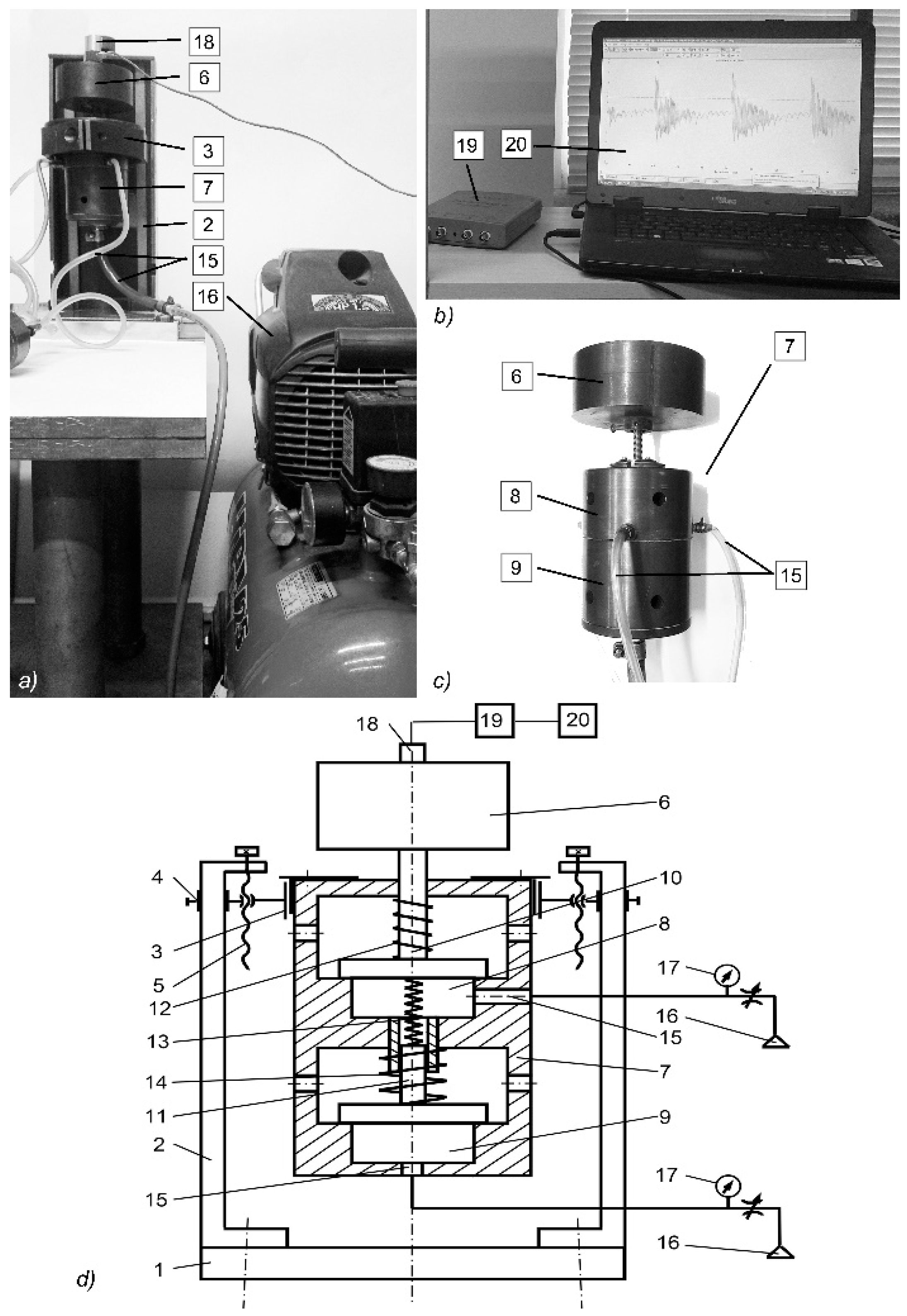
A diagram of a pneumatic dual-chamber vibroactuator with actuating elements connected with the elastic synchronizing link is provided in
Figure 1.
The actuator consists of housing 1, in which two vibroexciters are integrated.
Vibroexciters are supplied with compressed air (gas) P1 and P2. Other parameters influencing the movement of actuating elements 5 are m1, m2′, and m2′′—mass; K1, K2—resistance factor; C1, C2—stiffness factor; x1 and x2—a shift of actuating elements in the chambers. The pressures PK1 and PK2 are generated in chambers 3 and 4. Actuating elements are connected by the elastic link, whose characteristics are described by the stiffness factor of the spring C3 and the resistance factor K3.
The mathematical model was created using formulas of De Saint Venant and Vantzel, adapted to two vibroexciters operating in a single mechanical system.
The entire system is described by the two differential equations of the second order describing the movement of the actuating element of each vibroexciter (masses
m1 and
m2, where
m2 =
m2′ +
m2′′), with account of the synchronizing link:
where
It1 and
It2—initial tightening of vibrating masses
m1 and
m2 that cause the rigidity of the whole system;
Pk1 and
Pk2—the pressure of the compressed air in the chambers;
Pa—the atmospheric pressure (
Pa = 10
5 Pa);
K1,
K2,
K3—resistance coefficient;
C1,
C2,
C3—coefficient of rigidity;
x1 and
x2—vibration amplitude of the working body of the chamber.
The mass of gases in the chambers is described by the law of gas mass balance:
where
Qk1 and
Qk2—the mass of gases in chambers,
W11 and
W21—the amount of air supplied to the chambers,
W12 and
W22—the amount of air exhausted from the chambers. In general, the mass of gas in chambers is calculated as follows:
By applying the De Saint Venant and Vantzel equations to the analyzed system, the gas flow
Wj1 entering the chambers
j (
j = 1, 2) and the flow
Wj2 exhausted from the chambers can be described by Equations (6) and (7):
Therefore, the overall dynamics of the two vibroexciters connected with the synchronizing elastic link can be described by the system of Equations (1)–(4), where expressions Equations (5)–(7) are used.
For the solution, the system of differential equations of the first and the second degree is transferred to the system of six equations of the first degree, which are solved using the approach based on the Runge–Kutta method, with a variable (with the set accuracy of solution) and a fixed number of integration steps. The solution was implemented using a MathCad basis.
Differential equations are described in matrix Equation (8), where members changing in time t are recalculated in separate procedures for each time moment.
Here, expressions of functions
f1 and
f2 are found, respectively, from Equations (1) and (2), and the functions
f3 and
f4 (change of pressure in the chambers of vibroexciters within the unit of time t) are derived from Equations (3)–(7):
4. Results and Discussion
4.1. Results of Numerical Research and Their Analysis
Geometric parameters (rk1, lk1, r1, rk2, lk2, r2), as well as the values of initial tightening Hz, the values of pressure P1 and P2 supplied to the chambers, and the values of masses m1 and m2 of the actuating elements, have been varied during the digital research. To make sure that the synchronizing link influences the vibration of the actuating elements, initially, the theoretical model was researched without an account of the spring connecting the actuating elements, i.e., vibroexciters have been operating independently (without the synchronization link). Then, it has been monitored how the character of the vibration is influenced by the introduction of the synchronizing spring between the vibroexciters.
In the case of the following initial data set, No. 1 from
Table 1, of the first vibroexciter:
rk1 = 25 × 10
−3 m,
rk2 = 30 × 10
−3 m,
ra1 =
ra2 = 30 × 10
−3 m,
r1 =
r2 = 2.0 × 10
−3 m,
lk1 =
lk2 = 40 × 10
−3 m,
P1/
Pa = 1.6,
m1 = 1.0 kg,
P2/
Pa = 2.0,
m2 = 1.5 kg,
It1 =
It2 = 2 × 10
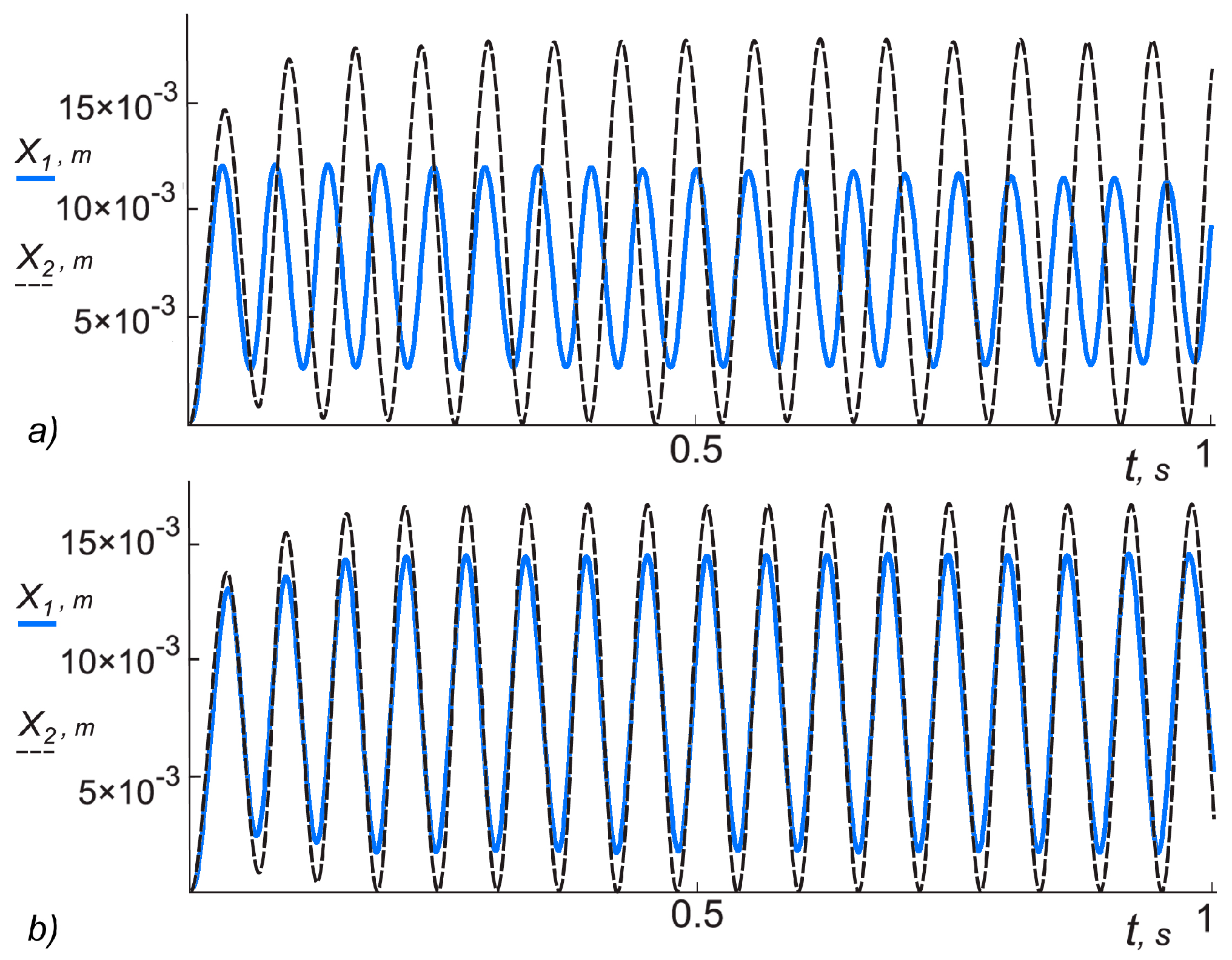
−3 m, autovibrations of a different frequency are generated in the vibroexciters (
Figure 3a) with a different amplitude:
A1 = 4.48 × 10
−3 m,
f1 = 19.29 Hz,
A2 = 8.81 × 10
−3 m,
f2 = 15.59 Hz. After activation of the synchronizing link with the parameters
C3 = 5900 N/m and resistance (damping) factor
K3 = 30 Ns/m, vibrations of the equal phase and frequency are established:
f′
1 =
f′
2 = 16.74 Hz (
Figure 3b).
The digital research results show that the vibrations of individual actuating elements of vibroexciters can be synchronized by connecting them with a spring.
In the case of data set No. 2 from
Table 1, when other initial data of the first vibroexciter are the following: tightening
It1 = 2 × 10
−3 m, tightening of the second vibroexciter
It2 = 1 × 10
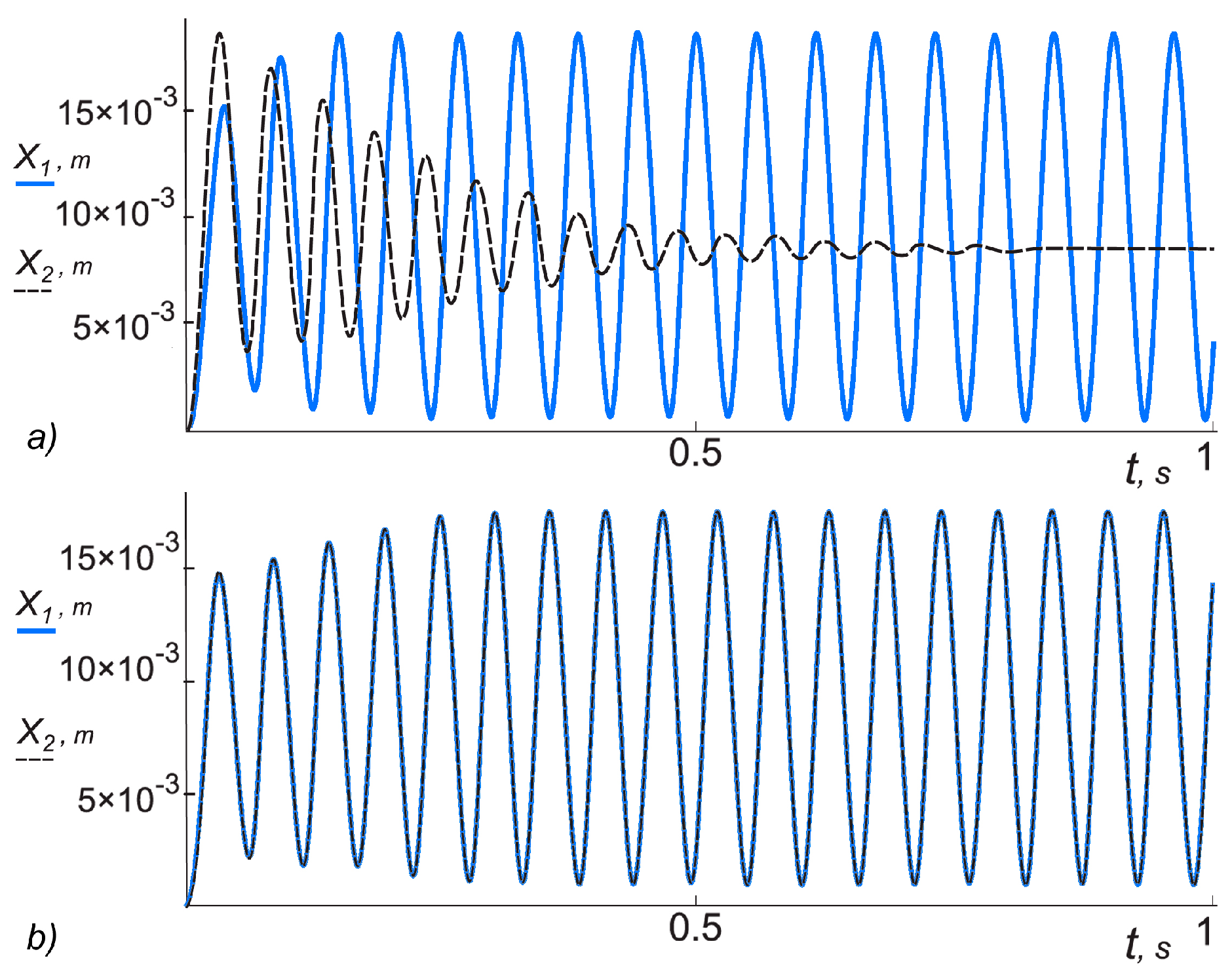
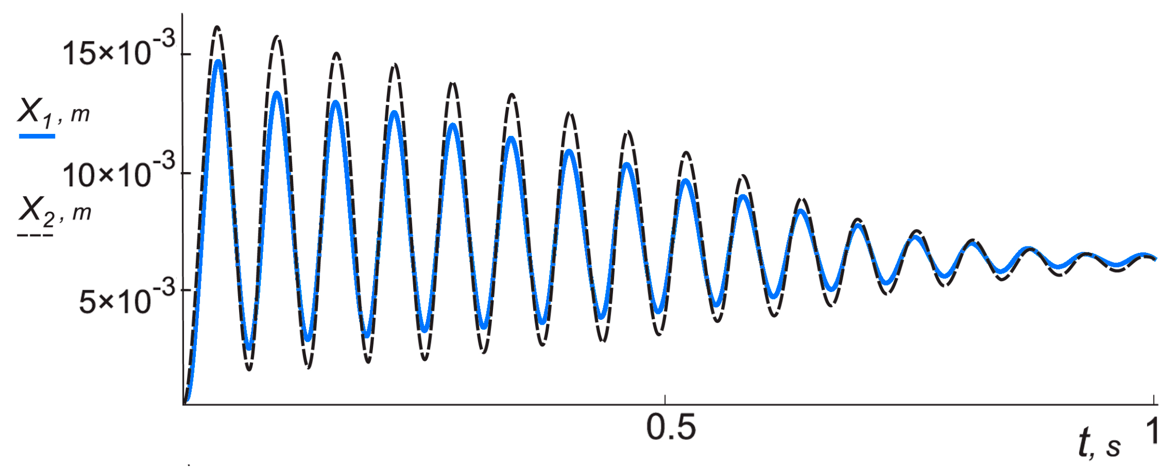
−3 m, vibrations of different characters are generated in the vibroexciters during the independent operation mode: autovibrations with amplitude
A1 = 8.92 × 10
−3 m and
f1 = 17.50 Hz are recorded in the first chamber, and in the second chamber, vibrations with initial frequency
f2 = 20.02 Hz fade out after 0.8 s (
Figure 4a). When the synchronizing link is activated with the parameters:
C3 = 5900 N/m, resistance (damping) factor
K3 = 30 Ns/m, vibrations of equal amplitude and equal frequency are established in both chambers (
Figure 4b).
In the case of data set No. 3 from
Table 1, the same initial tightening,
Iti, and the independent mode, autovibrations with amplitude
A1 = 4.48 × 10
−3 m,
f1 = 19.29 Hz are recorded in the first chamber, and extinguishing vibrations are observed in the second chamber with higher amplitude than in the first chamber and frequency
f2 = 14.9 Hz (
Figure 5).
When the synchronizing link is activated, fading out vibrations with equal frequency and equalizing amplitude are observed in both chambers (
Figure 6). The amplitude of vibrations in the first chamber has increased, and the frequency has reduced. Meanwhile, the vibration frequency in the second chamber has increased.
In the case of data set No. 4 from
Table 1, the frequency of autovibrations obtained in the first chamber in the independent operation mode is 1.78-fold (
Figure 7a); however, when the synchronizing link is activated, autovibrations of equal frequency are established in both chambers, regardless that the amplitudes are different (
Figure 7b).
In the case of data set No. 5 from
Table 1, the difference of the vibrations of actuating elements operating in an independent mode is increased up to twofold (
Figure 8a). After activation of the synchronizing link, autovibrations of equal frequency are established after a time period
t = 0.08 s; however, the actuating element in the first chamber moves following anharmonic law (
Figure 8b).
When we are further increasing the difference of vibration frequencies of actuating elements operating independently, using data set No. 6 from
Table 1, the time of transition to a synchronized operating mode after activation of the synchronizing link increases up to
t = 0.13 s, and vibrations of the actuating element of the first chamber are anharmonic.
Data sets No. 7 and No. 8 from
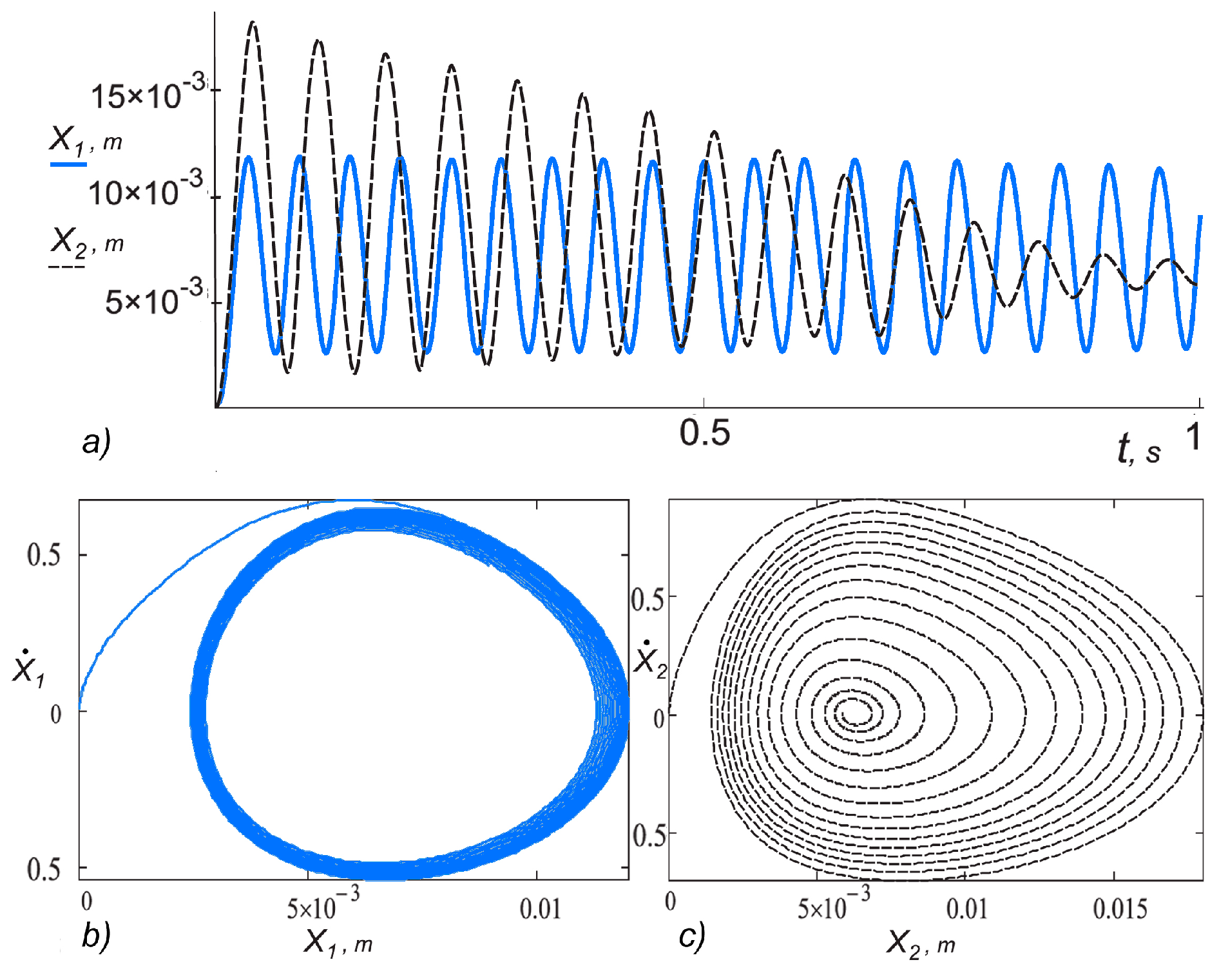
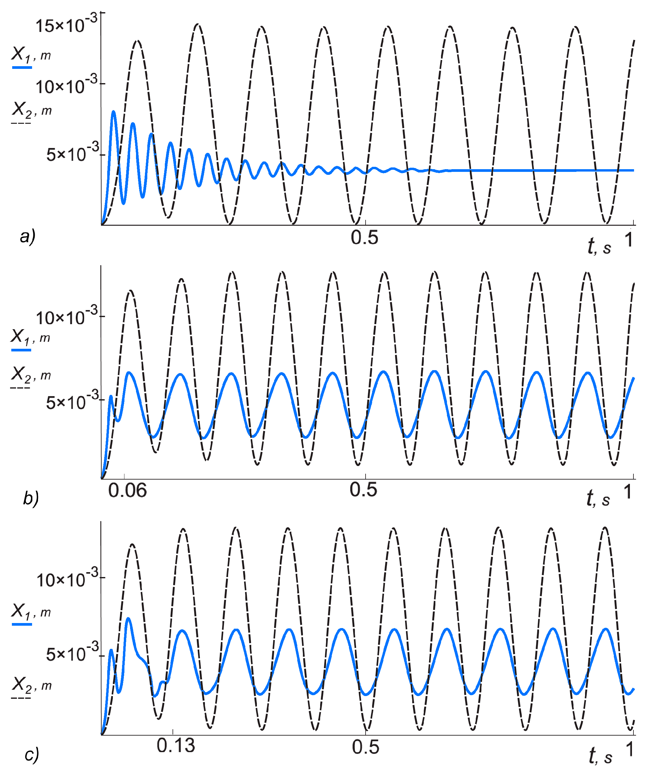
Table 1 are used to study the influence of the synchronizing link on vibrations of both chambers. Vibrations of actuating elements operating in the independent mode were different characters: vibrations in the first chamber have been fading out, and vibrations in the second chamber were harmonic (
Figure 9a). When the synchronizing spring with resistance (damping) factor
K3 = 30 Ns/m is activated, autovibrations with equal frequency are established in both chambers after time period
t = 0.057 s (
Figure 9b).
In the case of the resistance (damping) factor of the synchronizing spring
K3 = 10 Ns/m, autovibrations of the same frequency have been established after a longer time period
t = 0.13 s (
Figure 9c), and amplitudes of the vibration itself have increased, and frequencies have decreased.
After choosing the initial data for the theoretical study (data sets No. 9 and No. 10 from
Table 1), which correspond to the parameters of the mechanical system used during the experiment, presented in Test No. 3 and No. 4 from
Table 2 (
rk1 = 25 × 10
−3 m,
rk2 = 25 × 10
−3 m,
ra1 =
ra2 = 30 × 10
−3 m,
r1 =
r2 = 2.0 × 10
−3 m,
lk1 = 10 × 10
−3 m,
lk2 = 30 × 10
−3 m,
P1/
Pa = 2.2,
m1 = 0.83 kg,
P2/
Pa = 6.0,
m2 = 1.03 kg,
It1 =
It2 = 2 × 10
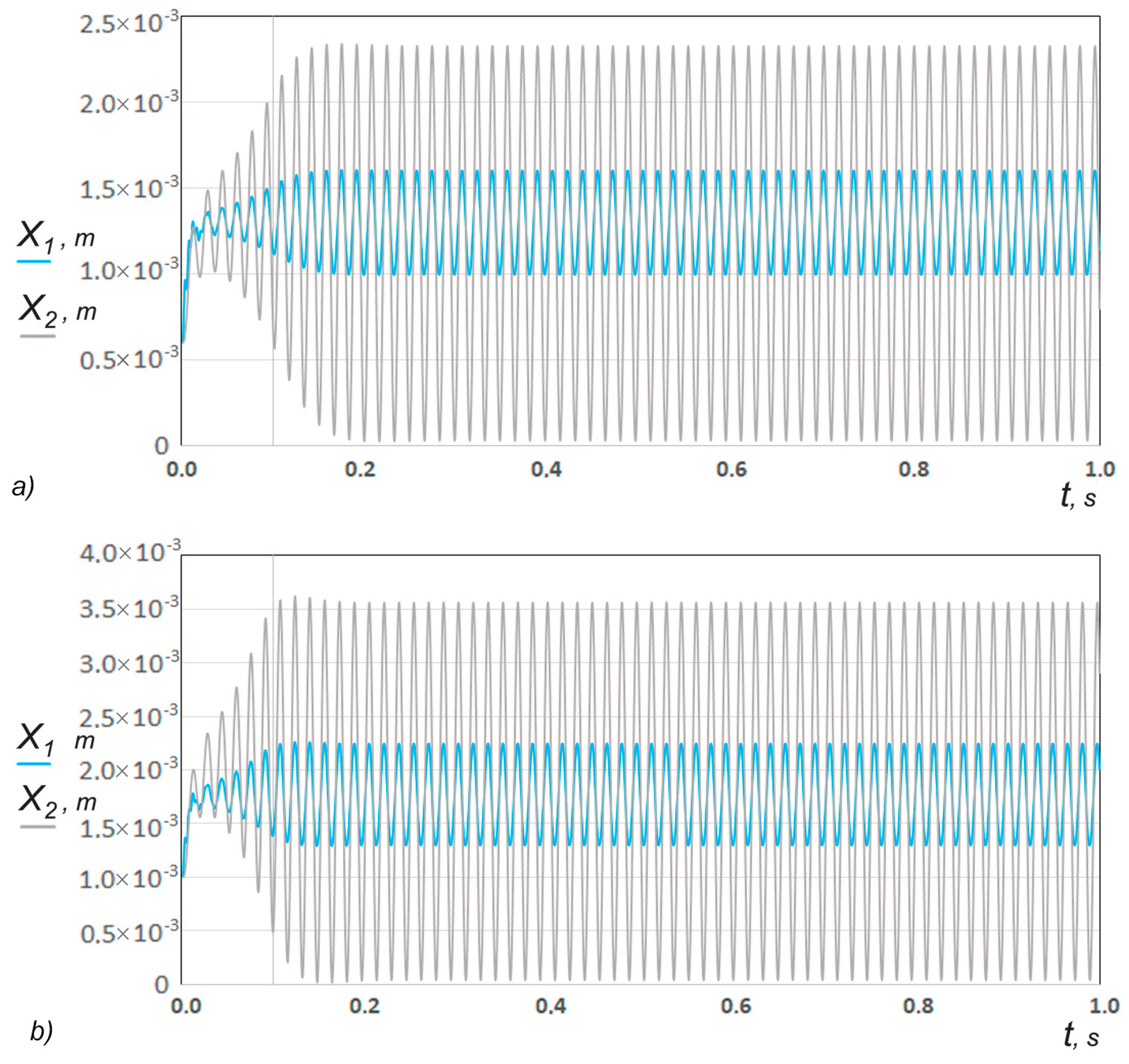
−3 m), autovibration amplitudes
A1 = 4.6 × 10
−4 m,
A2 = 1.80 × 10
−3 m and vibrational frequency
f1 =
f2 = 61.8 Hz (
Figure 10a) were obtained. After reducing the supplied pressure to the second chamber
P1/
Pa = 2.2,
P2/
Pa = 3.0, the vibration amplitudes in both chambers decreased:
A1 = 3.6 × 10
−4 m,
A2 = 1.15 × 10
−3 m, and the oscillation frequency became
f1 =
f2 = 58.2 Hz (
Figure 10b).
4.2. Results of Experimental Research
Initial data of the mechanical system, also the values of amplitude
A and frequency
f of resulting vibrations, are presented in
Table 2.
During experimental Test No. 1 and No. 2 (according to the values and parameters in
Table 2), the pressure was applied to only one chamber. Pressure
P1 that was fed to the first chamber was changed when the pressure
P2 = 0. The tests show that decreasing the value of the supply pressure
P1 reduces the amplitude of vibration from 1.12 × 10
−3 to 7.19 × 10
−4 m (
Figure 11).
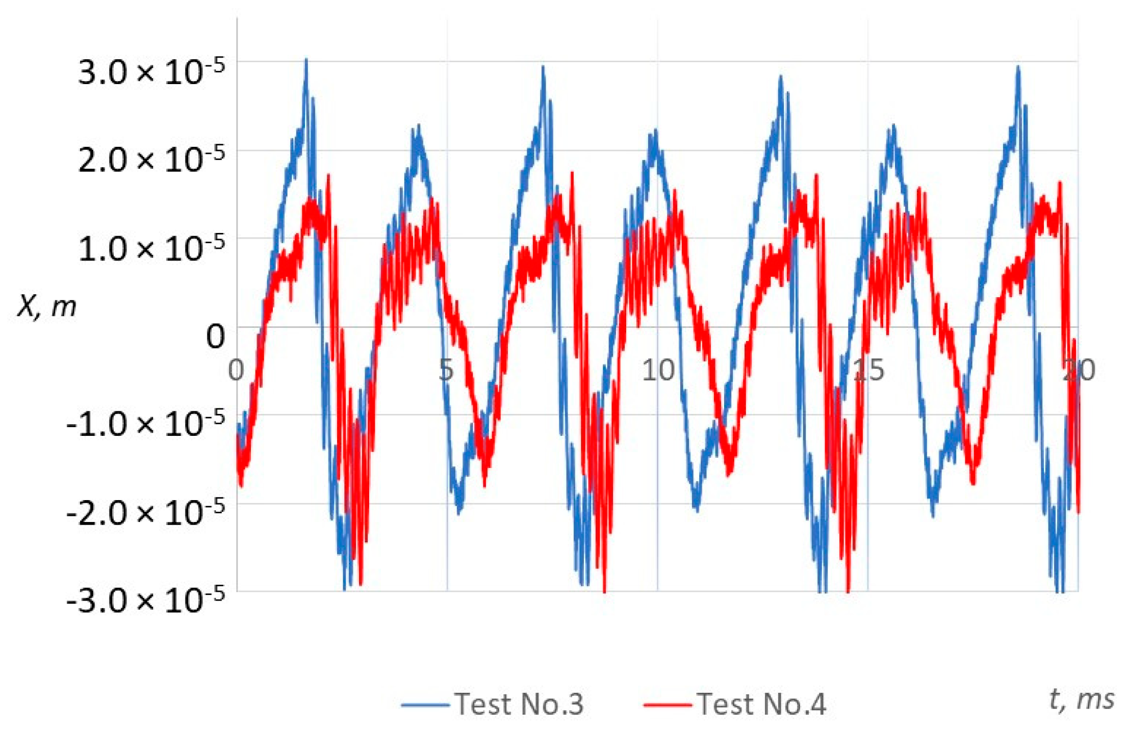
The vibration amplitudes obtained in Test No. 3 and No. 4 are shown in
Figure 12. During these experiments, constant pressure is applied to the first chamber (
P1/
Pa = 2.2) when the pressure
P2 that was fed to the other chamber is changed (
P2/
Pa = 6.0 and
P2/
Pa = 3.0). The results show that a decrease in the supply pressure
P2 reduces the vibration amplitude from 3.38 × 10
−5 to 3.03 × 10
−5 m; the frequency also reduces from 179.1 to 173.9 Hz.
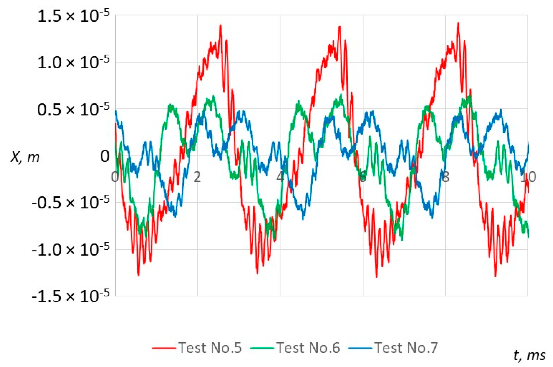
The vibration amplitudes obtained in Tests No. 5–7 are shown in
Figure 13. During these experiments, the pressure was applied only to the second chamber (
P2/
Pa = 5.0,
P2/
Pa = 4.0 and
P2/
Pa = 2.5), and the feeding pressure to the first chamber was
P1 = 0. The results show that decreasing the value of the supplied pressure
P2 decreases the amplitude of vibrations from 1.31 × 10
−5 to 6.92 × 10
−6 m. With no pressure to the first chamber, the vibration frequency increased to 344 Hz compared with previous experiments.
The vibrating mass m2′′ was increased during Tests No. 8–11. The results of Test No. 3 and 8 show that after the oscillating mass was increased, and the values of the supplied pressure remained the same; the amplitude of vibrations decreased about seven times.
Comparing the results of Tests 9–11 with the results of Test No. 5–7, it was noticed that increased mass causes the working body to vibrate at a lower amplitude, but at a higher frequency (e.g., Test No. 6 vs. No. 10).
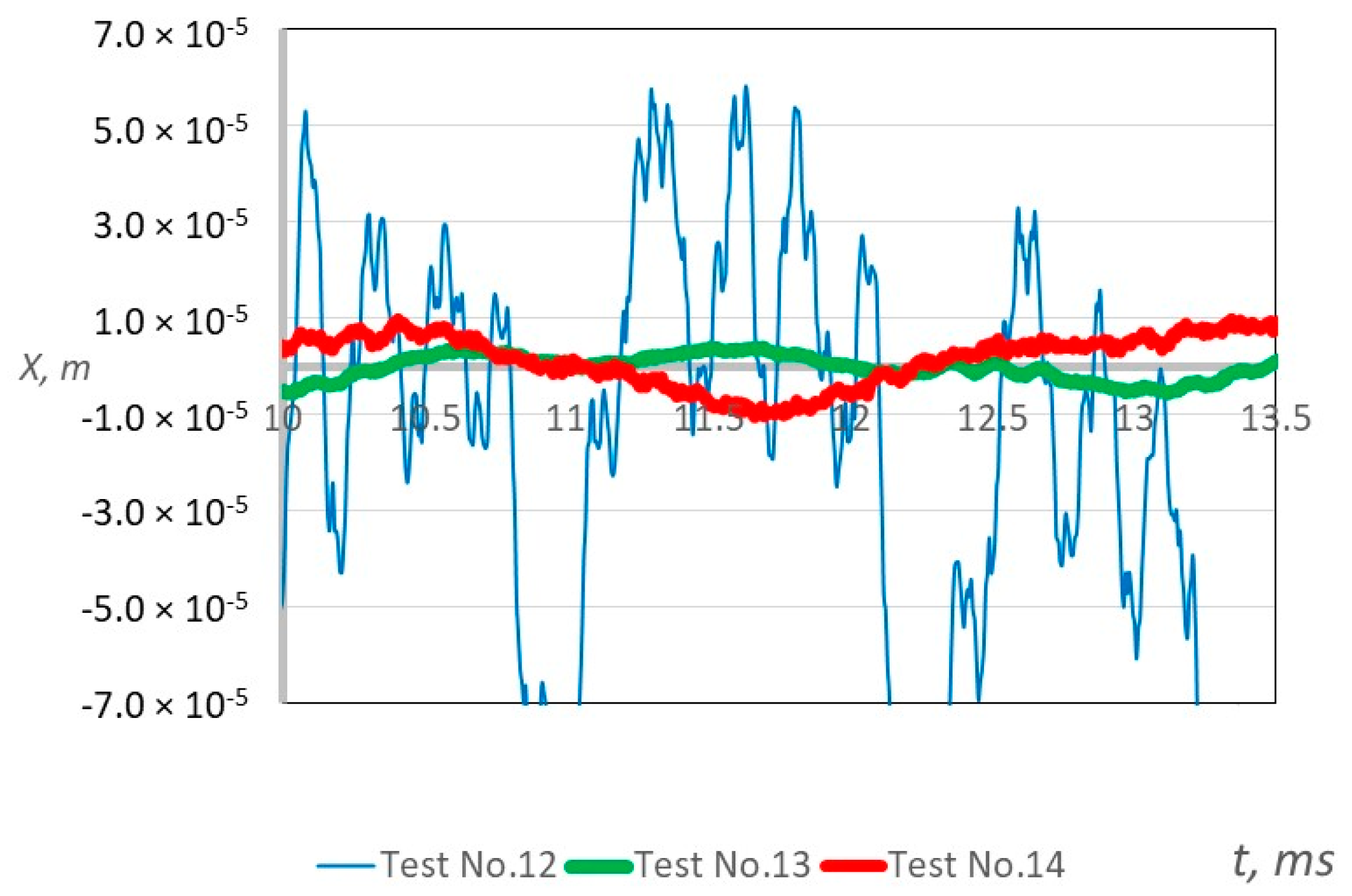
The vibration amplitudes obtained in Test No. 12–14 with a total vibrating mass of 1.57 kg are presented in
Figure 14. The pressure is fed only to the first chamber during Test No. 12:
P1/
Pa = 2.0,
P2/
Pa = 0.0 (blue curve). The amplitude of the resulting non-harmonic vibrations pulsed from 3.82 × 10
−5 to 5.12 × 10
−5 m, and the frequency was about 88.9 Hz.
During Test No. 13, the pressure is applied only to the second chamber P1/Pa = 0.0, P2/Pa = 3.5 (green curve). The amplitude of the obtained vibrations was 0.44 × 10⁻⁵ m, and the frequency of the vibrations stabilized to 168.8 Hz.
During Test No. 14, the pressure was fed to both chambers: P1/Pa = 2.0, P2/Pa = 3.5 (red curve). Pulsating vibrations are obtained, and the amplitude of vibrations was about 1.01 × 10⁻⁵ m. Due to the synchronization effect, the frequency of vibration in the chambers changed to a total frequency of 174.1 Hz.
4.3. Comparison Results of Theoretical and Experimental Research
It should be noted that the vibration characteristics of the working body were measured during the experiment, which correspond to x2 in the theoretical study, where the x2—shift of the actuating element is in the second chamber.
The aim of these studies is to conduct qualitative research, i.e., after performing numerical and experimental studies, it was proved that the pneumatic dual-chamber vibroactuator with actuating elements connected with the elastic link can generate three modes of vibration: harmonic, non-harmonic, and pulsating.
After entering the geometric parameters of the mechanical system into the mathematical model (according to the experimental data from Test 4,
Table 2) it was obtained that the theoretical amplitude
AT = 1.15 × 10
−3 m was about 38 times larger than the amplitude in the experiment and the theoretical frequency
fT = 58.2 Hz (about three times smaller than the frequency in the experiment). The results that are closer to the ones in the experiment are achieved in the first chamber:
AT = 3.60 × 10
−4 m (about three times larger than in the experiment). Such a mismatch of results is due to the lack of precision in the method used to calculate the pressure generated in the vibrator exciter chambers. That is why the adjustment of the mathematical model is required. The fact that the compressors used during the experiment do not ensure constant pressure throughout the test may also contribute to the discrepancy between the theoretical results and the experiment. The pressure
P1 and
P2 applied to the chambers had a slightly pulsating character during the time interval under investigation.
Experimental studies have confirmed that it is possible to synchronize two independently operating vibroexciters using an elastic link. The introduction of a synchronization link forces the working body to move in accordance with one of the laws of independently operating vibrating masses. The character of the resulting vibration (non-harmony and pulsation) may replicate the vibrations of another separately operating vibrator.
The experimental results confirmed the reliance between the characteristics of vibration after the changing geometrical and physical parameters of the system. The experimental research showed the same properties of the results as the theoretical study.
4.4. Control of Different Movement Laws of the Working Body of the Pneumatic Vibroexciter
The peculiarity of this vibroactuator is that depending on the pressure value
P1 supplied to chambers 3, 4 (see
Figure 1), three different laws (modes) of self-vibration of the working body can be obtained (see
Figure 15):
The established harmonic law of motion: when the physical and geometrical parameters of the vibroactuator are as follows: lk1 = lk2 = 40 × 10−3 m, 1.2 ≤ P1/Pa < 2.0, m1 = 1.0 kg, 1.2 ≤ P2/Pa ≤ 2.0, m2 = 1.5 kg;
A well-established non-harmonic law of motion: when the chambers of the vibrators differ lk1 ≠ lk2, (lk1 = 10 × 10−3 m lk2 = 40 × 10−3 m, P1/Pa = 1.5, P2/Pa = 1.6), different frequencies can be achieved by vibrations in individual chambers, and when the difference f2/f1 → 2 and more, inharmonic vibrations settle;
Pulsating motion law: when P1/Pa = 1.0, and P2/Pa > 3.0, with a total oscillating mass m = 1.57 kg, lk1 = 10 × 10−3 m, lk2 = 30 × 10−3 m.
These possible laws of movement of the vibroactuator give it wide possibilities for the intensification of various production technological processes.
5. Conclusions
A mathematical model of the pneumatic vibroactuator was created, which was analyzed by numerical methods.
The significant feature of this multifunctional pneumatic vibroactuator is that it is composed of two excitation chambers with an elastic link, which influences the synchronization of self-excited self-oscillations at the corresponding pressure in the excitation chambers.
Theoretical and experimental studies have shown that the vibroactuator of the studied geometrical and mechanical parameters creates vibrations of the working body, with a frequency ranging from 0 to 400 Hz.
The results of the numerical study show that the time of exit to the synchronous operating mode, after which the single-frequency oscillations settle, in the presence of a synchronizing circuit increases (by changing the system parameters). In this case, the difference in the frequencies of vibrations of the working body working in the independent mode also increases. As long as this frequency difference is less than 1.5 times, oscillation synchronization occurs during the first oscillation cycle. Calculations showed that when the frequency difference becomes equal and greater than two times, non-harmonic self-oscillations settle in one of the chambers.
Numerical and experimental studies have shown that the synchronizing circuit can make the working body oscillate in a single-frequency self-oscillation mode, even in cases where the oscillations in one of the chambers were decaying. However, in another chamber, the working body must oscillate in the mode of self-oscillations, and the amplitude of its self-oscillations is not less than the initial amplitude of decaying vibrations.
Calculations prove that the physical parameters of the synchronizing elastic chain affect the synchronization time and the characteristics of steady oscillations. As the damping constant K of the synchronizing circuit decreases, the working body begins to oscillate with a larger amplitude and lower frequency, and single-frequency self-oscillations settle after a longer time interval.
After evaluating the research results, it can be said that the working body can have the following movement laws:
established harmonic, when the physical and geometrical parameters of the vibrators are as follows: lk1 = lk2 = 40 × 10−3 m, 1.2 ≤ P1/Pa < 2.0, m1 = 1.0 kg, 1.2 ≤ P2/Pa ≤ 2.0, m2 = 1.5 kg;
established non-harmonic, when the chambers of the vibrators differ lk1 ≠ lk2, (lk1 = 10 × 10−3 m lk2 = 40 × 10−3 m, P1/Pa = 1.5, P2/Pa = 1.6), it is possible to achieve vibrations of different frequencies in separate chambers, and when the difference f2/f1 → 2 and more, inharmonic oscillations settle;
pulsating amplitudes, when P1/Pa = 1.0, and P2/Pa > 3.0, with a total vibrating mass m = 1.57 kg, lk1 = 10 × 10−3 m, lk2 = 30 × 10−3 m.
The obtained research results showed the wide functional possibilities of the studied pneumatic self-exciting vibroactuator. All these modes can be used to intensify various production technological processes.

