Abstract
The inkjet printing technology, based on piezoelectric microjet, realizes the high-efficiency processing of special-shaped structures, and has the advantages of high precision, high efficiency, and the ability to manufacture arbitrary complex parts. In this paper, a self-priming piezoelectric micro-jet device is proposed and its structure and microjet process are described. ANSYS two-phase two-way fluid-structure coupling simulation analysis is carried out, and the mechanism of the piezoelectric microjet is described in detail. The effects of voltage amplitude, input signal frequency, nozzle diameter, and oil viscosity on the ejection performance of the device are studied, and a set of effective control methods are summarized. Finally, the correctness of the piezoelectric microjet mechanism and the feasibility of the proposed self-priming piezoelectric micro-jet device are verified by experiments, and its ejection performance is tested. The experimental results are consistent with the ANSYS simulation results, which verifies the correctness of the experiment.
1. Introduction
Piezoelectric microjet is a kind of micro-droplet injection technology based on piezoelectric drive, through which fluid is ejected into tiny droplets, and droplets can be ejected on demand [1,2]. It has outstanding advantages such as high injection precision, fast response speed, high efficiency, and a wide range of injection materials [3,4], and has been widely used in many industrial fields, such as microelectronic manufacturing [5], medical [6], chemistry [7], biology [6,8], space bearing lubrication [9], underwater drive [10], microfluid filtration [11], additive manufacturing [12,13,14], etc.
Modern micro-structure products are developing rapidly in the direction of being more compact, multifunctional, and convenient, and have higher requirements on quality and reliability [15]. Additive manufacturing technology breaks through the limitations of traditional processing technology, realizes the efficient processing of special-shaped structures, has the advantages of high precision, high efficiency, and can manufacture arbitrary complex parts, and develops rapidly in the engineering field [16]. At present, the additive manufacturing technologies used in the engineering field mainly include fused deposition modeling [17], selective laser sintering [18], and inkjet printing [19]. Among these technologies, inkjet printing technology is an important research direction, and its droplets can be ejected with PL-level accuracy [15,20]. Compared with fused deposition modeling and selective laser sintering, the inkjet printing technology based on piezoelectric microjet has the advantages of high printing accuracy, high material utilization rate, low cost, fast dynamic response, simple structure, no electromagnetic interference, green environmental protection, and so on [21]. With the development of droplet inkjet printing, more and more researchers pay attention to piezoelectric microjet.
Existing piezoelectric micro-jet devices can be roughly divided into five types according to the deformation mode of piezoelectric vibrators: squeeze type, bend type, push type, shear type, and needle-collision type [1,22]. Li et al. [23] produced an interchangeable nozzle squeeze type piezoelectric inkjet printing device, whose printing chamber consisted of PET or PTFE tubes, which could eject liquids with a viscosity up to 100 cps, achieving a maximum injection frequency of 5 kHz and a stable injection frequency of 1.5 kHz. Shen et al. [24] designed a bend-type cymbal-shaped micro-jet device consisting of annular piezoelectric ceramics and cymbal-shaped micronozzle plates. Under the condition of 127.89 kHz, ultrafine droplets with a particle size of less than 4.07 μm were obtained, and the atomization rate was 0.5 mL/min. Tzvi et al. [25] designed a push-type micro-jet device capable of producing droplets with an accuracy of several PL. Yang et al. [26] proposed a shear-type micro-jet device, which produced a droplet with a diameter of about 12 μm and a volume of about 905 fL at a driving voltage of 160 Vpp. Zhou et al. [27] produced a needle-collision type piezoelectric print head that expanded the viscosity range of the ejected droplets by using a layered piezoelectric ceramic structure. It could eject droplets with a viscosity of 120 cps. Wang et al. [28] proposed a needle-collision type piezoelectric micro-jet device driven by piezo stack, and the maximum jetting frequency of 65 Hz and the droplet diameter of 1.07 mm were realized using the stainless steel nozzle with a diameter of 0.25 mm.
Although the existing piezoelectric micro-jet devices have a series of advantages such as high injection control precision and fast dynamic response speed, they all need a set of liquid supply systems, which will greatly increase the overall volume of the device, reduce the effective volume utilization rate and increase the energy consumption of the system. In the pursuit of the micro size and compact structure of aerospace or military fields, a piezoelectric micro-jet device without a liquid supply system is urgently needed. This project proposes a self-priming piezoelectric micro-jet device based on capillary action. By using the self-priming effect, the piezoelectric nozzle can continuously supply liquid without energy consumption in the absence of a liquid supply system. By using the external piezoelectric nozzle, the micro-droplet can be efficiently ejected on demand.
2. Structure and Mechanism
The self-priming piezoelectric micro-jet device proposed in this work is shown in Figure 1, in which Figure 1a is the overall view of the device and Figure 1b is the section view of the device. The piezoelectric micro-jet device is composed of a cover, a cavity, an axis, a piezoelectric vibrator, a capillary self-priming rod, four bolts, and nuts, in which viscous fluid is stored in the cavity and transported through the capillary rod. The axis is used to fix the capillary rod and ensure that a liquid film is always formed between the capillary rod and the piezoelectric vibrator. Among them, the cover, cavity, and axis are 3D printed with PLA material. The outer diameter of the cover is 40 mm, the inner diameter of the cover is 27.6 mm and 26 mm respectively, and the height is 11 mm. The outer diameter of the cavity is 40 mm, the inner diameter is 30 mm, the height is 16.5 mm, the outer diameter of the axis is 40 mm, the inner diameter is 8 mm, and the height is 13 mm. Bolts and nuts are used for connecting and fixing devices. As an important component of the micro-jet device, the piezoelectric vibrator is composed of a customized PZT ceramic with a diameter of 19 mm and a thickness of 0.2 mm and a cooper sheet (red cooper) with a diameter of 27 mm and a thickness of 0.2 mm, which is fixed on the upper cover with epoxy resin (LEAFTOP 9005).
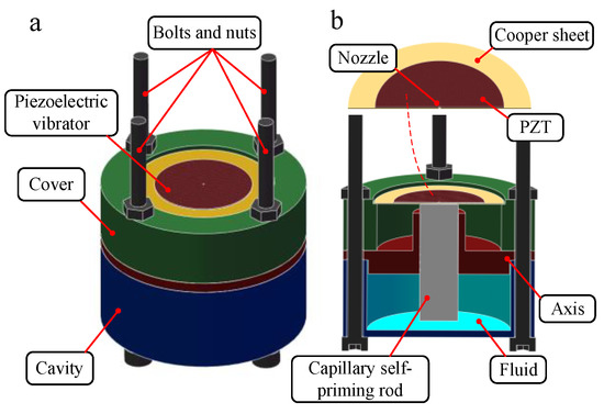
Figure 1.
The overall structure and section view of piezoelectric micro-jet device: (a) The overall structure of piezoelectric micro-jet device; (b) The section view of piezoelectric micro-jet device.
A nozzle is drilled in the center of the piezoelectric vibrator, and its operation process of ejecting viscous fluid is shown in Figure 2. The viscous fluid used is silicone oil with a density of 0.963 g/mL and a surface tension of 21.0 dyn/cm at room temperature. When the piezoelectric vibrator does not work, as shown in Figure 2a, a liquid film is formed between the vibrator and the capillary self-priming rod. When periodic square wave signals are applied to the vibrator, the vibrator vibrates and deforms, and the nozzle starts to periodically eject liquid. As shown in Figure 2b, when the vibrator produces concave deformation downward, the copper sheet squeezes the liquid film between the vibrator and the capillary rod downward, and the viscous fluid converges towards the nozzle and generates droplets. As shown in Figure 2c, when the vibrator produces convex deformation upward, the liquid droplet further obtains kinetic energy driven by the vibrator, separates from the liquid film to form an independent droplet, and is ejected with initial kinetic energy. It can be seen from the above analysis that the viscous fluid is periodically and uniformly ejected with the periodic deformation of the piezoelectric vibrator.
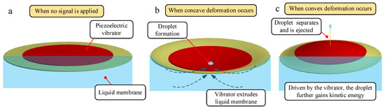
Figure 2.
The ejection process of droplets: (a) When no signal is applied; (b) When concave deformation occurs; (c) When convex deformation occurs.
In order to further reveal the principle of piezoelectric micro-jet and study the influence of signal, fluid viscosity, and nozzle size on the micro-jet operation, we use ANSYS software to carry out a two-phase two-way fluid-structure coupling analysis on the designed piezoelectric micro-jet device. Unlike the device structure diagram, the simulation model and boundary condition setting are shown in Figure 3. As can be seen from the axonometric view of the model in Figure 3a, in order to speed up the simulation calculation and ensure the simulation accuracy, the model omitted the cover, axis, cavity, bolts, and nuts which have little influence on the simulation results, and replaced them with corresponding boundary conditions. As can be seen from the front view of the model in Figure 3b, in order to simulate the shooting of viscous fluid from the nozzle into the air, a fluid domain simulating the external air environment is added on the left side of the vibrator nozzle. The piezoelectric vibrator is set as the structural domain, and the rest of the models are set as the fluid domain. Among them, the fluid in the fluid domain on the left side of the nozzle is air, and the fluid in the fluid domain containing the capillary self-priming rod on the right side of the nozzle is a viscous fluid. PZT-5H is selected as the material of PZT ceramics with Young’s modulus of 56 GPa, Poisson’s ratio of 0.36, and density of 7600 kg/m3. The copper sheet is made of copper with Young’s modulus of 108 GPa and Poisson’s ratio of 0.32. The simulation model ignores the epoxy layer because it is too thin and has little effect on the simulation results. The transient structure analysis module and fluent module are combined to simulate the two-phase two-way fluid-structure coupling analysis.
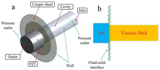
Figure 3.
The simulation mode and boundary condition setting: (a) The axonometric view of the simulation model; (b) The frontal view of the simulation model.
In the transient analysis module, the fixed boundary conditions are applied to the circumference of the copper plate in order to simulate the situation that the piezoelectric vibrator is fixed on the cover by glue. The surface where the piezoelectric vibrator contacts the fluid domain is set as the fluid-solid interface and a square wave pulse signal is applied to the piezoelectric vibrator. In the fluent module, the fluid domain is meshed by the sweep method, and the mesh size is set to 0.00005 m. In Models, set the multiphase model to the Volume of fluid model and the viscous model to the Laminar model. Two kinds of fluid air and silicone oil are set in the Materials, and then the two phases of air and silicone oil are opened in the Phases, and the surface tension is set to 0.0072. In Boundary Conditions, the inlet of the fluid domain is set as the pressure inlet, and the pressure value of the inlet is calculated by the capillary force equation based on the actual model. The outlet of the fluid domain is set as the pressure outlet, and the outlet pressure is constant at 0 MPa. In Dynamic Mesh, the dynamic mesh method (remesh and smooth) is used to simulate the dynamic change of the Fluid domain caused by the piezoelectric vibrator deformation through the coupling surface, and the fluid-solid interface is set as System coupling for the two-way coupling analysis. Solution Methods Select the PISO. In order to achieve convergence, the step size should be small enough, and the relaxation factor can be appropriately reduced according to the actual situation of the simulation. In this work, the step size is set to 0.0000065 s.
In order to obtain the best ejection effect, it is necessary to find an optimal ejection frequency. According to the previous study, when the vibrator is in the first-order resonant mode, the amplitude of the vibrator is the largest and the ejection effect is the best. Therefore, the acoustic structure coupling analysis is carried out on the piezoelectric vibrator, and the first six modal frequencies are shown in Figure 4. Through ANSYS simulation analysis, the first-order modal frequency of the vibrator is 728 Hz, so 728 Hz is set as the optimal ejection frequency.
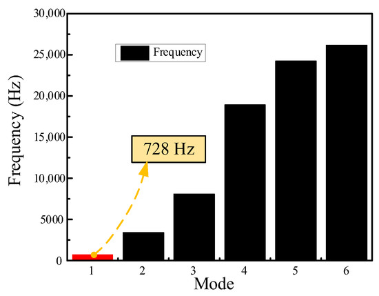
Figure 4.
The results of the acoustic structure coupling analysis.
For the follow-up study on the influence of a single parameter on the ejection state, the basic parameters of the model are set as follows: voltage amplitude is 100 V, signal frequency is 728 Hz, nozzle diameter is 0.4 mm, and fluid viscosity is 200 Pa.s. The single-ejection two-phase flow diagram and streamlined diagram of the piezoelectric micro-jet device under standard parameters are shown in Figure 5 and Figure 6. Figure 5 and Figure 6 correspond one by one in terms of time, and the mechanism of the piezoelectric microjet will be elaborated by combining Figure 5 and Figure 6. At 0, the device has no signal input and no liquid is squeezed into the nozzle. At t1, the high level of the pulse signal is just applied to the piezoelectric vibrator, and the vibrator begins to produce concave deformation and extrude the liquid film between the capillary rod and the vibrator. From t1 to t3, under the influence of a high-level voltage signal, the vibrator continues to squeeze the capillary rod, and the micro-droplets are extruded from the capillary rod and ejected outwards, which interact with the static air outside to generate a vortex ring. At t4, the pulse signal changes to a low level after passing the falling edge. At this time, the vibrator begins to return to its original deformation and the extrusion strength of the capillary rod decreases. Part of the viscous liquid begins to be sucked back by the capillary rod, but the ejected microdroplets continue to move outward and the vortex ring also continues to roll outward and expand. At t5, it can be seen that some droplets are sucked back under a continuous low signal. At t6, the droplets are completely separated from the fluid in the capillary rod and ejected outwards to form satellite droplets. The simulation results show the feasibility of a piezoelectric microjet and describe the droplet generation process in detail.
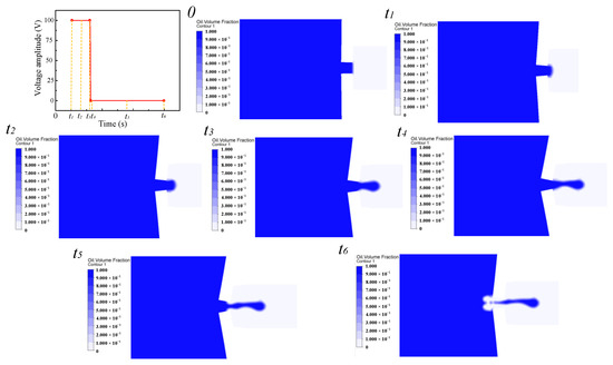
Figure 5.
The single droplet ejection two-phase flow diagram.
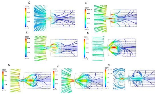
Figure 6.
The single droplet ejection streamline diagrams.
The single ejection velocity diagram of the piezoelectric micro-jet device under standard parameters is shown in Figure 7. From 0 to t6, it can be seen that the droplets converge towards the nozzle and gradually eject outward. In the beginning, the droplet obtains the initial kinetic energy under the action of the vibrator, and the kinetic energy gradually increases. Then, the kinetic energy is gradually lost due to the need to overcome the viscous resistance of the fluid and the re-absorption of the capillary rod, and the velocity of the droplet gradually decreases.
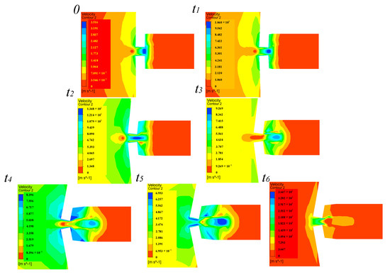
Figure 7.
The single ejection pressure diagram.
The single ejection pressure diagram of the piezoelectric micro-jet device under standard parameters is shown in Figure 8, in which Figure 8a,b correspond to the concave deformation of the piezoelectric vibrator, and Figure 8c,d correspond to the convex deformation of the piezoelectric vibrator. As can be seen from Figure 8a,b, when the piezoelectric vibrator generates the concave deformation, the vibrator squeezes the capillary rod, and the fluid of the capillary rod is squeezed into the nozzle, which gives kinetic energy to the micro-droplet. As can be seen from Figure 8c,d, when the piezoelectric vibrator generates the convex deformation, the interaction force between the vibrator and the capillary rod is weakened, and the capillary rod absorbs the fluid back, which helps the liquid droplet to separate from the viscous fluid. The simulation results are consistent with the conclusions of the droplet ejection analysis above.
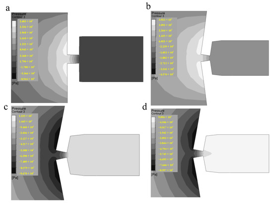
Figure 8.
The single ejection velocity diagram.
3. Performance Controlling
In this work, a self-priming piezoelectric micro-jet device is proposed. In order to test the self-priming performance of the capillary rod used in this work, the liquid supply height of the capillary rod is calculated, and the radius of the capillary rod r = 2 × 10⁻³ cm.
The lifting force F of the capillary liquid column is:
where the σ is the surface tension and θ is the contact angle. The surface tension of the viscous fluid used in this work is 21 dyn/cm and the contact angle is 65°.
The weight G of the liquid column in the tube is:
where the ρ is the density of the viscous fluid used, ρ = 0.96 g/cm3, g is the acceleration of gravity, g = 980 cm/s2, and h is the height of the liquid column in the capillary rod.
The two formulas are equal, the liquid column height h is:
The final calculated liquid column height h is 9.433 cm, which meets the requirements of use (In practical work, the vertical transport distance of fluid does not exceed 10 cm).
In the above part, we describe in detail the basic principle of self-priming piezoelectric microjet and the formation process of single droplet ejection under standard parameters. In order to propose the ejection performance control method of this device, this part will study the influence of various parameters: voltage amplitude, signal frequency, fluid viscosity, and nozzle diameter on the ejection performance. The ejection performance considered in this work mainly includes droplet volume, droplet outlet velocity, and ejection state. The volume of the droplet can be obtained by integrating the flow rate of the nozzle against the time. The outlet velocity and ejection state of the droplet refers to the droplet outlet velocity and ejection state at the moment when the droplet separates from the viscous fluid and is ejected.
The voltage amplitude can affect the ejection performance of the piezoelectric micro-jet device by changing the vibration amplitude of the piezoelectric vibrator. Firstly, the influence of voltage amplitude variation on device ejection performance is studied. Figure 9, Figure 10 and Figure 11 reflects the influence of voltage amplitude variation on device ejection performance. Figure 9 shows the change in the droplet ejection state caused by the change in voltage amplitude. According to the ejection time, the larger the voltage amplitude is, the earlier the droplet is ejected. Increasing the voltage amplitude of the input signal can reduce the difficulty of droplet ejection. Figure 10 and Figure 11 show the change in droplet outlet velocity and droplet volume caused by voltage amplitude change. It can be seen that with the increase of voltage amplitude, the droplet outlet velocity and the volume of the droplet ejected gradually increase, and the ejection efficiency increases while the control accuracy of the droplet decreases. Therefore, if you want to reduce the difficulty of ejection or improve the outlet velocity and ejection efficiency of droplets, you can appropriately increase the voltage amplitude, and if you want to improve the control accuracy of droplets, you can appropriately reduce the voltage amplitude.
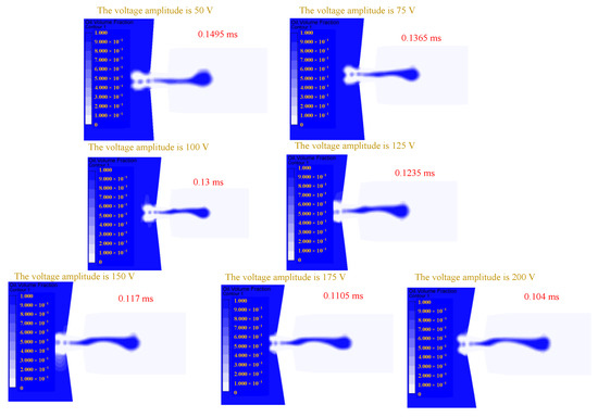
Figure 9.
The change in droplet ejection state caused by the change in voltage amplitude.
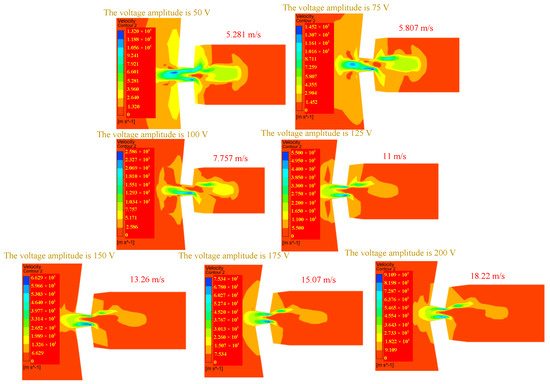
Figure 10.
The change in droplet outlet velocity caused by the change in voltage amplitude.
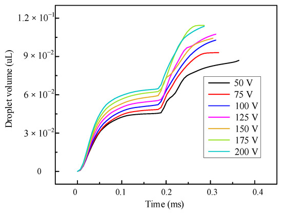
Figure 11.
The change in the volume of droplets ejected caused by the change in voltage amplitude.
The influence of the change of signal frequency on the ejection performance is shown in Figure 12, Figure 13 and Figure 14, which reflects the influence of the change of signal frequency on the ejection performance of droplets. According to the comprehensive analysis of Figure 12, Figure 13 and Figure 14, the influence of frequency change on the ejection performance of droplets is very small, which is a weak influence factor. In the actual experiment, the frequency is not adjusted to adjust the ejection performance of the droplet.
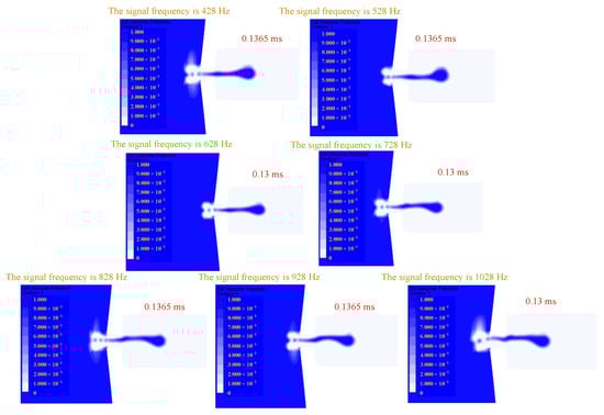
Figure 12.
The change in droplet ejection state caused by the change in signal frequency.
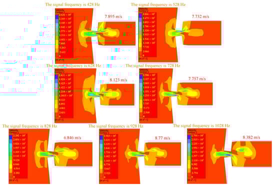
Figure 13.
The change in droplet outlet velocity caused by the change in signal frequency.
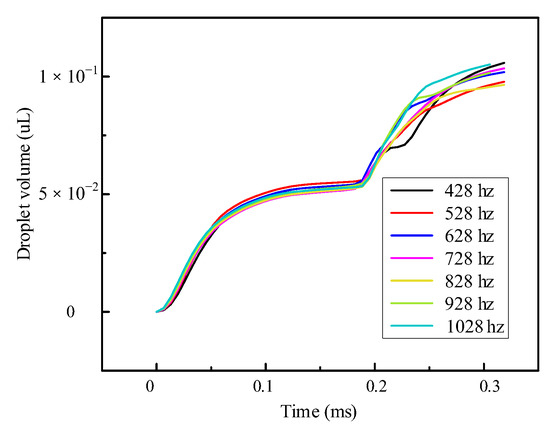
Figure 14.
The change in the volume of droplets ejected caused by the change in signal frequency.
Changing the fluid viscosity will change the viscous resistance of the liquid, and the change of the liquid viscous resistance will lead to a change in kinetic energy loss during the movement of the droplets. The influence of the change of fluid viscosity on the ejection performance is shown in Figure 15, Figure 16 and Figure 17. Figure 15 reflects the influence of fluid viscosity change on the ejection state. It can be seen that with the increase of fluid viscosity, the difficulty of droplet ejection gradually increases, and the ejection time becomes later. Figure 16 shows the influence of fluid viscosity change on droplet outlet velocity. With the increase of fluid viscosity, the larger the kinetic energy loss of the droplet, the lower the outlet velocity. Figure 17 reflects the influence of fluid viscosity change on the volume of ejected droplets. The analysis shows that the larger the viscosity of the viscous fluid is, the volume of ejected droplets tends to decrease gradually, which will improve the control accuracy of droplets and reduce the ejection efficiency. Therefore, in order to reduce the difficulty of ejection or improve the outlet velocity and ejection efficiency of droplets, the fluid viscosity can be appropriately reduced, and if you want to improve the control accuracy of droplets, the fluid viscosity can be appropriately increased. It is worth mentioning that the influence of changing the voltage signal amplitude on the difficulty of droplet ejection and the outlet velocity of droplets is significantly greater than that of changing the fluid viscosity.
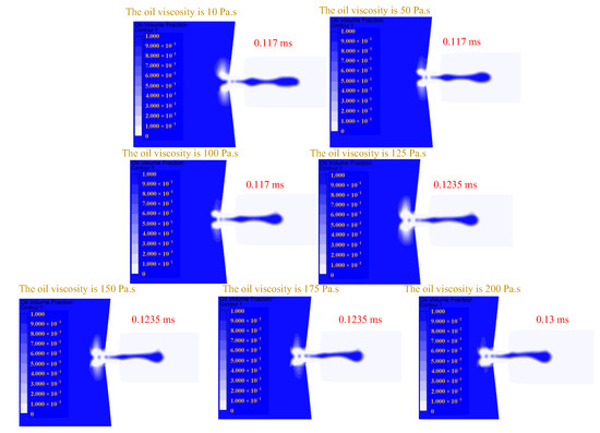
Figure 15.
The change in droplet ejection state caused by the change in oil viscosity.
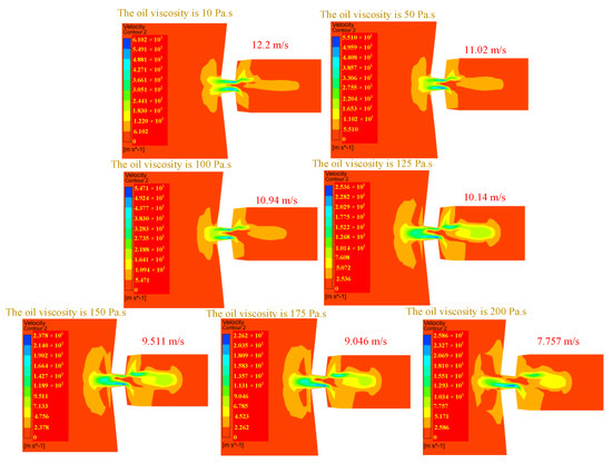
Figure 16.
The change in droplet outlet velocity caused by the change in oil viscosity.
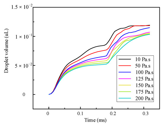
Figure 17.
The change in the volume of droplets ejected caused by the change in oil viscosity.
The influence of the change in nozzle diameter on the ejection performance is shown in Figure 18, Figure 19 and Figure 20. The influence of the change of nozzle diameter on the ejection state of droplets is shown in Figure 18. With the increase of nozzle diameter, the more difficult the ejection of droplets, the later the ejection time of droplets. Figure 19 shows the influence of the nozzle diameter change on the droplet outlet velocity. It can be seen that with the decrease of the nozzle diameter, the droplet outlet velocity increases first and then decreases. This may be because, with the decrease of the nozzle diameter, the difficulty of the droplet ejection decreases, leading to the droplet outlet velocity increasing first. However, when the nozzle diameter decreases to a certain extent, the degree of obstruction to droplets caused by viscous resistance is greater than the degree of help to droplets caused by decreasing nozzle diameter. From this moment on, the outlet velocity of droplets begins to decrease gradually. Figure 20 shows the influence of the nozzle diameter change on the volume of droplets. It can be seen that with the increase of the nozzle diameter, the volume of droplets ejected by the piezoelectric microjet device gradually increases, and the influence of the nozzle diameter on the volume of droplets is significantly greater than that of the voltage amplitude and fluid viscosity. If the volume of the droplets ejected is to be increased to improve the ejection efficiency, the nozzle diameter can be increased appropriately.
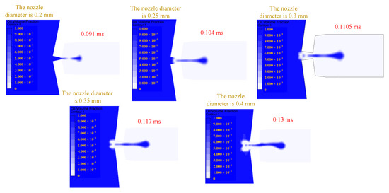
Figure 18.
The change in droplet ejection state caused by the change in nozzle diameter.
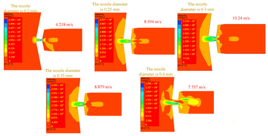
Figure 19.
The change in droplet outlet velocity caused by the change in nozzle diameter.
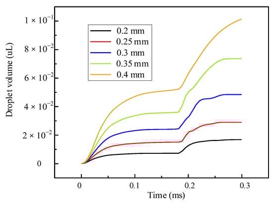
Figure 20.
The change in the volume of droplets ejected caused by the change in nozzle diameter.
Based on the above simulation analysis, it can be seen that frequency regulation has little effect on the ejection performance of piezoelectric micro-jet devices. In order to reduce the difficulty of the ejection, improve the ejection efficiency, and increase the droplet outlet velocity and volume, the following aspects can be considered: increasing the voltage amplitude of the input signal, reducing the nozzle diameter, and adopting low viscosity viscous fluid. If the main consideration is to improve the accuracy of droplet control, we can try to reduce the voltage amplitude of the input signal, increase the nozzle diameter and adopt high-viscosity viscous fluid. The voltage amplitude is the dominant factor in controlling the ejection difficulty and outlet velocity, while the nozzle diameter is the dominant factor in controlling the volume and control accuracy of the ejected droplets. When adjusting the ejection performance of the droplets, adjusting the fluid viscosity can be used as a fine-tuning method. In the above simulation analysis, the accuracy of the micro-jet device can reach up to 16.81 nL with a nozzle diameter of 0.2 mm. Under the voltage amplitude of 200 V and the nozzle diameter of 0.4 mm, the maximum ejection volume of 113.67 nL can be reached, that is, the device proposed in this work has both high efficiency and high precision.
4. Experiment Test
In the above part, the basic mechanism of micro-droplet ejection is explained through ANSYS two-phase two-way fluid-structure coupling simulation analysis, and the influence of each parameter on the device’s ejection performance is analyzed. In this part, an experimental system will be set up to shoot micro-droplet ejection videos with industrial cameras to further verify the feasibility of the proposed device.
In order to verify the feasibility of the proposed device, the experimental system, as shown in Figure 21, is built. The experimental system mainly consists of a prototype, a personal computer (PC), a signal generator (DG4162, RIGOL, Beijing, China), a power amplifier (ATA-4051, Aigtek Inc., Xi’an, China), and an industrial camera (A5031MU815, iRAYPLE, China, Zhejiang). The experimental steps are as follows: Firstly, a certain viscosity viscous fluid (silicone oil) is injected into the prototype, then a given square wave signal is input to the prototype through the signal generator and power amplifier, and then the industrial camera is started to record the ejection process. Finally, the video taken by the industrial camera is exported and analyzed by PC.
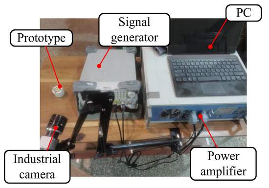
Figure 21.
The experimental system.
The parameters of the experiment are set as follows: voltage amplitude 100 V, square wave signal frequency 728 Hz, nozzle diameter 0.4 mm, fluid viscosity 200 Pa.s. The results of the ejection experiment are shown in Figure 22. Figure 22a is the state of the piezoelectric micro-jet device when it is not working, and Figure 22b–d are the ejection diagram of the piezoelectric micro-jet device after the given square wave signal is applied. Figure 22b–d, respectively, correspond to droplets just extruding from the nozzle, droplets separating from viscous fluid and being ejected and forming satellite droplets, which are in accordance with the simulation in the above part, further verifying the correctness of the ejection mechanism revealed. It can be seen from the observation that after the device works, the size of the droplets ejected is uniform and the ejection state is stable, which can realize the long-term continuous and stable ejection, which confirms the correctness of the piezoelectric microjet principle and the feasibility of the proposed piezoelectric micro-jet device. The experimental video is attached.
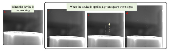
Figure 22.
The results of the ejection experiment: (a) The state of the piezoelectric micro-jet device when it is not working; (b) The droplet extruding from the nozzle; (c) The droplet separating from the viscous fluid and being ejected; (d) The formation of satellite droplets.
In this work, the verification experiment is carried out according to the simulation content in the previous part. The main research is to investigate the outlet velocity and droplet volume of the piezoelectric micro-jet device under different voltage amplitude, signal frequency, fluid viscosity, and nozzle diameter. The standard experimental conditions are set as follows: voltage amplitude 100 V, signal frequency 728 Hz, nozzle diameter 0.4 mm, fluid viscosity 200 Pa.s. The experimental results of voltage amplitude, signal frequency, fluid viscosity, and nozzle diameter on droplet outlet velocity are shown in Figure 23. The experiment is measured several times, and 10,000 pulse signals are applied each time. Then, the average value of multiple experimental results is taken as the final result, and the error bars are the standard error of the mean (SEM). The experimental results are consistent with the simulation results in the above part, and the errors are all within the acceptable range. The maximum error of Figure 23a–d is 11.838%, 14.68%, 12.189%, and 13.55%, respectively.
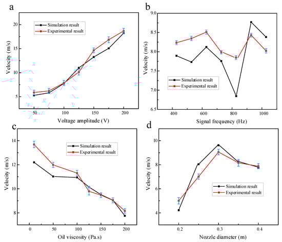
Figure 23.
The experimental results of voltage amplitude, signal frequency, oil viscosity, and nozzle diameter on droplet outlet velocity (The error bars are the standard error of the mean): (a) The experimental results of voltage amplitude on droplet outlet velocity; (b) The experimental results of signal frequency on droplet outlet velocity; (c) The experimental results of oil viscosity on droplet outlet velocity; (d) The experimental results of nozzle diameter on droplet outlet velocity.
The experimental results of voltage amplitude, signal frequency, fluid viscosity, and nozzle diameter on droplet volume are shown in Figure 24. Ten thousand pulse signals are applied to the micro-jet device, the total ejected droplets are weighed, and then the volume of individual droplets is inversely calculated by density. The experimental results are consistent with the simulation results in the above part, and the errors are all within the acceptable range. The maximum error of Figure 24a–d is 6.16%, 9.749%, 10.06%, and 12.093%, respectively.
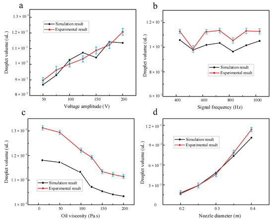
Figure 24.
The experimental results of voltage amplitude, signal frequency, oil viscosity, and nozzle diameter on droplet volume (the error bars are the standard error of the mean): (a) The experimental results of voltage amplitude on droplet volume; (b) The experimental results of signal frequency on droplet volume; (c) The experimental results of oil viscosity on droplet volume; (d) The experimental results of nozzle diameter on droplet volume.
5. Conclusions
This project proposes a self-priming piezoelectric micro-jet device based on capillary action. By using the self-priming effect, the liquid supply system required by most of the piezoelectric micro-jet devices is eliminated, realizing the liquid supply without energy consumption, greatly reducing the overall volume of the device, improving the effective volume utilization rate and reducing the energy consumption of the system. An external piezoelectric nozzle can be used for the efficient ejection of microdroplets on demand.
Based on the brief description of the structure of the device and the process of the microjet, the ANSYS two-phase two-way fluid-structure coupling simulation analysis is carried out, and the mechanism of the piezoelectric microjet is elaborated in detail. On the basis of determining the optimal ejection frequency, the influences of voltage amplitude, input signal frequency, nozzle diameter, and fluid viscosity on the ejection performance of the proposed device are studied, and a set of control methods is proposed based on these. The frequency adjustment has little influence on the ejection performance. Increasing the voltage amplitude, decreasing the nozzle diameter, and decreasing the fluid viscosity will reduce the difficulty of the ejection, increase the volume of droplets and improve the ejection efficiency of the device, but the control accuracy of droplets will decrease. In addition, the voltage amplitude is the dominant factor to control the difficulty of ejection and the outlet velocity. The outlet velocity of the droplet increases rapidly with the increase of the voltage amplitude. The nozzle diameter is the dominant factor to control the volume and control accuracy of the droplet, and the adjustment of fluid viscosity can be used as a fine adjustment method. Finally, this work proved the correctness of the piezoelectric microjet mechanism and the feasibility of the proposed self-priming piezoelectric micro-jet device through experiments and carried out the ejection performance test experiment, which mainly investigated the effects of voltage amplitude, signal frequency, fluid viscosity and nozzle diameter on the droplet outlet velocity and droplet volume. The experimental results show that the piezoelectric micro-jet device has a maximum droplet outlet velocity of 18.678 m/s and a maximum droplet volume of 120.67 nL at a voltage amplitude of 200 V, while the device can achieve a maximum droplet accuracy of 18.128 nL at a nozzle diameter of 0.2 mm. From the above mentioned, it can be seen that the device combines high precision and high efficiency excellently. The experimental results coincide with the ANSYS simulation results, which confirms the correctness of the simulation experiment.
Author Contributions
Conceptualization, T.S. and X.W.; methodology, T.S. and X.W.; software, H.Z.; validation, X.L. and B.Y.; formal analysis, T.S. and B.Y.; investigation, T.S.; resources, X.W.; data curation, B.Y.; writing—original draft preparation, T.S.; writing—review and editing, T.S. and X.W.; visualization, X.W.; supervision, X.W.; project administration, X.W. All authors have read and agreed to the published version of the manuscript.
Funding
This work was supported by Professional technical service platform of Shanghai Committee of Science and Technology (19DZ2291103).
Data Availability Statement
Data sharing is not applicable to this article.
Conflicts of Interest
The authors declare no conflict of interest.
References
- Yan, Q.F.; You, J.H.; Sun, W.T.; Wang, Y.; Wang, H.M.; Zhang, L. Advances in Piezoelectric Jet and Atomization Devices. Appl. Sci. 2021, 11, 5093. [Google Scholar] [CrossRef]
- Li, K.; Liu, J.; Li, H.; Qi, N.; Chen, W. Research on the Acoustic-Structure Coupling Characteristics of a Piezoelectric Micro-Jet Used for Lubricating. IEEE Access 2018, 6, 72691–72697. [Google Scholar] [CrossRef]
- Li, K.; Sun, J.; He, S.; Zhou, X.; Li, H.; Liu, Y. On-demand preparation of calcium alginate microspheres via piezoelectric microfluidics. Sens. Actuators A Phys. 2022, 347, 113925. [Google Scholar] [CrossRef]
- Liu, N.; Sheng, X.J.; Zhang, M.C.; Han, W.; Wang, K.X. Squeeze-Type Piezoelectric Inkjet Printhead Actuating Waveform Design Method Based on Numerical Simulation and Experiment. Micromachines 2022, 13, 1695. [Google Scholar] [CrossRef] [PubMed]
- Mohammed Ali, M.; Maddipatla, D.; Narakathu, B.B.; Chlaihawi, A.A.; Emamian, S.; Janabi, F.; Bazuin, B.J.; Atashbar, M.Z. Printed strain sensor based on silver nanowire/silver flake composite on flexible and stretchable TPU substrate. Sens. Actuators A Phys. 2018, 274, 109–115. [Google Scholar] [CrossRef]
- Sun, M.; Xu, D.; Wang, S.C.; Uchiyama, K. Inkjet-Based Dispersive Liquid-Liquid Microextraction Method Coupled with UHPLC-MS/MS for the Determination of Aflatoxins in Wheat. Anal. Chem. 2019, 91, 3027–3034. [Google Scholar] [CrossRef]
- Peng, X.; Liu, J.; Tan, Y.; Mo, R.; Zhang, Y. A CuO thin film type sensor via inkjet printing technology with high reproducibility for ppb-level formaldehyde detection. Sens. Actuators B Chem. 2022, 362, 131775. [Google Scholar] [CrossRef]
- Zhang, Y.L.; Xu, Q.S. IEEE Autonomous Biological Cell Injection Based on Vision and Motion Control. In Proceedings of the 2016 15th IEEE International Conference on Machine Learning and Applications (ICMLA 2016), Anaheim, CA, USA, 18–20 December 2016; pp. 709–712. [Google Scholar]
- Li, K.; Liu, Y.; Liu, J.; Chen, W. Study on the Performance of a Designed Annular Piezoelectric Microjet for Active Lubrication of Space Bearing. IEEE Trans. Ind. Electron. 2022, 69, 2728–2736. [Google Scholar] [CrossRef]
- Zhou, X.; Li, K.; Liu, Y.; Sun, J.; Li, H.; Chen, W.; Deng, J. Development of an Antihydropressure Miniature Underwater Robot With Multilocomotion Mode Using Piezoelectric Pulsed-Jet Actuator. IEEE Trans. Ind. Electron. 2023, 70, 5044–5054. [Google Scholar] [CrossRef]
- Zhang, L.; Zheng, H.; Zhou, X.; Liu, B.; Chen, S.; Li, K. A Universal Piezoelectric Micropump with Capabilities of Self-Cleaning, Stable Filtration and Precise Pumping. IEEE Trans. Ind. Electron. 2023, 2023, 1–9. [Google Scholar] [CrossRef]
- Ando, B.; Baglio, S.; Bulsara, A.R.; Marletta, V.; Ferrari, V.; Ferrari, M. A Low-Cost Snap-Through-Buckling Inkjet-Printed Device for Vibrational Energy Harvesting. IEEE Sens. J. 2015, 15, 3209–3220. [Google Scholar] [CrossRef]
- Lee, T.M.; Kang, T.G.; Yang, J.S.; Jo, J.D.; Kim, K.Y.; Choi, B.O.; Kim, D.S. Drop-on-demand solder droplet jetting system for fabricating microstructure. IEEE Trans. Electron. Packag. Manuf. 2008, 31, 202–210. [Google Scholar] [CrossRef]
- Wang, L.; Wang, K.; Hu, H.; Luo, Y.; Chen, L.; Chen, S.; Lu, B. Inkjet jet failures detection and droplets speed monitoring using piezo self-sensing. Sens. Actuators A Phys. 2020, 313, 112178. [Google Scholar] [CrossRef]
- Li, H.; Liu, J.; Li, K.; Liu, Y. Piezoelectric micro-jet devices: A review. Sens. Actuators A Phys. 2019, 297, 111552. [Google Scholar] [CrossRef]
- Alghamdi, S.S.; John, S.; Choudhury, N.R.; Dutta, N.K. Additive Manufacturing of Polymer Materials: Progress, Promise and Challenges. Polymers 2021, 13, 753. [Google Scholar] [CrossRef]
- Tao, Y.; Pan, L.; Liu, D.; Li, P. A case study: Mechanical modeling optimization of cellular structure fabricated using wood flour-filled polylactic acid composites with fused deposition modeling. Compos. Struct. 2019, 216, 360–365. [Google Scholar] [CrossRef]
- Lin, Y.; Huang, G.; Huang, Y.; Jeremy Tzeng, T.R.; Chrisey, D. Effect of laser fluence in laser-assisted direct writing of human colon cancer cell. Rapid Prototyp. J. 2010, 16, 202–208. [Google Scholar] [CrossRef]
- Derby, B. Inkjet Printing of Functional and Structural Materials: Fluid Property Requirements, Feature Stability, and Resolution. Ann. Rev. Mater. Res. 2010, 40, 395–414. [Google Scholar]
- Hart, L.R.; Harries, J.L.; Greenland, B.W.; Colquhoun, H.M.; Hayes, W. Supramolecular Approach to New Inkjet Printing Inks. ACS Appl. Mater. Interfaces 2015, 7, 8906–8914. [Google Scholar] [CrossRef]
- Li, K.; Chen, W.; Liu, J.; Li, H.; Qi, N.; Liu, Y. Research on the spreading characteristics of biodegradable ethyl cyanoacrylate droplet of a piezoelectric inkjet. Sens. Actuators A Phys. 2020, 302, 111810. [Google Scholar] [CrossRef]
- Wang, L.; Fu, H.; Zhang, Z.; Wang, J.; Feng, J.; Lu, B. Development of high-frequency and high-viscosity piezoelectric DOD print head and its jet performance. Sens. Actuators A Phys. 2022, 337, 113409. [Google Scholar] [CrossRef]
- Li, E.Q.; Xu, Q.; Sun, J.; Fuh, J.Y.H.; Wong, Y.S.; Thoroddsen, S.T. Design and fabrication of a PET/PTFE-based piezoelectric squeeze mode drop-on-demand inkjet printhead with interchangeable nozzle. Sens. Actuators A Phys. 2010, 163, 315–322. [Google Scholar] [CrossRef]
- Shen, S.C. A new cymbal-shaped high power microactuator for nebulizer application. Microelectron. Eng. 2010, 87, 89–97. [Google Scholar] [CrossRef]
- Ben-Tzvi, P.; Mrad, R.B.; Goldenberg, A.A. A conceptual design and FE analysis of a piezoceramic actuated dispensing system for microdrops generation in microarray applications. Mechatronics 2007, 17, 1–13. [Google Scholar] [CrossRef]
- Yang, A.S.; Cheng, C.H.; Hsu, F.S. PZT actuator applied to a femto-liter droplet ejector. J. Mech. Sci. Technol. 2007, 21, 1732–1738. [Google Scholar] [CrossRef]
- Zhou, S.; Xi, J. Simulation and Experiment Study on Piezoelectric Actuated Diaphragm-driven Microdroplet Jetting. Jixie Gongcheng Xuebao/J. Mech. Eng. 2013, 49, 178–185. [Google Scholar] [CrossRef]
- Wang, L.; Du, J.; Luo, Z.; Du, X.; Li, Y.; Liu, J.; Sun, D. Design and Experiment of a Jetting Dispenser Driven by Piezostack Actuator. IEEE Trans. Compon. Packag. Manuf. Technol. 2013, 3, 147–156. [Google Scholar] [CrossRef]
Disclaimer/Publisher’s Note: The statements, opinions and data contained in all publications are solely those of the individual author(s) and contributor(s) and not of MDPI and/or the editor(s). MDPI and/or the editor(s) disclaim responsibility for any injury to people or property resulting from any ideas, methods, instructions or products referred to in the content. |
© 2023 by the authors. Licensee MDPI, Basel, Switzerland. This article is an open access article distributed under the terms and conditions of the Creative Commons Attribution (CC BY) license (https://creativecommons.org/licenses/by/4.0/).