Abstract
Soft robotics research has rapidly incorporated Additive Manufacturing (AM) into its standard prototyping repertoire. While numerous publications have highlighted the suitability of AM for producing soft pneumatic actuators, fluidic components, and lightweight structures, their integration into an industry-like robotic arm has not yet been shown. Against this background, a pneumatically actuated robot was developed that incorporates additively manufactured soft structures into rigid articulated hinges that generally allow for integration into today’s industrial production lines. The development of the robot, including pneumatic soft rotary bellows and rotary vane actuators (RVAs), is summarized, and its functionality is proven. It was found that using AM can increase the structural stiffness of robot links to a significant degree as manufacturing-related constraints in topology optimization are largely eliminated. Moreover, it was found that multi-material polyjet printing of soft rotary bellows actuators allows for highly integrated designs that provide low leakage and friction. However, these soft rotary actuators are still inferior in terms of endurance and performance if compared to AM replicas of RVAs. Our work narrows the gap between soft robotics research and today’s industrial applications, may realign research directions, and may provide impulses for the industry towards soft robotics and AM.
1. Introduction
1.1. Motivation
Lightweight robots are built to operate in temporary working environments without safety cages, and considerable effort is put into achieving lightweight, compact, and affordable designs with compliant and back-drivable behavior [1,2]. The ability of Additive Manufacturing (AM) to produce complex structures with undercuts and cavities has led engineers to rethink the designs of many products, such as running shoes [3] and high-performance engine pistons [4], and may eventually influence the design and production of future lightweight robots. This applies in particular to pneumatic robots, as they require hollow structures, such as air channels and pressure chambers, to guide, store, and control pressurized air. Used for prototyping, AM can simplify the transition from early-stage experiments to small series production, as demonstrated by Gealy et al. [1], who described a low-cost dual-arm lightweight manipulator; polymer parts were designed for injection molding but initially produced by Fused Deposition Modeling (FDM) in order to demonstrate the working robot without the need for expensive tools. Using AM to prototype and produce functionally integrated lightweight robots with simple and inherently compliant pneumatic actuators could develop into a competitive advantage in the long term.
1.2. AM and Topology Optimization
Topology Optimization (TO) is a mathematical approach that produces—for given boundary conditions—an optimal material layout for a structure that is to be subjected to loads [5]. The structure is discretized into a finite element (FE) mesh such that every element of a predefined design domain is a potential void or structural member. Optimization results can attain any configuration obtainable through composition of individual elements and thus approach the structural optimum; however, these results are typically too complex for manufacturing by means of conventional technologies, such as metal casting and injection molding. Hence, specific constraints that drive the optimization results towards manufacturable geometries are being actively researched [6,7,8]. Imposing manufacturing-related constraints reduces the solution space and, in most cases, limits the structural performance achieved. Using AM typically makes complex TO results feasible and thus renders extensive design modifications and additional constraints unnecessary. The combination of TO and AM has therefore received considerable attention in recent years [9,10,11] and has increased the relevance of TO, the basic concepts of which were established in the 1990s [12,13]. Performance key figures of robotic manipulators, such as maximum payload, velocity, acceleration, and positioning accuracy, are directly dependent on the stiffnesses and masses of a robot’s components. In the example of an aluminum component for a humanoid robot, Junk et al. [14] demonstrated that topologically optimized SLM parts can clearly outperform their conventionally manufactured aluminum counterparts. The question remains whether using AM in TO-based design is relevant to other practical examples and, more specifically, whether the imposition of manufacturing-related constraints would alter the design and structural performance of the envisioned pneumatic robots to a considerable degree.
1.3. AM of Fluidic Systems and Components
Research has emphasized the suitability of AM for producing fluidic components with complex hollow structures and provided an array of examples. In the context of robotics, AM has enabled integrated fluidic systems, such as a laser-sintered continuum manipulator [15] and a selective laser-melted dual-arm hydraulic manipulator for subsea use [16]. Fluidic channels have been integrated into animal-like robots. MacCurdy [17] used PolyJet technology to simultaneously print the structure, hydraulic system, and hydraulic fluid of a six-legged walking robot. Mazzolai and Mattoli [18] combined multi-material embedded 3D printing with other advanced manufacturing techniques to fabricate an entirely soft, octopus-shaped miniature robot with a complex microfluidic system. Using MultiJet printing, Sochol et al. [19] demonstrated the AM of microfluidic components, such as integrated fluidic capacitors and diodes. Selective laser melting (SLM) of aluminum powder has been used to produce highly integrated actuators [20] and manifolds [21], and an overview of the use of AM for producing functional fluidic channels was provided by Zhang et al. [22].
1.4. AM of Pneumatic Actuators
Pneumatic actuators are inherently compliant and have the advantages of low mechanical complexity, weight, and cost for acquisition and maintenance [23,24]. Researchers have already demonstrated functional prototypes of pneumatic medical rehabilitation devices [23,24] as well as pneumatically actuated robots with articulated, i.e., human-like joints [25,26]. Independently of these publications, it has been demonstrated that AM can be used to produce functional prototypes of common pneumatic actuators, such as pneumatic cylinders [27,28] and rotary vane actuators (RVAs) [29]. Varga and Filakovsky [28] attempted to FDM-print entire pneumatic cylinders and mentioned problems related to surface quality and dimensional accuracy. Krause and Bhounsule [27] used a combination of 3D-printed polymeric and standard metallic parts and showed that dynamic sealing between piston and cylinder can be achieved by surface-postprocessing the FDM parts and using commercial O-ring seals. Siegfahrt et al. [30] used PolyJet printing to produce multi-material pistons for miniature hydraulic cylinders. Note that precision standard parts with smooth, low-friction surfaces were used for the cylinder barrels, and Siegfahrt et al. [30] recommended the actuators for short-term and single-use devices only.
Pneumatic RVAs are the rotary equivalent of double-acting pneumatic cylinders and produce torque about a defined axis of rotation. Remmers et al. [29] presented functional RVAs with additively manufactured housings and rotary vanes. The rotary vanes were equipped with molded elastomer seals, and relevant housing surfaces were machined to improve surface smoothness. Remmers et al. [29] pointed out that the most challenging parts to fabricate were the elastomer seals and reported leakage at higher pressures. The AM of pneumatic actuators with dynamic seals has rarely been attempted, and it seems that soft inflatable actuators (such as bellows actuators), which do not require tight dimensional tolerances or smooth surfaces, have prevailed [17,31,32,33]. In fact, there are many examples of soft inflatable actuators, mainly derived from soft robotics. For these applications, AM is increasingly becoming an alternative to the commonly used molding processes [34,35,36,37,38,39,40,41]. However, elastic inflatable actuators also have conceptual disadvantages, such as a limited range of motion and angular dependency of torque due to deformation of the pressure chambers. Furthermore, the structural integrity of the soft pressure chambers is difficult to predict, especially under repeated loadings. Simulation-driven design of soft bellows actuators is possible but requires sophisticated methods, as demonstrated by Liu et al. [42]. AM-based bellows actuators have been developed mostly in linear or bending configuration. Except for a few examples [43,44,45], AM of rotary bellows actuators—as required for the envisioned robots with articulated joints—has remained almost unexplored by research. This would be of particular importance as the vast majority of today’s robots in industrial use are articulated to perform predictable and controllable motions [33].
1.5. Research Gap, Overall Aim and Manufacturing Technologies
Numerous publications have highlighted the suitability of AM for producing fluidic components, complex lightweight structures, and pneumatic actuators, and soft robotics research has rapidly incorporated AM processes into its standard prototyping repertoire. However, AM has rarely been used to prototype and manufacture complete robotic systems and articulated robots, which account for the vast majority of commercial manipulators. Uncertainty remains around (i) to what extent AM of functional pneumatic robots with articulated joints is even feasible, (ii) what components should be manufactured additively, (iii) how soft pneumatic actuators compare to conventional actuators, (iv) what design methods are appropriate, and (v) which combination of soft and rigid materials can be used for the specific components. The research described here addresses these issues by showing the development of an articulated pneumatic lightweight robot that is manufactured largely by AM. This robot—which we consider to be the first of its kind—provides an application-oriented framework for research into TO and AM of lightweight structures, soft and rigid pneumatic actuators, and pneumatic valve modules.
The manufacturing of the robot involved three-dimensional (3D) inkjet printing and selective laser sintering as well as using these processes for the manufacturing of molds [46]. Three-dimensional (3D) inkjet printing is a material jetting process in which piezo nozzles are used to deposit droplets of acrylate-based inks. The liquid material is immediately cured by infrared light, and 3D objects are obtained by repeating this process. True 3D multi-material objects can be produced by programming the parallel deposition of droplets of different materials. PolyJet, the most common 3D inkjet printing technology, is used predominantly to process acrylate-based thermosetting inks that cure either to elastomeric or rigid solids. Providing a minimum layer height below 0.02 mm and similar in-plane resolution, PolyJet-printed parts are of superior geometrical accuracy.
In Selective Laser Sintering (SLS), complex 3D objects are created by repeatedly “sintering” selected regions of a powder bed using a laser beam and adding layers of powder on top. Several thermoplastic materials can be processed, such as polyamide 11 (PA11), polyetheretherketone (PEEK), and TPUs; however, polyamide 23 (PA12) is by far the most typical material for this process. PA12 parts are less temperature-sensitive and less brittle compared to PolyJet-printed parts. The minimum size of producible features is below 1.0 mm, and a typical layer height is 0.1 mm. However, multi-material structures, as with PolyJet, are not feasible in the conventional SLS process.
1.6. The DIMAP Project and Parallel Publications
One of the goals of the DIMAP (Digital Materials for 3D Printing, 2015–2018) research project was to develop a pneumatic, lightweight robot that could serve as a PolyJet technology demonstrator. The robot covered in this paper is an advancement of the DIMAP demonstrator and the result of ongoing research. Figure 1 shows the current version of the robot.
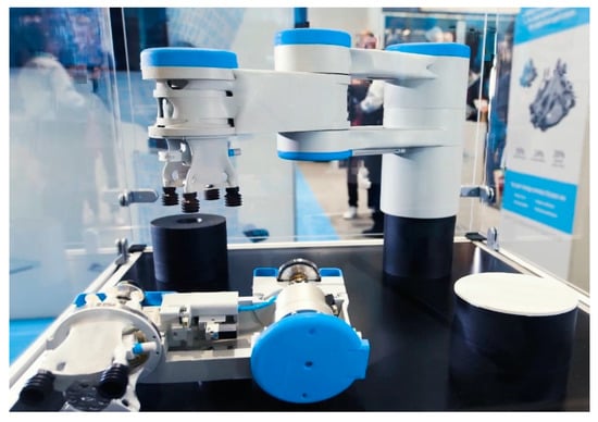
Figure 1.
Robotic system for researching the role of AM in future pneumatic lightweight robotics, as shown at the exhibition stand of Altair Engineering GmbH at the Formnext 2019 fair in Frankfurt (Germany).
Parallel publications deal with the development of AM RVAs [46], soft AM-based bellows actuators [45,47], and the robot’s gripper [44] with an integrated printed soft actuator.
1.7. Organization of This Paper
The main body of this paper is organized as shown in Figure 2. In Section 2, the kinematics and mechanical structure of our robot are introduced (Section 2.1), and the TO-based design is described along with a case study on manufacturing-related constraints (Section 2.2) and a validation experiment (Section 2.3). Section 3 presents the robot’s pneumatic system (Section 3.1), summarizes the development of additively manufactured soft bellows actuators and RVAs, compares both concepts (Section 3.2), and describes PJ-printed pneumatic valve modules (Section 3.3). Integration of the mechanical and pneumatic systems to form the final robot design is presented in Section 4.
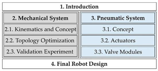
Figure 2.
The organization of this paper reflects the work packages during the development of the robot.
2. Mechanical System
The robot’s mechanical structure was developed following a simulation-driven design approach. This section describes the robot’s conceptual design (A), the TO of the robot’s structural parts, a case study of the effects of manufacturing-related optimization constraints (B), and a validation experiment (C).
2.1. Kinematics and Conceptual Design
We chose a kinematic type known as “SCARA”, which is an acronym for “Selective Compliance Assembly Robot Arm” [48]. SCARA kinematics are defined by a serial arrangement of three rotary and one linear joints and are typically used to automate assembly processes. Figure 3 shows a conceptual model of the robot; as shown in Figure 3A, we defined joint 2 as the linear joint, while joints 1, 3, and 4 are rotary. Links 2 and 3 provide center distances of 225 mm and 175 mm, respectively, which results in a workspace diameter of 800 mm, as illustrated in Figure 3B,C. Joint 2 enables 160 mm of vertical motion, as indicated in Figure 3B. As shown in Figure 3B, the main structural parts are the gripper and the three links. The second link, connecting joints 2 and 3, consists of separate top and bottom parts to ensure maximum stiffness of the structure. Except for link 1, which was realized by a standard automation component, optimal link shapes were obtained using the TO method described below. The design domains, that is, the regions that were later modified by the optimization algorithm, are indicated in brown.
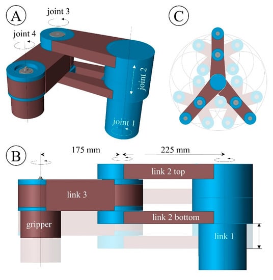
Figure 3.
Kinematics and conceptual design of an AM-based lightweight robot. The joint layout is shown in the three-dimensional (3D) view (A). Names of the main components and joint distances are given in the side view (B). The workspace dimensions are shown in the side (B) and top (C) views, respectively. The final shapes of the brown design domains were determined later by TO.
2.2. Topology Optimization
TO creates structures with an optimal material layout by reducing the FE mesh of a design domain to a fraction of its elements. As every element of the design domain is either a void or a structural member, the optimization problem is inherently discrete, and hundreds of thousands of variables may exist. Optimization problems of this type (discrete, large-scale) are difficult to solve, and the most widely used solution approach is to consider the element densities as continuously variable [5].
2.2.1. The Density Method
Here we recapitulate the basic equations of the “density method” [6,49], also known as SIMP (solid isotropic material with penalization). In the density method, continuous pseudo-element densities ρe (0 < ρe ≤ 1) are introduced, where a value of 0 corresponds to a void element and a value of 1 corresponds to an element filled with material. Coupling the element stiffnesses to their pseudo-densities yields
where and are the penalized and non-penalized element stiffness matrices, respectively. By introducing a penalization factor p > 1, intermediate densities become uneconomical, which means that the mass of an element is high compared to its penalized stiffness. This penalization drives the optimization result towards discrete topologies; most element densities are consequently close to 0 or 1. In many lightweight applications, such as the robot described, structural displacements are more critical than structural strength. This corresponds to the most common objective in structural TO, which is the minimization of structural compliance as a reciprocal measure of structural stiffness for a given amount of material. For FE simulations with multiple load cases i = 1 … n, the weighted sum of the compliances Cw(ρ) results from the individual load case compliances Ci (ρ) and weighting factors wi:
The stiffness matrix of the structure is assembled from the individual element stiffness matrices . Structural compliances, Ci(ρ), are typically defined as shown in Equation (2), with u being the displacement vector.
The minimum weighted compliance optimization problem is:
with Equation (4) expressing the equilibrium of static external (f) and internal forces and Equation (5) defining the value range for the design variables . The volume fraction constraint v constrains the volume occupied with material in the design space in relation to the total volume of the design space (Equation (6)). Universal constraint functions and can be formulated as shown in Equation (7) to influence the symmetry and manufacturability of the results. The solution to the problem results in most of the pseudo-element densities being near the lower or upper bounds. For further analysis and design finalization, elements with pseudo-densities above a threshold value are considered materials. Elements with densities below the threshold are omitted.
2.2.2. Simulation Model
To prepare for the TO of the robot’s structural parts, a suitable FE model was set up, which is shown in Figure 4. A configuration with joint 3 being 90° deflected was modeled in order to account for maximum torque loads. In the actual robot, joints 1 and 2 are stiff metallic parts and were thus represented by a fixed support in the FE model.
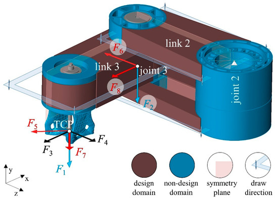
Figure 4.
FE model for TO of an AM-based lightweight robot. The structure is supported at joint 2, with loads attacking at the TCP and at the center of joint 3. Loads are grouped into three load cases (LCs) and marked accordingly in blue (LC1), black (LC2), and red (LC3). Design and non-design domains, as well as symmetry planes and draw directions of split-draw constraints, are indicated in the legend.
Connections between adjacent links were modeled using appropriate contact properties and deformable solid models of the bearing and pre-tensioning system that was later used in the robot. During operation, the masses of both the links and the handled objects impose loads on the robot’s structure. As shown in Figure 4, equivalent masses were located conservatively at the center of joint 3 and the tool center point (TCP). The TO of the gripper has already been described by Dämmer et al. [44], and the final gripper geometry was used in the optimization of the robot. Three load cases (LCs) were formulated: LC1 (F1, F2) takes into account the translational acceleration of the robot in the vertical direction; LC2 (F3, F4) the angular acceleration of joint 3 with joint 2 being fixed; and LC3 (F5, F6, F7, F8) the angular acceleration of joint 2 with joint 3 being fixed. The applied force magnitudes were derived under consideration of static gravitational, centrifugal, and inertial effects, assuming equivalent masses of 3 kg each. Force vectors (non-scale) are shown in Figure 4, and the exact force values are given in Table A1 in Appendix A. During optimization, each load case was weighted equally, i.e., w1, w2, w3 = 1. Design and non-design domains were discretized using linear tetrahedral elements with an edge length of 3 mm. A Young’s modulus of 1475 MPa and a Poisson’s ratio of 0.42 were obtained from uniaxial tensile experiments at a strain rate of 10−3 1/s and set for the polymeric parts. Altair Inspire software by Altair Engineering Inc. was used for pre- and post-processing.
2.2.3. Optimization Setup and Constraints
Symmetry constraints were applied in each optimization run, with the global y-z-plane and x-y-plane being defined as symmetry planes for links 2 and 3, respectively (see Figure 4). This was done to obtain symmetric results since the simulation model considered the deflection to one side only, as shown in Figure 4. Symmetry constraints couple the density values of opposing elements, the mathematical formulation of which was described by Zou et al. [6]. In four of six optimization runs, additional manufacturing-related constraints were introduced and their effects on the resulting topologies examined. To solve the TO problem stated in Equations (3)–(7), the Altair OptiStruct solver was used and accessed via Inspire software [49]. Draw direction constraints prevent the formation of cavities and undercuts with respect to an opening direction [49]. The split draw option—a sub-option of the draw direction constraint—implies that the optimized part can be molded with a mold that splits apart in the draw direction. The geometry of the splitting surface of the two mold halves is part of the optimization [49]. The mathematical formulation of the split draw constraint [6,7] prevents density values from increasing with increasing distance to the splitting surface. This avoids the formation of undercuts and non-demoldable holes, irrespective of the density threshold selected. As indicated in Figure 4, the y-direction was defined to be the draw direction of each design domain. Nevertheless, the optimization results may still have openings that penetrate the splitting surface, which would complicate the manufacturing of suitable molds. The “no hole” option in OptiStruct prevents low element densities in the splitting surface that may cause openings in the draw direction. Table 1 gives an overview of the six optimization runs performed and the constraints applied. The volume fraction constraints v alternated between 0.15 and 0.3.

Table 1.
A TO case study of an AM-based lightweight robot. Split draw, no hole, and volume fraction constraints were varied according to the table.
2.2.4. Optimization Results
Figure 5 shows 3D views and sectional views of the optimized structural concepts, based on which the effects of various constraints on the resulting topologies can be compared. Elements with pseudo-densities below 0.5 are masked out. Structural concepts 1, 3, and 5 are shown in the top row and were obtained from optimizations with a volume fraction constraint of v = 0.15, while the middle and bottom rows correspond to a volume fraction constraint of v = 0.3. Generally, combinations of the split draw and no hole constraints led to topologically similar structural concepts for both volume fractions, with the main difference being the size of individual features.
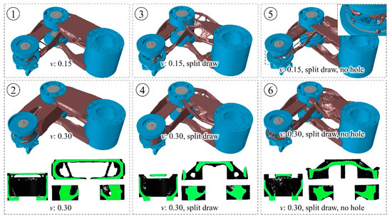
Figure 5.
Structural concepts of an AM-based lightweight robot. Volume-fraction constraints were applied that would allow utilization of 15% (top line) or 30% (middle and bottom line) of the design domains indicated in brown. Sectional views of structural concepts 2, 4, and 6 are presented to show undercuts and through holes, with the cut surfaces shown in green. The concepts resulted from TO runs without manufacturing-related constraints (concepts 1 and 2, left column), with split draw constraints (concepts 3 and 4, middle column), and with split draw and no hole constraints (concepts 5 and 6, right column).
In the absence of a split draw constraint, the algorithm “accumulated” material at the outer edges of the design domain of structural concepts 1 and 2, which resulted in structures with high torsional and bending stiffness. However, the extreme undercuts (visible in the sectional views) make demolding of these concepts impossible when a split mold is used. Imposing a split draw constraint resulted in structural concepts 3 and 4, which are shown in the middle column. Thin branches were formed to transmit bending and torsional loads, as a closed outer shell would contradict the imposed split draw constraint. Material accumulated towards joint 2, which is supported, reflecting the torque curve due to bending loads.
Molding of structural concepts 3 and 4 seems generally possible, as no undercuts exist in the draw direction. However, since there are many through holes, very complex-shaped molds would be required. Activation of the no hole option in addition to the split draw constraint yielded structural concepts 5 and 6, which are shown in the right column of Figure 5. Concept 6 is very similar to concept 4, but through holes are effectively closed by the no hole constraint. In concept 5, the top part of link 2 is almost flat, as the relatively small amount of material available was required to establish a closed connection between joints 2 and 3. The default settings in OptiStruct prohibit the formation of structural members smaller than three times the element size. Elements with intermediate densities appear as unclosed connections at link 3 in this illustration (magnified image).
In order to compare the maximum TCP displacements of the six optimized concepts, FE simulations were performed using the same load cases that had been used for optimization. Maximum TCP displacements were generally reached in LC3, and complete results for all load cases are provided in Table A2 in Appendix A. In Figure 6, the maximum TCP displacements of the six concepts are shown, and the effects of manufacturing-related constraints can be compared. In addition to the absolute TCP displacement values (in mm, left axis), relative maximum displacements (dimensionless, right axis) are given that relate the absolute values to displacements from simulations with the complete design domain shown in Figure 4. TCP displacements were between 0.73 mm (concept 2) and 1.53 mm (concept 5). The average maximum TCP displacement amounted to 0.78 mm for volume fraction constraints of 0.3, which is 43% less than the average maximum displacement of 1.37 mm with volume fraction constraints of 0.15. Note that the deformation of the non-design domain also contributes to the TCP displacement.
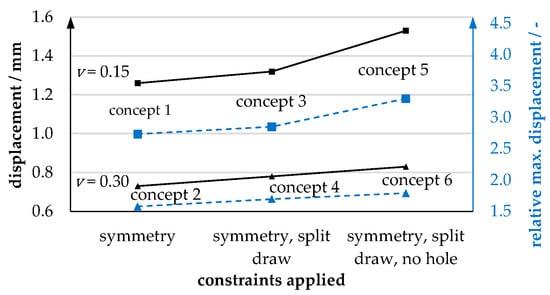
Figure 6.
TCP displacements of six different structural concepts for an AM-based robot. The concepts differ in the constraints (symmetry, split draw, no hole) applied to the underlying TO and the volume fractions used (15%; 30%). Maximum TCP displacements are given as absolute values (solid black curves) and relative to the complete design domain, corresponding to a volume fraction of 100% (dashed blue curves).
In run 6, the relative max. displacement was 1.79, which means that the structure deforms 1.79 times as much as the complete design domain. Run 2, in which the same volume fraction but no manufacturing-related constraints were applied, yielded a maximum relative TCP displacement of 0.158, which corresponds to a reduction of 12% or 0.1 mm compared to run 6. The reduction in structural stiffness due to imposing the no-hole constraint appears to be more pronounced at a volume fraction of 0.15 than of 0.3. As open connections occurred in concept 5, we repeated the optimization and analysis with an element size of 2 mm and adjusted the density limit, which slightly improved the results. However, intermediate densities in the optimization results contribute to the particularly large TCP displacement of concept 5.
Overall, the TO results are very plausible and agree with the theory derived in Section 2.2. Based on the example of a pneumatic lightweight robot, our results show that the introduction of manufacturing-related constraints effectively prevents the formation of undercuts and through holes, but at the expense of a decrease in structural stiffness. While these qualitative correlations can easily be derived from optimization theory, our results show their quantitative effects and practical relevance. In our example, the introduction of split draw and no hole constraints led to a 12% (0.1 mm) increase in the simulated maximum TCP displacement. We expect that this effect would be even more pronounced if the design domains were extended. Future work should also consider manufacturing costs, the properties of injection molding materials, and the potential for part consolidation by AM. The robot described provides the basis for these investigations. Concept 2 was pursued for further development.
2.3. Validation Experiment
To assess the general accuracy of our FE simulations, we manufactured link 3 using selective laser sintering (SLS) and conducted loading experiments. A single link was experimentally investigated instead of the complete multi-part structure to minimize the complex and unknown effects of pre-tension and friction at the joints. In the experimental setup, which is shown in Figure 7, the link was attached to a massive bracket that took the place of the third joint’s bearings. For load introduction, a circular steel plate was used, which acted as the upper ball bearing of the fourth joint. In the experiment, a linear actuator was velocity-controlled to extend at 0.01 mm/s, exerting a downward force on the link that was continuously measured by means of a load cell. Four consecutive runs were performed at forces of up to 30 N, 60 N, and more than 100 N (two runs). As shown in Figure 7, the measured displacement-force characteristics exhibit linear behavior for small displacements and become slightly degressive above about 0.3 mm of displacement. Up to the maximum values of the first and second runs, the differences between the four measurement curves were minor.
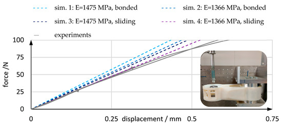
Figure 7.
Comparison of experiments (solid gray lines) and simulations (dashed colored lines) in terms of structural stiffness. In the experiments, the robot’s link 3 was subjected to an increasing load exerted by a velocity-controlled linear actuator, as shown in the small photograph. In the simulations, Young’s modulus and contact properties were varied.
An FE simulation model was set up in accordance with the experimental conditions, using quadratic tetrahedral elements with an average edge length of 3 mm. Young’s modulus and contact properties were varied to investigate their effects on the simulation results. We defined Young’s moduli of 1366 MPa and 1475 MPa, which we had obtained from uniaxial tensile experiments at strain rates of 10−4 1/s and 10−3 1/s, respectively. Our simulations show that both contact definitions and material parameters have a considerable effect on structural stiffness. At 0.4 mm displacement, simulations (sim.) predicted structural reaction forces between 76.2 N (sim. 4) and 92.2 N (sim. 1), which is between 5.1% and 27.2% more than the averaged experimental force of 72.5 N. Taking into account that neither the exact contact properties nor the exact complex strain-rate-dependent constitutive behavior of polyamide12 (PA12) were modeled in the simulation, we consider the results accurate. In the range of the forces applied during the optimization (below 61 N), the structural behavior was relatively linear and reversible and can thus be approximated by a linear elastic simulation.
3. Pneumatic System
While the previous section described the mechanical structure, this section covers the pneumatic system contained within the robot’s front end, including descriptions of the conceptual design of the pneumatic system (A), the development of AM-based pneumatic actuators (B), and the design of pneumatic valve modules (C).
3.1. Pneumatic System—Conceptual Design
Figure 8 shows a schematic diagram of the pneumatic system contained in the robot’s front end, where the main components are an air supply line, two valve modules, two pneumatic actuators for the actuation of joints 3 and 4, and a vacuum gripper. Each pneumatic actuator has two pressure chambers and connectors and creates torque if a differential pressure is applied. Valve modules are compact control units that use electrical signals to generate the desired actuator chamber pressures. Each joint-actuator pair is assigned to one valve module: joint 3 is controlled by valve module VMJ3 and joint 4 by valve module VMJ4.
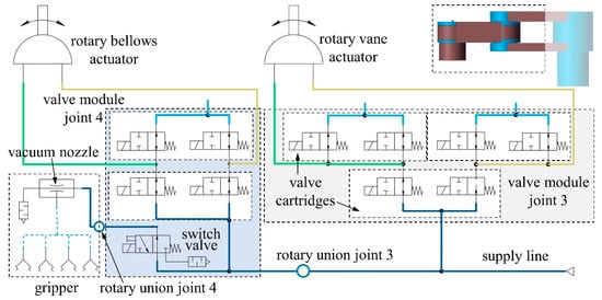
Figure 8.
Schematic illustration of the pneumatic system integrated within the front part of the robot. Two pneumatic valve modules containing piezo valve cartridges are used to control air flow to the rotary bellows and RVAs. A vacuum gripper with four suction cups contains a vacuum nozzle that is controlled by a switch valve.
Furthermore, each valve module is pneumatically connected to (i) the air supply line—in which supply pressure is always maintained; (ii) both chambers of a pneumatic actuator; and (iii) the environment. The valve modules contain several valve cartridges in which piezo actuators control the degree of opening and thus the flow rate through the valve ports. The cartridges each comprise two piezo actuators; thus, one cartridge resembles two two-way valves with one common port. In each valve module, one cartridge is connected to the supply pressure and used for pressurization. One (VMJ4) or two (VMJ3) cartridges are connected to ambient pressure and used for venting. The gripper contains a vacuum nozzle that utilizes the Venturi effect, that is, it generates a vacuum using a high-velocity air stream. Integrated within VMJ4 is a switch valve that can connect the vacuum nozzle to the supply line to evacuate the four suction cups of the gripper. In joints 3 and 4, air supply must be transferred between adjacent links, that is, members subject to relative motion. Using multiple valve modules instead of a central valve terminal simplifies this problem, as only a single supply pressure line must be fed through the joints and compact single-pass rotary unions can be used.
3.2. Pneumatic Actuators
In the course of robot development, AM-based RVAs and rotary bellows actuators were designed; since detailed descriptions of the actuators have already been published [45,47], this section provides only a brief summary of their development. As an extension to the previous publications, the actuator research is put into the context of robot development, and the soft and rigid actuator design concepts are compared critically with regard to future industrial applications. Integration within the final robot is shown in Section 4.
3.2.1. Integration of Rotary Bellows Actuator
In bellows actuators, actuation results from the expansion of a pressurized, deformable chamber. This actuation concept has become popular in research [34,35], as there are no special requirements for dimensional tolerances and surface smoothness, and thus direct AM is possible [36,38,39,40]. We developed a rotary multi-material bellows actuator to actuate the robot’s fourth joint and to act as a PolyJet technology demonstrator. Figure 9 gives an overview of the four stages of development.
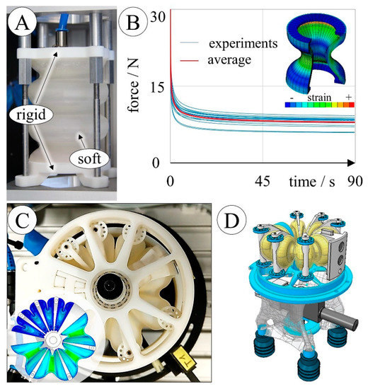
Figure 9.
Developing a PolyJet-printed rotary bellows actuator. Linear soft bellows actuators were used for preliminary investigations of material selection, bellows shape (A) [47], and time-dependent material behavior (B) [45]; research findings informed a rotary actuator design (C) [45] that contains two antagonistically arranged soft bellows chambers. The vacuum gripper (D) [44] that was later installed in the robot was obtained by combining the soft rotary bellows chambers with a rigid, lightweight structure.
For preliminary investigations, linear bellows actuators measuring 52 mm in length and 64 mm in diameter were produced using rigid Vero material [50] for the flanges and elastomeric materials (TB+, A30) for the soft bellows structures, as shown in Figure 9A. As part of a fatigue experiment, pressure cycles were run, which repeatedly expanded the actuators by 30 mm. Cycles to failure ranged from less than 20 for a TB+ bellows of a simple shape with constant wall thickness to more than 30,000 for an A30 bellows of a numerically optimized shape. For A30—the clearly superior material—numerical shape optimization increased the average fatigue life from 143 to 24,104 load cycles (according to three tests before and after optimization). Only A30 was considered for further development, and relaxation tests were performed using redesigned bellows structures, the results of which are shown in Figure 9B. The bellows structures, measuring 22 mm in length and 20 mm in diameter, were deflected by 4 mm within 0.5 s. Within 89.5 s of constant elongation, reaction forces decreased by 74%, with 70% of the relaxation occurring within the first 10 s, which demonstrates the time dependency of the mechanical behavior of A30 structures. Relaxation-test data were combined with uniaxial and planar tensile-test data to calibrate a hyperviscoelastic material model, which was in turn used for FE simulations of the experiments described above. Fine-tuning of the model parameters reduced the remaining differences between simulation and experiment to less than 2%.
In the next development step, a rotary bellows actuator was designed [45] with two antagonistically arranged bellows chambers, as shown in Figure 9C. The numerically optimized linear bellows shape [47] served as a template for the rotary bellows chamber shape and was refined by FE simulations. It has been shown that multi-material printing of A30, Vero materials, and a soluble support material enables the integration of the three main actuator components—housings, bellows chambers, and drive shaft—into a single part. Only a few additional parts, such as drive-shaft bearings and rollers that guide the bellows structure’s motion, are required to complete the assembly. The actuator measures 80 mm in diameter and 44 mm in height and weighs 105 g. At 90 mbar, angles of ±24° are approached, which can be further increased by applying higher pressures. We thus showed that using the provided hyperviscoelastic material model and considering frictional effects in the FE model allows the time-dependent behavior of the rotary bellows actuator to be estimated, which adds a practical example to the materials sciences of PolyJet elastomers. In the next development stage, the vacuum gripper shown in Figure 9D was obtained by combining the soft rotary pressure chambers and a topologically optimized lightweight structure with internal vacuum tubing. Integration of the gripper within the robot is shown in Section 4. Joint 4 contains annular grooves that prevent undesired shifting of the rollers. In the robot, VMJ4 is directly connected to the actuators’ pressure chambers by means of O-ring seals.
3.2.2. Integration of RVA
Pneumatic RVAs create torque if pressure differentials are applied to the two sides of a rotary vane inside a rigid housing. The main components, shown in Figure 10A,B, are the housings (top housings are not depicted), a drive shaft, the rotary vane, and a chamber seal that separates the housing volume into two distinct pressure chambers. Chamber seals and rotary vanes have rigid polymer cores with elastomer overmolds and are commercially manufactured by multi-step injection molding of highly resilient materials. To the best of our knowledge, AM of RVAs has previously been attempted only once [29]. In the course of robot development, we developed various AM-based replicas of a commercial RVA, two of which are shown in Figure 10. Unlike the bellows actuator development, RVA development was not limited to the use of a single technology, and technical performance was given priority over functional integration. Development, manufacturing, and testing of AM-based RVAs with polymeric housings, such as those shown in Figure 10A,C, were described in detail by Dämmer et al. [46]. Like the original RVA, the AM-based polymer replicas produce up to 5 Nm of drive torque over an angular range of 270°. At a mass of less than 226 g, the replicas weigh only about 52% of the commercial RVA (437 g), with the weight advantage resulting mainly from the use of redesigned polymer housings.
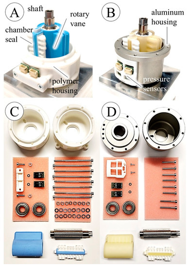
Figure 10.
AM-based rotary vane actuators for use in pneumatic lightweight robots in half-assembled (A,B) and fully disassembled (C,D) states. RVA with additively manufactured and machined polymer housings and polymeric seals with PA12 cores and blue SIL elastomer overmolds (A,C). RVA with machined aluminum housings and polymeric seals with PA12 cores and yellow PU elastomer overmolds (B,D). Overmolds were obtained using laser-sintered PA12 molds.
Using FE simulations, the standard housing geometry was modified to consider the lower stiffness and strength of the polymeric materials used. Housings were produced by SLS of PA12 and by PolyJet-printing of Vero material. Critical surfaces were printed with an oversize of 1 mm and then Computer Numerical Control (CNC)-machined to the final dimensions. The required multi-material seals were obtained using laser-sintered molds to overmold laser-sintered cores with either silicone (SIL) or polyurethane (PU) elastomers.
The quality of the replicas was then evaluated by repeatedly measuring leakage and friction properties and applying cyclic loads between measurements. Overall, RVAs with PU seals and PolyJet housings showed the best performance. They exhibited leakage flows of only 0.4–1.2 L/min between 0 and 10,000 load cycles, showed consistent frictional behavior similar to that of the standard RVA, and reached up to 1,000,000 load cycles without critical wear or structural failure. However, aluminum housings are used in the current version of the robot since development of the polymeric housings has only recently been completed. Figure 10B,D shows the RVA version with aluminum housings and seals consisting of laser-sintered PA12 cores with PU overmolds. This version has a mass of 263 g, and the integration within the lightweight robot is shown in Section 4. The aluminum housings are bolted to the bottom part of link 2. A PA12 sensor bracket holds two pressure sensors that measure the chamber pressures, and the torque is transmitted to the next link (link 4) by means of a toothed aluminum disc. Integrated air hoses connect the pressure chambers of the actuator to the valve module.
3.2.3. Comparison of AM-Based Actuators
Table 2 compares the main characteristics of the rotary bellows actuators and the RVAs. In summary, the rotary bellows actuators are research objects that demonstrate the capabilities and limitations of current PolyJet technology and are a practical example of state-of-the-art multi-material AM in robotics. The potential of multi-material AM is widely recognized in soft robotics: It may lead to completely new robotic designs—as formulated by Schmitt et al. [35]: “These methods may open new pathways for soft-rigid robotic systems, benefiting both from soft compliant elements and structural reinforcements, similar to what can be found in the nature”. However, exclusive use of PolyJet limits mechanical performance. In order to obtain actuators that fulfill their purpose at a competitive level in an industrial environment, the design described must be tested with more resilient materials as they become available in the future. Nevertheless, our investigations enable researchers to conduct FE simulations that consider the previously largely ignored time dependency of PolyJet elastomers and support conceptual benefits such as low friction and leakage and simplicity of manufacturing.
Table 2.
Purposes, technical properties, and conceptual differences between the AM-based actuators developed for a pneumatic lightweight robot.
Currently, the manufacturing of AM-based RVAs is cumbersome as it involves multiple steps and manual labor. However, combining AM with conventional technologies has, in this case, led to high-performance actuators that still allow relatively short iterations of design and testing as required in research and pre-development. The RVAs can be used for functional prototyping because their performance and behavior are very similar to those of commercial standard parts. The AM-based strategy for prototyping RVAs comprises only simple and accessible manufacturing methods. Overcoming the technological and economic constraints of mass production techniques, especially multi-step injection molding, creates the basis for low-cost prototyping and the development of application-specific RVAs with modified designs—an important contribution to the fields of printed robotics and pneumatic actuator prototyping.
3.3. Pneumatic Valve Modules
The main requirement imposed on the valve modules is that air flow to the actuator chambers can be controlled by means of electrical signals. The intended use of a functional research robot implies that repeated assembly and disassembly and hours of operation during laboratory tests and exhibitions must be withstood without structural failure or excessive leakage.
3.3.1. Mechanical Design and Manufacturing
The actuator chamber pressures can be adjusted by changing the opening cross-sections of the piezo cartridges that connect the supply line, the actuator chambers, and the environment. For this purpose, two valve modules, VMJ3 and VMJ4, were developed, whose pneumatic operating principles and circuitry were explained in Section 3.1. This section describes the mechanical design, CAD drawings of which are shown in Figure 11.
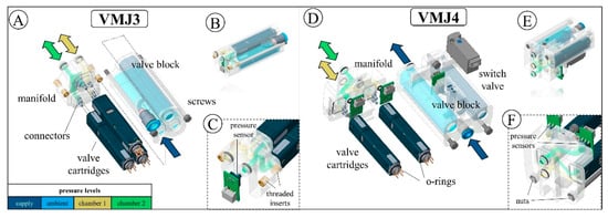
Figure 11.
PolyJet-printed valve modules for use in a pneumatic lightweight robot. Valve modules are shown in assembled (B,E) and disassembled states (A,D), and detailed views of the manifold blocks are shown (C,F). The pressure levels inside the valve blocks and manifold blocks are color-coded to be consistent with Figure 8.
VMJ4 is connected to the rotary bellows actuator sitting in joint 4, and VMJ3 is connected to the RVA sitting in joint 3. Each valve module comprises a valve block that encapsulates the valve cartridges and a manifold block that connects the connectors of the valve cartridges to the pressure chambers of the actuators. Each valve block contains two pressure chambers, with one chamber connected to supply pressure and the other vented to ambient pressure. The valve cartridges, which are normally used as a pilot stage in a commercial valve (VEVM, Festo SE & Co. KG, Esslingen, Germany), are sealed against the valve blocks by means of O-ring seals and connected to the manifold blocks by aluminum connectors. Openings in the cartridge bodies vent the cartridges to the pressure chambers of the valve blocks. As shown in Figure 11D, VMJ4 contains three sensors (Fujikura Ltd., Tokyo, Japan) for measuring the supply chamber pressures and an additional solenoid switch valve (MHA1, Festo SE & Co. KG, Esslingen, Germany) to activate air flow to the vacuum nozzle in the gripper. VMJ3 contains only a sensor for the supply pressure because chamber pressures are measured directly in the RVA housings, as shown in Figure 10. The valve blocks’ pressure chambers have a wall thickness of 2 mm. The pressure channel and connector diameters measure 3 mm.
The valve blocks and manifold blocks were manufactured by PolyJet printing of Vero material at cirp GmbH (Römerstraße 8, 71296 Heimsheim, Germany). Parts were printed with “glossy” surface finish, and circular features were oriented parallel to the printing plane. Prior to assembly, M2 nuts and threaded brass inserts were placed in the manifolds, as shown in Figure 11C,F, respectively. Turned aluminum connectors were glued into the manifolds. O-rings of sizes 2.5 × 1.0 mm2, 7.0 × 1.0 mm2, and 6.0 × 1.0 mm2 were placed on the pressure sensors, cartridges, and manifolds, respectively. The valve cartridges were attached to the connectors, and the valve blocks were connected using M2 screws.
3.3.2. Component Testing
Experiments were carried out prior to installation in the robot to ensure proper function and sealing of the valve modules. Figure 12 shows the experimental setup comprising VMJ3, an RVA (DRVS 25, Festo) of the same size as used in the robot, a connector dummy, and the joint electronics. Pressure sensors, a rotary encoder, and valves are connected to the electronic board. In this test, both valve modules were fully functional, enabling control of the RVA’s chamber pressures and position. Despite the successful functional test, long-term structural integrity and air tightness were of concern. Thus, VMJ3 was tested for structural integrity and air tightness under repeated loadings. For this purpose, the RVA was replaced by a 1-L buffer volume, and pressure was controlled externally by means of a proportional valve (MPYE, Festo SE & Co. KG, Esslingen, Germany). The piezo valve cartridges were completely opened, as no electrical voltage was applied. The valve module and buffer volume were pressurized for 10 s with 6 bar (relative) and then vented for 5 s before the cycle was repeated. Volume flow was measured with a flow sensor (SFAB-10, Festo SE & Co. KG, Esslingen, Germany) after 7 s of pressurization.
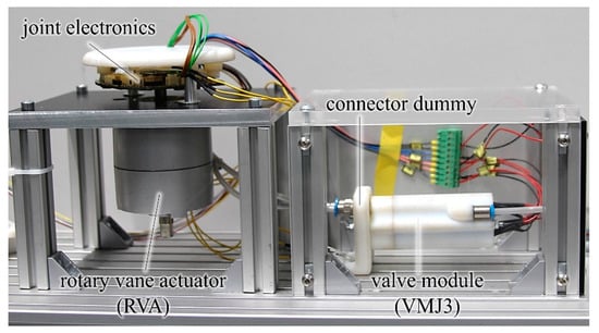
Figure 12.
Functional testing of a PolyJet-printed valve module. The experimental setup simulates the installation and operation of the actual robot and comprises the valve module, a connector dummy, joint electronics, and an RVA.
VMJ3 reached over 10,000 pressure cycles without violating the leakage criterion of 1.5 L/min or showing any signs of damage. The functional test and durability experiment show that our new valve modules are suitable for use in functional prototyping and product development. For further weight reduction, the valve cartridges could be integrated directly into the structural link components in the future.
4. Final Robot Design
The mechanical and pneumatic systems described in Section 2 and Section 3 established the basis for the final robot design. In this section, the integration of these subsystems is shown and complemented with remarks on the robot’s final design, pneumatic interfaces, electronics, and control. In Figure 13A, a sectional CAD drawing of the final robotic system is presented. The final structural component designs (i.e., links 2 and 3) were modeled based on topology concept 2 using Inspire “PolyNurbs”, a surface modeling tool that utilizes Non-Uniform Rational B-Splines (NURBS). Structural parts were then obtained by SLS of PA12. The robot’s rotatable links are connected using adjusted bearing assemblies that can be pre-tensioned to prevent any play and compensate for relaxation of the polymeric material.
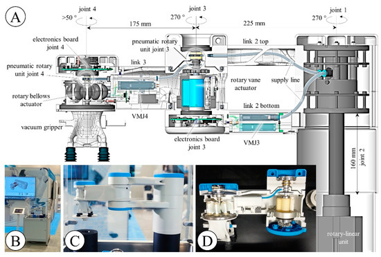
Figure 13.
AM-based pneumatically actuated lightweight robot with articulated joints. (A): Sectional view of the robot’s CAD model showing the joints, links, actuators, valve modules, and other components. (B): Exhibition demonstrator containing the functional robot at the exhibition stand of Altair Engineering GmbH at the Formnext 2019 international fair for AM in Frankfurt (Germany). (C): Close-up view showing the robot picking up a workpiece. (D): Close-up view of a cutaway model that was part of the exhibition demonstrator.
Joints 1 and 2 are realized by a pneumatic rotary-linear unit that comprises an RVA with an angular range of 270° and a double-acting pneumatic cylinder with a linear range of 160 mm. Supply pressure is led through the hollow shaft of the rotary-linear unit and divided into two branches. Using pneumatic tubes, the first and second branches are connected to VMJ3 and joint 3, respectively. Joint 3 contains a single-passage rotary union that connects supply pressure to link 3, which is in turn connected to VMJ4. Joint 4 contains a rotary union and a hollow shaft to realize a rotatable connection between VMJ4 and the venturi nozzle inside the vacuum gripper.
Power cables are routed through the robot together with a Controller Area Network (CAN bus) cable (not shown) and connected to the electronic boards of joints 3 and 4. Using a bus system minimizes the cables required for communication and is hence an industry standard in robotic manipulators. Each rotary joint is equipped with an inductive rotary encoder (Haidenhain EBI 1135; Dr. Johannes Haidenhain GmbH, Traunreut, Germany). The position of the linear joint is measured by means of a linear position transmitter (SDAP-MHS-M160; Festo SE & Co. KG, Esslingen, Germany). Model-based feedback controllers with cascaded position and pressure control were implemented. The code for pressure and position control of joints 3 and 4 is run on the joint electronics and a CPX-E automation system (Festo), respectively, and communication between the joint electronics and CPX-E is by CAN bus. The rotary-linear unit, comprising joints 1 and 2, is controlled by a Festo VTEM valve terminal.
Using the components described, an exhibition demonstrator was built to show the robot in operation. As illustrated in Figure 13B, the bottom of the demonstrator is a closed box that contains a pneumatic maintenance unit, a CPX-E, and a valve terminal. Pressing a button at the demonstrator’s front starts a motion sequence in which the robot transports a disc from one table to another. Figure 13C,D show a close-up of the robot picking up the disc and a cutaway model that was part of the demonstrator, respectively. The fully functional exhibition demonstrator as shown in Figure 13B–D was presented to the public at the HMI 2019 (Festo stand) and Formnext 2019 (Altair stand) exhibitions and the opening event of the Open Innovation Center (Johannes Kepler University Linz, June 2019). The presentation of a preliminary version of the robot, the DIMAP demonstrator, at Formnext2018 (cirp GmbH stand) led to the continuation of research work and cooperation.
In summary, substantial progress has been made towards the long-term objective of realizing additively manufactured pneumatic lightweight robots with articulated joints. The cutaway model in Figure 13D and the sectional view in Figure 13A show that a high proportion of additively manufactured components have already been realized, including newly developed rotary bellows actuators, RVAs, and valve modules, which proves that polymer AM is suitable for more than simple and mechanically less stressed components. Completely integrating the valve modules and tubing into the link structures and using the RVA fabrication methods to replace the rotary-linear unit would further increase both the proportion of AM components and the degree of functional integration.
5. Conclusions
The research work described here is a foray into the largely unexplored field of additively manufactured lightweight robots with pneumatically actuated rotary joints. We have presented the first functional robot of this type along with detailed descriptions of its structural parts, soft and rigid pneumatic actuators, and pneumatic valve modules. Comprising one translational and three rotary joints, the robot can handle objects of up to 1.5 kg within an approximately cylindrical workspace that measures 800 mm in diameter and 160 mm in height. Structural parts were developed using TO. This practical example shows that, for a given material, the capability of AM to produce very complex structures and undercuts can indeed be exploited to improve structural stiffness at a relevant magnitude if compared to injection-moldable structures. For example, in the absence of split draw and no hole constraints that prevented the formation of undercuts and through holes, the simulated maximum TCP displacement was by 12%, or 0.1 mm, smaller than in simulations with both constraints applied (v = 0.3).
Detailed descriptions of the RVA and rotary bellows actuators that actuate joints 3 and 4, respectively, have been published by Dämmer et al. [45,46]. This paper shows the integration of both actuators within an industry-like robot, along with a brief summary of their development and a comparison of design concepts considering future industrial applications. The RVA was manufactured using a combination of PJ/SLS, elastomer molding, and conventional CNC milling. As experimental investigations by Dämmer et al. [46] have revealed, these actuators are suitable for extensive functional prototyping. The AM-based RVAs can reach maximum torques of 5 Nm over an angular range of 270° and endure up to 1,000,000 load cycles. The rotary bellows actuator and lightweight structure of the gripper are combined into one multi-material component, obtained by parallel PolyJet printing of thermosetting rigid and soft elastomeric acrylate-based photopolymers. Since the bellows actuators provide only 20 Nmm of torque and an actuation range of about 50° at a pressure of 90 mbar, their materials require substantial enhancement to reach competitive levels of performance. However, the bellows actuator and gripper are examples of extreme functional integration by MM AM, require minimum assembly, and were utilized for basic research in the materials science of PolyJet elastomers. The conceptual advantages, like minimum friction and leakage, may be exploited using more resilient materials in the future.
Supply pressure tubing is routed through the robot using a combination of standard parts and printed components. Pneumatic valve modules and control electronics are integrated in each joint and convert electrical signals received via the CAN bus system to the desired actuator pressures. The valve modules comprise piezo valve cartridges, pressure sensors, and PolyJet-printed structural parts with integrated pneumatic tubing. Pneumatic connection to the robotic links is realized via piston-type O-ring seals. To investigate the durability of our valve modules, more than 10,000 pressure cycles of 6 bar relative pressure were applied, and no structural failure or relevant leakage was observed. The PolyJet-printed valve modules were described in detail so that researchers could adapt and customize the design according to their requirements.
While many publications have separately addressed TO, AM of robotic components, integrated fluidic systems, and fluidic actuators, we have drawn on all of these fields to make a functional industry-like robot and thus a substantial step towards additively manufactured, pneumatically actuated lightweight robots with articulated joints. Our work applies methods that are typically used in soft robotics, such as MM PolyJet printing and elastomer molding with additively manufactured molds, to the prototyping of the more widely used articulated robots. However, many challenges must be overcome, such as the development of highly resilient elastomers for multi-material AM, before commercialization and industrial use of such robots become realistic.
Author Contributions
Conceptualization, G.D., R.N. and Z.M.; Funding acquisition, R.N. and Z.M.; Investigation, G.D. and S.G.; Methodology, G.D.; Project administration, G.D.; Software, G.D.; Supervision, G.D., R.N. and Z.M.; Writing—original draft, G.D.; Writing—review and editing, S.G. All authors have read and agreed to the published version of the manuscript.
Funding
The authors are thankful for the opportunity to be involved in the DIMAP project, funded as part of the Horizon 2020 Framework program for research and innovation under grant agreement no. 685937. The funding received contributed considerably to the success of the work described.
Institutional Review Board Statement
Not applicable.
Informed Consent Statement
Not applicable.
Data Availability Statement
Data is contained within the article, Appendix A or cited articles.
Acknowledgments
We express our special thanks to cirp GmbH and Stratasys Ltd. for the manufacturing of PolyJet parts and Altair Engineering GmbH for providing optimization software. Further, we thank Sonja Laicher, Andreas Gause, Florian Haizmann, and Michael Lackner, who contributed to the project.
Conflicts of Interest
Gabriel Dämmer, Sven Gablenz and Rüdiger Neumann were employed by Festo SE & Co. KG, Esslingen, Germany.
Appendix A
Table A1.
Load cases for TO of an AM-based lightweight robot. Eight loads were applied in three load cases, and the vector components are given with respect to the coordinate system shown in Figure 4.
Table A1.
Load cases for TO of an AM-based lightweight robot. Eight loads were applied in three load cases, and the vector components are given with respect to the coordinate system shown in Figure 4.
| Load Case 1 | Load Case 2 | Load Case 3 | ||||||
|---|---|---|---|---|---|---|---|---|
| F1/N | F2/N | F3/N | F4/N | F5/N | F6/N | F7/N | F8/N | |
| x | 0 | 0 | −46.8 | 0 | −60.1 | 0 | −12.7 | −12.7 |
| y | −31.4 | −31.4 | 0 | 0 | 0 | 0 | 0 | 0 |
| z | 0 | 0 | 0 | 19.8 | −46.8 | −60.1 | −9.9 | 0 |
Table A2.
Results of a TO case study using an AM-based lightweight robot. Six TO runs were performed applying various combinations of the following constraints: split draw (yes/no), no hole (yes/no), and volume fraction (0.150/0.300). Analysis runs were subsequently performed to compare the TCP displacements of the optimized structures (1–6) to those with the design domain filled (structure 7) and final components (run 8). Structure 8 is of similar topology as structure 2, but was finalized using NURBS-based surface modeling, which caused an increase in volume and stiffness. Relative compliance values were obtained by dividing the compliances of the optimized structures by the compliance of run 7. The actual volume fractions of the components and the number of solver iterations required are given.
| Structure | Constraints | Actual Volume Fraction | Relative Compliance | Relative Max. TCP Displacement | TCP Displacement/mm | Solver Iterations | ||||
|---|---|---|---|---|---|---|---|---|---|---|
| Split Draw | No Hole | Volume Fraction | LC1 | LC2 | LC3 | |||||
| 1 | no | no | 0.150 | 0.137 | 3.80 | 2.73 | 1.04 | 0.69 | 1.26 | 33 |
| 2 | no | no | 0.300 | 0.300 | 1.90 | 1.58 | 0.52 | 0.40 | 0.73 | 24 |
| 3 | yes | no | 0.150 | 0.135 | 3.81 | 2.85 | 1.08 | 0.72 | 1.32 | 33 |
| 4 | yes | no | 0.300 | 0.294 | 1.94 | 1.70 | 0.55 | 0.43 | 0.78 | 28 |
| 5 | yes | yes | 0.150 | 0.165 | 4.62 | 3.30 | 1.18 | 0.81 | 1.53 | 50 |
| 6 | yes | yes | 0.300 | 0.295 | 2.09 | 1.79 | 0.57 | 0.45 | 0.83 | 36 |
| 7 | - | - | - | 1.000 | 1.00 | 1.00 | 0.25 | 0.25 | 0.46 | - |
| 8 | - | - | - | 0.437 | 1.29 | 1.36 | 0.39 | 0.34 | 0.63 | - |
References
- Gealy, D.V.; McKinley, S.; Yi, B.; Wu, P.; Downey, P.R.; Balke, G.; Zhao, A.; Guo, M.; Thomasson, R.; Sinclair, A.; et al. Quasi-direct drive for low-cost compliant robotic manipulation. In Proceedings of the 2019 International Conference on Robotics and Automation (ICRA), Montreal, QC, Canada, 20–24 May 2019; pp. 437–443. [Google Scholar] [CrossRef]
- Sariyildiz, E.; Mutlu, R.; Roberts, J.; Kuo, C.-H.; Ugurlu, B. Design and Control of a Novel Variable Stiffness Series Elastic Actuator. IEEE/ASME Trans. Mechatron. 2023, 28, 1534–1545. [Google Scholar] [CrossRef]
- Covestro, A.G. Effective Shoe Manufacturing with 3D Printing. 2019. Available online: https://www.covestro.com/press/effective-shoe-manufacturing-with-3D-printing/ (accessed on 25 June 2023).
- Mahle GmbH. MAHLE Produces High-Performance Aluminum Pistons Using 3D Printing for the First Time. 2020. Available online: https://www.jp.mahle.com/global/media/global_news/2020/07-additive_manufacturing/press_release_mahle-additive_manufacturing.pdf (accessed on 25 June 2023).
- Bendsøe, M.P.; Sigmund, O. Topology Optimization: Theory, Methods, and Applications; Springer Science + Business Media: Norwell, MA, USA, 2013; ISBN 978-3-662-05086-6. [Google Scholar] [CrossRef]
- Zuo, K.-T.; Chen, L.-P.; Zhang, Y.-Q.; Yang, J. Manufacturing-and machining-based topology optimization. Int. J. Adv. Manuf. Technol. 2006, 27, 531–536. [Google Scholar] [CrossRef]
- Mantovani, S.; Presti, I.L.; Cavazzoni, L.; Baldini, A. Influence of manufacturing constraints on the topology optimization of an automotive dashboard. Procedia Manuf. 2017, 11, 1700–1708. [Google Scholar] [CrossRef]
- Liu, J.; Ma, Y. A survey of manufacturing oriented topology optimization methods. Adv. Eng. Softw. 2016, 100, 161–175. [Google Scholar] [CrossRef]
- Liu, J.; Gaynor, A.T.; Chen, S.; Kang, Z.; Suresh, K.; Takezawa, A.; Li, L.; Kato, J.; Tang, J.; Wang, C.C.L.; et al. Current and future trends in topology optimization for additive manufacturing. Struct. Multidiscip. Optim. 2018, 57, 2457–2483. [Google Scholar] [CrossRef]
- Zegard, T.; Paulino, G.H. Bridging topology optimization and additive manufacturing. Struct. Multidiscip. Optim. 2016, 53, 175–192. [Google Scholar] [CrossRef]
- Sun, Y.; Liu, Y.; Pancheri, F.; Lueth, T.C. Larg: A lightweight robotic gripper with 3-D topology optimized adaptive fingers. IEEE/ASME Trans. Mechatron. 2022, 27, 2026–2034. [Google Scholar] [CrossRef]
- Kohn, R.V.; Strang, G. Optimal design and relaxation of variational problems, I. Commun. Pure Appl. Math. 1986, 39, 113–137. [Google Scholar] [CrossRef]
- Bendsøe, M.P. Optimal Shape Design as a material distribution Problem. Struct. Multidiscip. Optim. 1989, 1, 193–202. [Google Scholar] [CrossRef]
- Junk, S.; Klerch, B.; Nasdala, L.; Hochberg, U. Topology optimization for additive manufacturing using a component of a humanoid robot. In Proceedings of the 28th CIRP Design Conference, Nantes, France, 23–25 May 2018; pp. 102–107. [Google Scholar] [CrossRef]
- Grzesiak, A.; Becker, R.; Verl, A. The bionic handling assistant: A success story of additive manufacturing. Assem. Autom. 2011, 31, 329–333. [Google Scholar] [CrossRef]
- Richardson, B.S.; Lind, R.F.; Lloyd, P.D.; Noakes, M.W.; Love, L.J.; Post, B.K. The design of an additive manufactured dual arm manipulator system. Addit. Manuf. 2018, 24, 467–478. [Google Scholar] [CrossRef]
- MacCurdy, R.; Katzschmann, R.; Youbin, K.; Rus, D. Printable hydraulics: A method for fabricating robots by 3D co-printing solids and liquids. In Proceedings of the 2016 IEEE International Conference on Robotics and Automation (ICRA), Stockholm, Sweden, 9 June 2016. [Google Scholar] [CrossRef]
- Mazzolai, B.; Mattoli, V. Robotics: Generation soft. Nature 2016, 536, 400–401. [Google Scholar] [CrossRef] [PubMed]
- Sochol, R.D.; Sweet, E.; Glick, C.C.; Venkatesh, S.; Avetisyan, A.; Ekman, K.F.; Raulinaitis, A.; Tsai, A.; Wienkers, A.; Korner, K.; et al. 3D printed microfluidic circuitry via multijet-based additive manufacturing. Lab A Chip 2016, 16, 668–678. [Google Scholar] [CrossRef] [PubMed]
- Barasuol, V.; Villarreal-Magaña, O.A.; Sangiah, D.; Frigerio, M.; Baker, M.; Morgan, R.; Medrano-Cerda, G.A.; Caldwell, D.G.; Semini, C. Highly-integrated hydraulic smart actuators and smart manifolds for high-bandwidth force control. Front. Robot. AI 2018, 5, 51. [Google Scholar] [CrossRef] [PubMed]
- Diegel, O.; Schutte, J.; Ferreira, A.; Chan, Y.L. Design for additive manufacturing process for a lightweight hydraulic manifold. Addit. Manuf. 2020, 36, 101446. [Google Scholar] [CrossRef]
- Zhang, C.; Wang, S.; Li, J.; Zhu, Y.; Peng, T.; Yang, H. Additive manufacturing of products with functional fluid channels: A review. Addit. Manuf. 2020, 36, 101490. [Google Scholar] [CrossRef]
- Li, I.-H.; Lin, Y.-S.; Lee, L.-W.; Lin, W.-T. Design, manufacturing, and control of a pneumatic-driven passive robotic gait training system for muscle-weakness in a lower limb. Sensors 2021, 21, 6709. [Google Scholar] [CrossRef]
- Chiou, S.-J.; Chu, H.-R.; Li, I.-H.; Lee, L.-W. A Novel Wearable Upper-Limb Rehabilitation Assistance Exoskeleton System Driven by Fluidic Muscle Actuators. Electronics 2022, 12, 196. [Google Scholar] [CrossRef]
- Gaiser, I.; Wiegand, R.; Ivlev, O.; Andres, A.; Breitwieser, H.; Schulz, S.; Bretthauer, G. Compliant Robotics and Automation with Flexible Fluidic Actuators and Inflatable Structures; InTech Open Access Publisher: Rijeka, Croatia, 2012. [Google Scholar] [CrossRef]
- Festo AG & Co. KG. BionicCobot—Sensitive Helper for Human-Robot Collaboration. 2017. Available online: https://www.festo.com/net/SupportPortal/Files/462251/Festo_BionicCobot_en.pdf (accessed on 25 June 2023).
- Krause, J.; Bhounsule, P. A 3D printed linear pneumatic actuator for position, force and impedance control. Actuators 2018, 7, 24. [Google Scholar] [CrossRef]
- Varga, M.; Filakovsky, F. Design, manufacturing and problem analysis of an entirely FDM 3D printed linear pneumatic actuator. Tech. Sci. Technol. 2020, 3, 98–105. [Google Scholar] [CrossRef]
- Remmers, R.; Cook, D.; Gervasi, V. Custom, integrated, pneumatic, rotary actuator for an active ankle-foot orthosis. In Proceedings of the 2010 SFF Symposium, Austin, TX, USA, 9–11 August 2010; pp. 816–827. [Google Scholar]
- Siegfarth, M.; Pusch, T.P.; Pfeil, A.; Renaud, P.; Stallkamp, J. Multi-material 3D printed hydraulic actuator for medical robots. Rapid Prototyp. J. 2020, 26, 1019–1026. [Google Scholar] [CrossRef]
- Neitzert, T.R. Accuracy of Additive Manufactured Parts. Key Eng. Mater. 2015, 661, 113–118. [Google Scholar] [CrossRef]
- Rebong, R.E.; Stewart, K.T.; Utreja, A.; Ghoneima, A.A. Accuracy of three-dimensional dental resin models created by fused deposition modeling, stereolithography, and Polyjet prototype technologies: A comparative study. Angle Orthod. 2018, 88, 363–369. [Google Scholar] [CrossRef] [PubMed]
- Walker, J.; Zidek, T.; Harbel, C.; Yoon, S.; Strickland, F.S.; Kumar, S.; Shin, M. Soft robotics: A review of recent developments of pneumatic soft actuators. Actuators 2020, 9, 3. [Google Scholar] [CrossRef]
- Gorissen, B.; Reynaerts, D.; Konishi, S.; Yoshida, K.; Kim, J.-W.; De Volder, M. Elastic inflatable actuators for soft robotic applications. Adv. Mater. 2017, 29, 1604977. [Google Scholar] [CrossRef] [PubMed]
- Schmitt, F.; Piccin, O.; Barb, L.; Laurent, B. Soft robots manufacturing: A review. Front. Robot. AI 2018, 5, 84. [Google Scholar] [CrossRef]
- Wallin, T.J.; Pikul, J.; Shepherd, R.F. 3D printing of soft robotic systems. Nat. Rev. Mater. 2018, 3, 84–100. [Google Scholar] [CrossRef]
- Hu, W.; Mutlu, R.; Li, W.; Alici, G. A structural optimisation method for a soft pneumatic actuator. Robotics 2018, 7, 24. [Google Scholar] [CrossRef]
- Yap, Y.L.; Sing, S.L.; Swee Yeong, W.Y. A review of 3D printing processes and materials for soft robotics. Rapid Prototyp. J. 2020, 26, 1345–1361. [Google Scholar] [CrossRef]
- Zolfagharian, A.; Kouzani, A.Z.; Khoo, S.Y.; Moghadam, A.A.A.; Gibson, I.; Kaynak, A. Evolution of 3D printed soft actuators. Sens. Actuators A Phys. 2016, 250, 258–272. [Google Scholar] [CrossRef]
- Gul, J.Z.; Sajid, M.; Rehman, M.M.; Siddiqui, G.U.; Shah, I.; Kim, K.-H.; Lee, J.-W.; Choi, K.H. 3D printing for soft robotics—A review. Sci. Technol. Adv. Mater. 2018, 19, 243–262. [Google Scholar] [CrossRef]
- Polygerinos, P.; Correll, N.; Morin, S.A.; Mosadegh, B.; Onal, C.D.; Petersen, K.; Cianchetti, M.; Tolley, M.T.; Shepherd, R.F. Soft Robotics: Review of Fluid-Driven Intrinsically Soft Devices; Manufacturing, Sensing, Control, and Applications in Human-Robot Interaction. Adv. Eng. Mater. 2017, 19, 1700016. [Google Scholar] [CrossRef]
- Liu, C.-H.; Chen, L.-J.; Chi, J.-C.; Wu, J.-Y. Topology optimization design and experiment of a soft pneumatic bending actuator for grasping applications. IEEE Robot. Autom. Lett. 2022, 7, 2086–2093. [Google Scholar] [CrossRef]
- Kaminski, R.; Knubben, E.M. Fluid-Actuated Rotary Drive. European Patent Application 619 EP 2 497 959 A1, 12 September 2012. [Google Scholar]
- Dämmer, G.; Gablenz, S.; Hildebrandt, A.; Major, Z. Design of an Additively Manufacturable Multi-Material Light-Weight Gripper with integrated Bellows Actuators. Adv. Sci. Technol. Eng. Syst. J. 2019, 4, 23–33. [Google Scholar] [CrossRef]
- Dämmer, G.; Lackner, M.; Laicher, S.; Neumann, R.; Major, Z. Design of an Inkjet-Printed Rotary Bellows Actuator and Simulation of its Time-Dependent Deformation Behavior. Front. Robot. AI 2021, 8, 663158. [Google Scholar] [CrossRef]
- Dämmer, G.; Bauer, H.; Neumann, R.; Major, Z. Design, Additive Manufacturing and Component Testing of Pneumatic Rotary Vane Actuators for Lightweight Robots. Rapid Prototyp. J. 2021, 28, 20–32. [Google Scholar] [CrossRef]
- Dämmer, G.; Gablenz, S.; Hildebrandt, A.; Major, Z. PolyJet-Printed Bellows Actuators: Design, Structural Optimization and Experimental Investigation. Front. Robot. AI 2019, 6, 34. [Google Scholar] [CrossRef]
- Makino, H.; Furuya, N. Selective compliance assembly robot arm. In Proceedings of the First International Conference on Assembly Automation (ICAA), Brighton, England, 25–27 March 1980; pp. 77–86. [Google Scholar]
- OptiStruct, Altair. OptiStruct 11.0 User Manual; Altair Engineering Inc.: Troy, MI, USA, 2011. [Google Scholar]
- Stratasys Ltd. PolyJet Materials Data Sheet. 2018. Available online: https://www.cirp.de/verfahren/Materialdaten/PolyJet-Materials-Data-Sheet.pdf (accessed on 25 June 2023).


Disclaimer/Publisher’s Note: The statements, opinions and data contained in all publications are solely those of the individual author(s) and contributor(s) and not of MDPI and/or the editor(s). MDPI and/or the editor(s) disclaim responsibility for any injury to people or property resulting from any ideas, methods, instructions or products referred to in the content. |
© 2023 by the authors. Licensee MDPI, Basel, Switzerland. This article is an open access article distributed under the terms and conditions of the Creative Commons Attribution (CC BY) license (https://creativecommons.org/licenses/by/4.0/).