1. Introduction
Low-speed doubly salient permanent magnet (LS–DSPM) machines can be suitable for naval propulsion, wind energy, marine energy, new hybrid energy vehicles, and other fields thanks to the simplicity of their structure, low cost, high level of reliability, low-speed operation capability and maintenance-free operation [
1,
2,
3,
4,
5,
6,
7,
8,
9,
10]. However, the nonlinear electromagnetic characteristics of this structure lead to a large torque ripple. This is why torque ripple reduction has been one of the focuses of research in recent years. The proposed solutions are based on:
- -
Advanced control technique, which consists of applying indirect torque control [
11,
12,
13,
14,
15,
16,
17,
18,
19].
- -
The second solution to improve the torque ripple consists in modifying the geometry parameters of the conventional structures and optimizing the design of unconventional ones [
1,
2,
3,
4,
5,
6,
7,
8,
9,
10]. In [
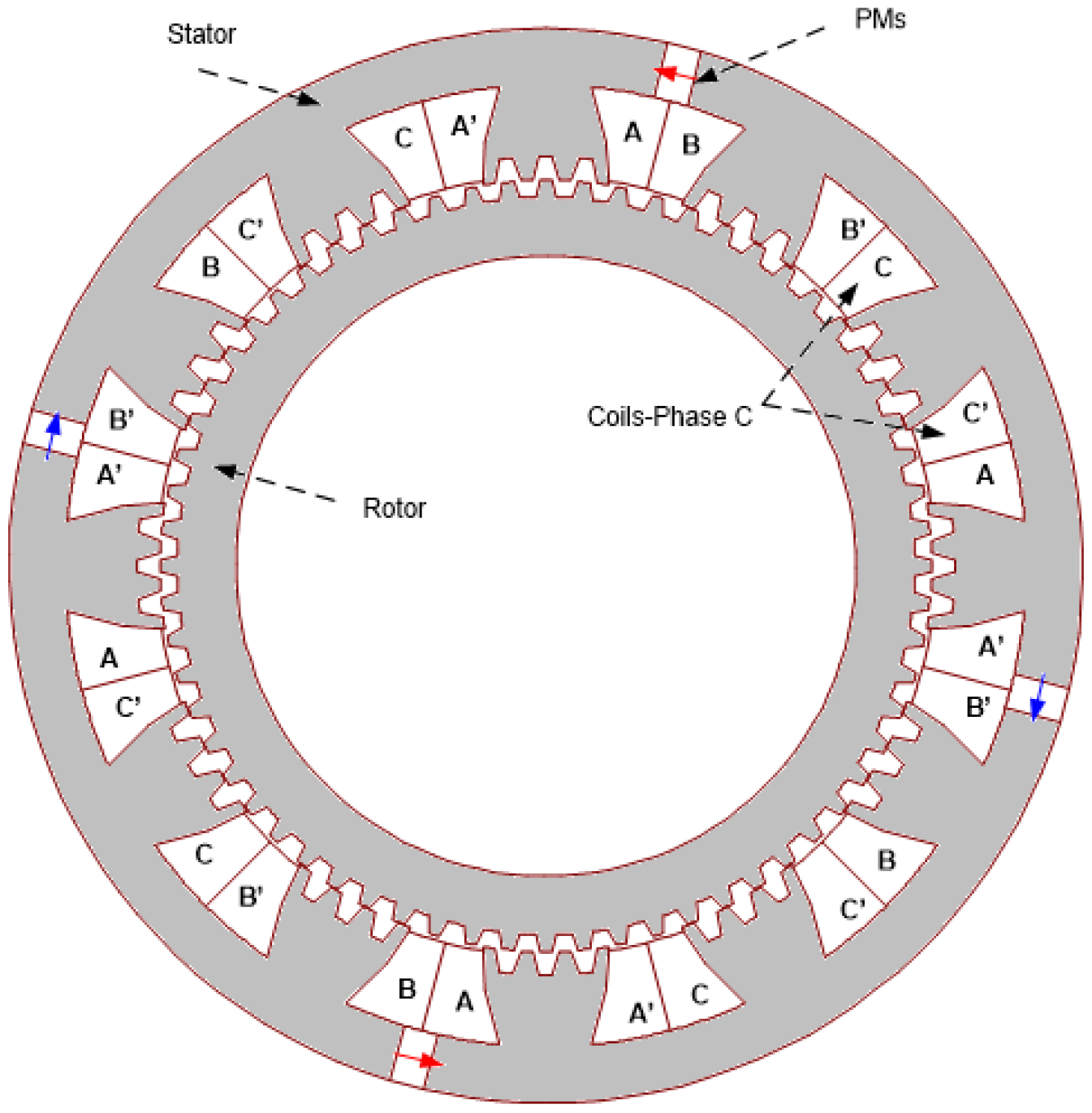
1], the design optimization and comparison of two synchronous structures operating at low speed, which have PMs in the stator, are achieved. It has been shown that introducing permanent magnets (PMs) in variable reluctance machines (
Figure 1) can improve output torque. In [
2], a novel structure is proposed to reduce the cogging torque and the mutual inductance. In [
3], two LS–DSPM machines with and without the Vernier effect were designed and optimized using genetic algorithms. The results reveal that the introduction of the Vernier effect principle in the LS–DSPM machines ameliorates the EMF form and reduces torque ripple. In [
4], the study of the forms and dimensions of the teeth that minimize torque ripple is presented. In [
5,
6,
11], it is demonstrated that the number of PM pairs and their location in the stator, the number of poles, the phase number, and the combination of the stator/rotor teeth numbers are parameters that influence strongly the machine performance and more specifically the torque ripple.
The work presented in this paper is based on the structure studied in [
1,
9]. In this structure, PMs are mounted in the stator, and the windings are located around salient stator poles, which have small teeth. The rotor does not include windings or PMs and has small teeth like the ones located on the stator poles. The absence of a PM or winding in the rotor causes a component of the reluctance torque, which is due to the variation of the reluctance. The air gap variation is due to the saliency of the stator/rotor core, which is considered one of the major drawbacks of this machine because it leads to the production of a wavy total torque (sum of reluctance torque and hybrid torque). Additionally, the PM’s location in this structure causes a slight asymmetry between the phase electromagnetic force (EMF) of phase one and the corresponding ones of the two other phases. This asymmetry is due to the fact that the magnet position in the stator yoke is not magnetically equivalent for all three phases. This asymmetry contributes also to torque ripple. Another source of torque ripple in this structure is due to its supply mode. The machine is generally powered by pulsed currents, which are applied to the machine during the rise or fall of inductance/PM flux. This mode of supply leads to high torque peaks during switching.
The proposed solution to reduce the ripple torque consists, in the first part, of improving the electromagnetic design of the studied structure. This design improvement is based on two principles. Acting on location of the permanent magnets allows eliminating the asymmetry between the three phases’ EMF voltage. Acting on the stator and rotor tooth pitch reduces the saliency effects on torque ripples.
The second part of the proposed solution is to apply a new control approach that is related to the switching region, which leads to a smooth output torque.
In the first part of this paper, the machines studied and the design optimization is presented. Two-dimensional FEM simulations were used in this design phase. Magnetic flux density distribution, flux lines and curves, back–EMF, magnetic flux, and torque curve network were examined. Secondly, the reduction of the ripple torque of the optimal machine by the TSF control technique was examined. MATLAB/Simulink software was used to simulate the dynamic performances of the proposed solution and control strategy.
2. Description and Modeling
In this study, the aim was to improve the performance of low-speed DSPM of the conventional structure studied in [
1].
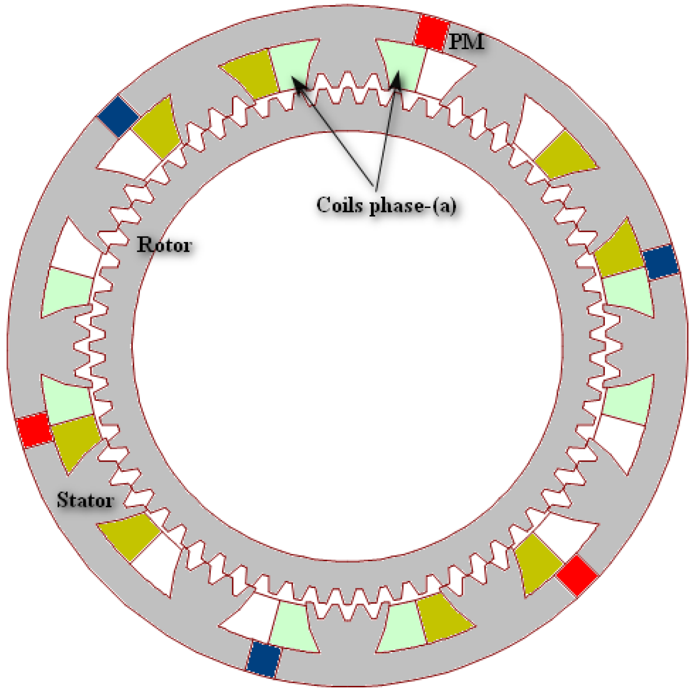
The proposed 3-phase LS–DSPM case study is presented in
Figure 2. The designed machine operates at 50 rpm and is able to deliver about 10 kW. This corresponds to a rated torque of 2000 N.m. The studied machine has 48 small stator teeth (N
s) and 64 small rotor teeth (N
r) (this is why it is called a 48/64 structure). The main dimensions and material characteristics are the same as those of the machine studied in [
1] and are given in
Table 1. To improve the performance of the machine studied in [
1], whose stator contains four pieces of PMs for magnetic field excitation, the stator of the new proposed structure contained six PMs magnetized in a tangential direction. The armature winding adopted was a 3-phase double-layer winding structure, shown in
Figure 1. The armature coils were wound around 12 salient stator-tooth poles (N
p = 12).
An uniform current density of is considered into each supplied half slot (corresponding to a supplied phase), where represents the coil fill factor and A/mm2 the current density in the winding conductors.
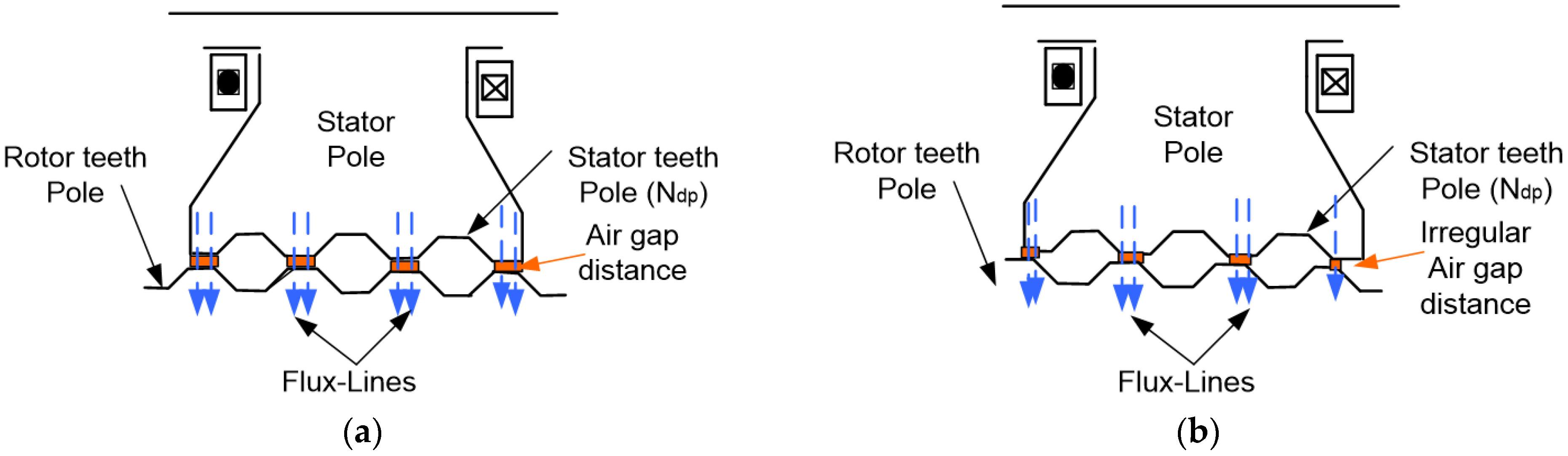
Each stator pole had four small teeth (N
dp = 4). In this structure, to create an irregular air gap between the stator and the rotor pole (
Figure 2), the stator tooth pitch
) is taken to be different from the rotor one
). Both pole pitches are given in Equation (1).
In order to operate the proposed machine at the same speed as the structure studied in [
1], the stator tooth pitch was varied as given in (2). This action also reduces the air gap surface between the stator/rotor poles when they are in the aligned position (
Figure 3b). This position corresponds to the complete overlap between the rotor/stator poles. The flux density reaches its maximum in this position. In contrast to the case when the tooth pitches stator/rotor are equal (
Figure 3a), the flux linkage surface (air gap distance δ) in the small teeth of the stator/rotor pole was not equal (
Figure 3b).
Nseq represents the corresponding number of stator teeth.
Taking into account only the reluctance effect, which is due to the structure core saliency, the reluctance torque produced by each phase can be expressed as:
where:
δ: air gap distance;
L: core axial length;
Rr: rotor outer radius;
μ0: air magnetic permeability, and Bg is the density of the air gap flux.
3. Design Optimization
The particle swarm optimization (PSO) method was applied to design the proposed machine. For comparison reasons, the external volume was kept the same as that studied in [
1], whose dimensions are given in
Table 1.
The design of the machine was realized as follows.
In the first step, the optimization method was applied to minimize torque density (10).
where: M is the sum of the masses of copper, iron, and PMs.
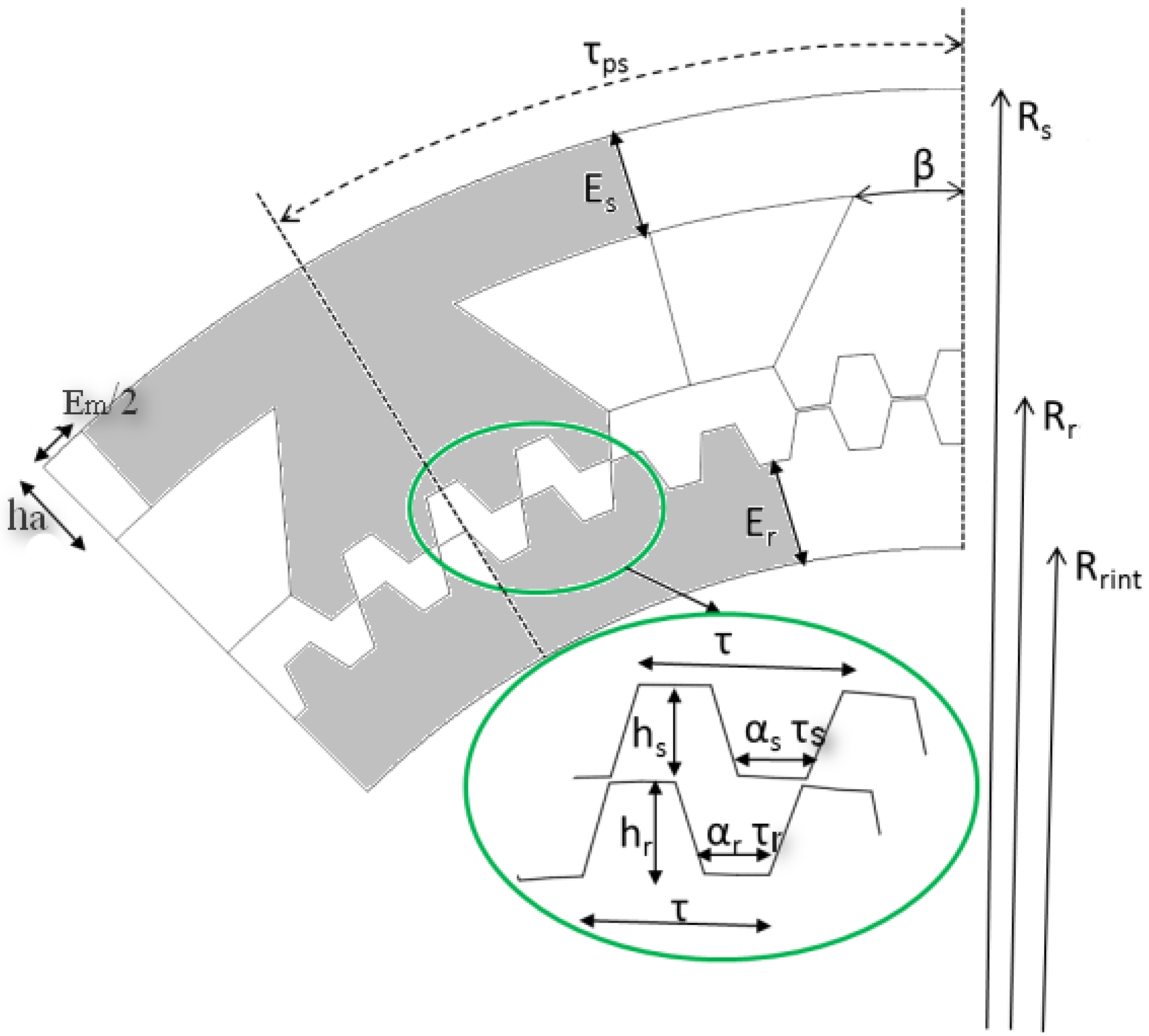
The optimization variables are all the geometric parameters shown in
Figure 4 and given in
Table 2. The small teeth constituting the poles of the stator and the rotor had little impact on the total mass of the machine; this is why in this first phase of the design, the parameters of the pole teeth were kept equal to those of the reference machine (
Table 2).
The geometric parameters of the structure studied in the [
1] were retained for the initial design of the proposed machine (at the beginning of optimization process).
In a second step, once the optimal machine was obtained in the first design, the PSO algorithm was applied to minimize electromagnetic torque ripple by taking into account only the small teeth parameters (
Table 3) as optimization variables. These small teeth had a direct impact on the shape and the value of the torque produced, because the passage of the stator field created by the PMs and the phase currents was taking place around them. This is why the determination of the parameters of small teeth was dissociated from that of the overall design (optimal parameters values obtained in the first step of design optimization). For this second step of optimization, the parameters given in
Table 2 were fixed to the values determined in the first design.
Moreover, in order to keep a mean torque close to the nominal torque required by the specifications, the optimization was performed for a mean torque equal to or superior to the value 2000 Nm. This point was introduced as a constraint of feasibility in the optimization process.
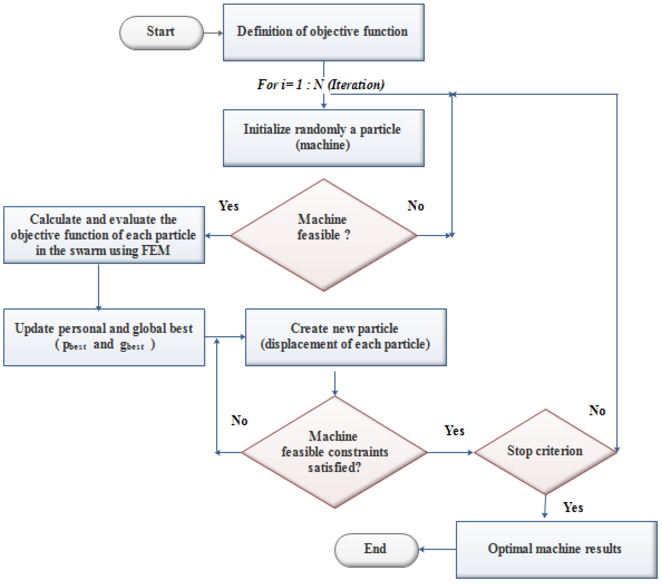
The design process optimization via the PSO method is given in
Figure 5. The optimization problem was written in the form of a Lua script program that was associated with FEMM software for the finite element electromagnetic analysis.
Particle swarm optimization was initialized with a population of machines. These particles are randomly positioned in the search space of the problem. For each particle, the values of the objective function is calculated and stored. These values correspond to the . The best () value of the objective function obtained is also terminated and stocked. Thereafter, for each iteration, the objective function of each machine is updated (by updating its “velocity” and “position”), after having compared it with that of its neighborhood value, and with the global best value. This action leads to the displacement of the particle in the search space.
Velocity (acceleration) is weighted by a random term, with separate random numbers being generated for acceleration toward
and
. The particle updates its “velocity” and “position” with the following equations [
10,
20]:
where
,
,
and
are current position, velocity, fitness value, and best value tracked, respectively.
is the coefficient of constriction:
where
is the confidence coefficient.
and
are the acceleration coefficients which are calculated as follows:
In the design optimization process of the proposed structure, an evaluation of the geometry to determine the geometric feasibility (feasibility test) was performed within the optimization algorithm for each candidate (set of parameters) element. This test allows for avoiding the study of geometrically impossible solutions. If the machine (i) with the dimensions xi is feasible, the calculation of output performance data is performed using the finite element method. Otherwise, all the parameters are initialized at random again until geometric feasibility is achieved.
4. Optimization Results and Discussion
The global optimization, which corresponds to the maximization of the torque density F1(x) (torque-to-mass ratio), was carried out in 50 iterations. The search for the global optimum took about 13 h. The characteristics of the used computer were: processor: Intel(R) Core(TM) 2.30 GHz, 16 GB RAM.
On the other hand, the search for minimum torque ripple, F2(x), which corresponds to the optimization of the small teeth parameters, was carried out with 30 iterations that represented around 4 h of calculation.
The PSO tuning parameters used were [10, 20]: φ = 4.1; χ = 0.7298; C
1, C
2 ∈ [0, 2.05]. The PSO parameters were chosen in accordance with [
20].
4.1. Torque and Torque Ripple Evaluations
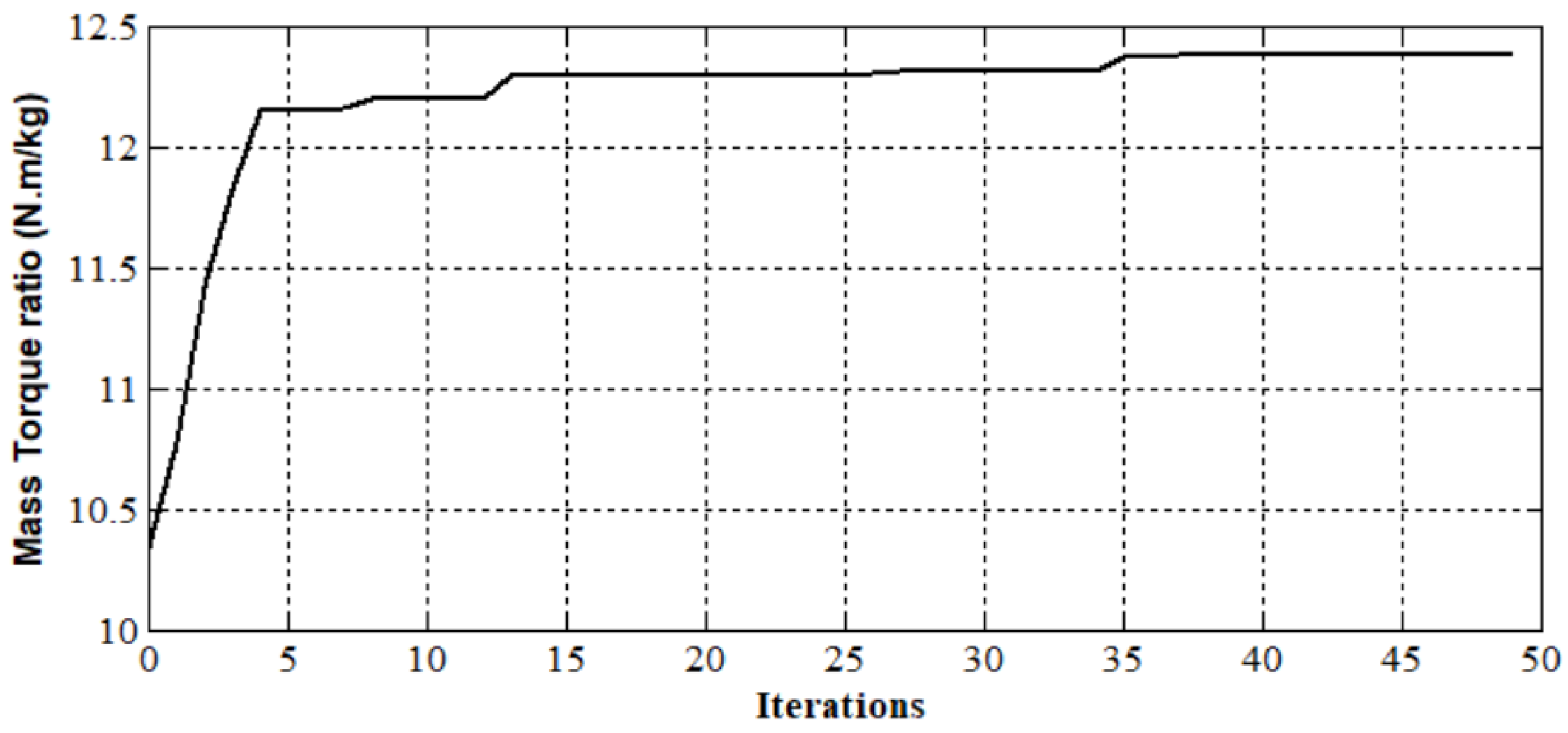
The evolution of the first objective function relative to the global parameters of the machine as a function of the number of iterations is presented in
Figure 6, and the corresponding optimal parameters are illustrated in
Table 4. The maximum torque density (the optimal machine) was approximatively obtained at iteration 35; beyond that, the objective function remained practically constant. The optimum torque density was 12.4 Nm/kg.
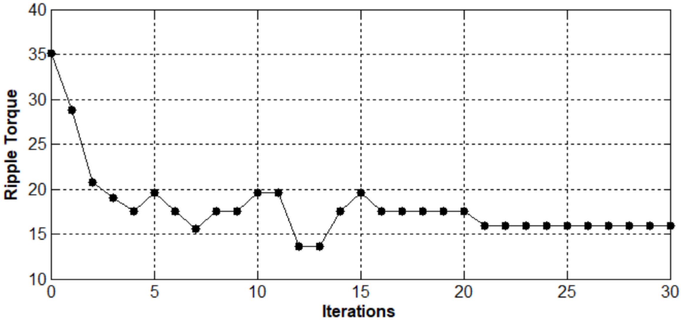
The evolution of the second objective function relative to the small teeth parameters, which corresponds to the ripple torque minimization versus the number of iterations, is presented in
Figure 7. In addition, the optimal small teeth parameters obtained after step 2 are given in
Table 5. The minimum ripple torque was obtained at iteration 21; beyond that, the objective function remained practically constant. The optimum ripple torque was reached and equal to 16%. With the optimization design approach, the ripple torque was reduced about 53% in comparison with the structure studied in [
1].
Nevertheless, the torque ripple remains important. So in order to reduce the torque ripple to acceptable values, an indirect control technique was applied in
Section 5.
4.2. Electromagnetic Characteristics
Two-dimensional FEM (FEMM software) was used to analyze the magnetic characteristic of the proposed structure in order to establish an electromechanical model of the structure.
4.2.1. Magnetic Flux Density Distribution and Flux Lines
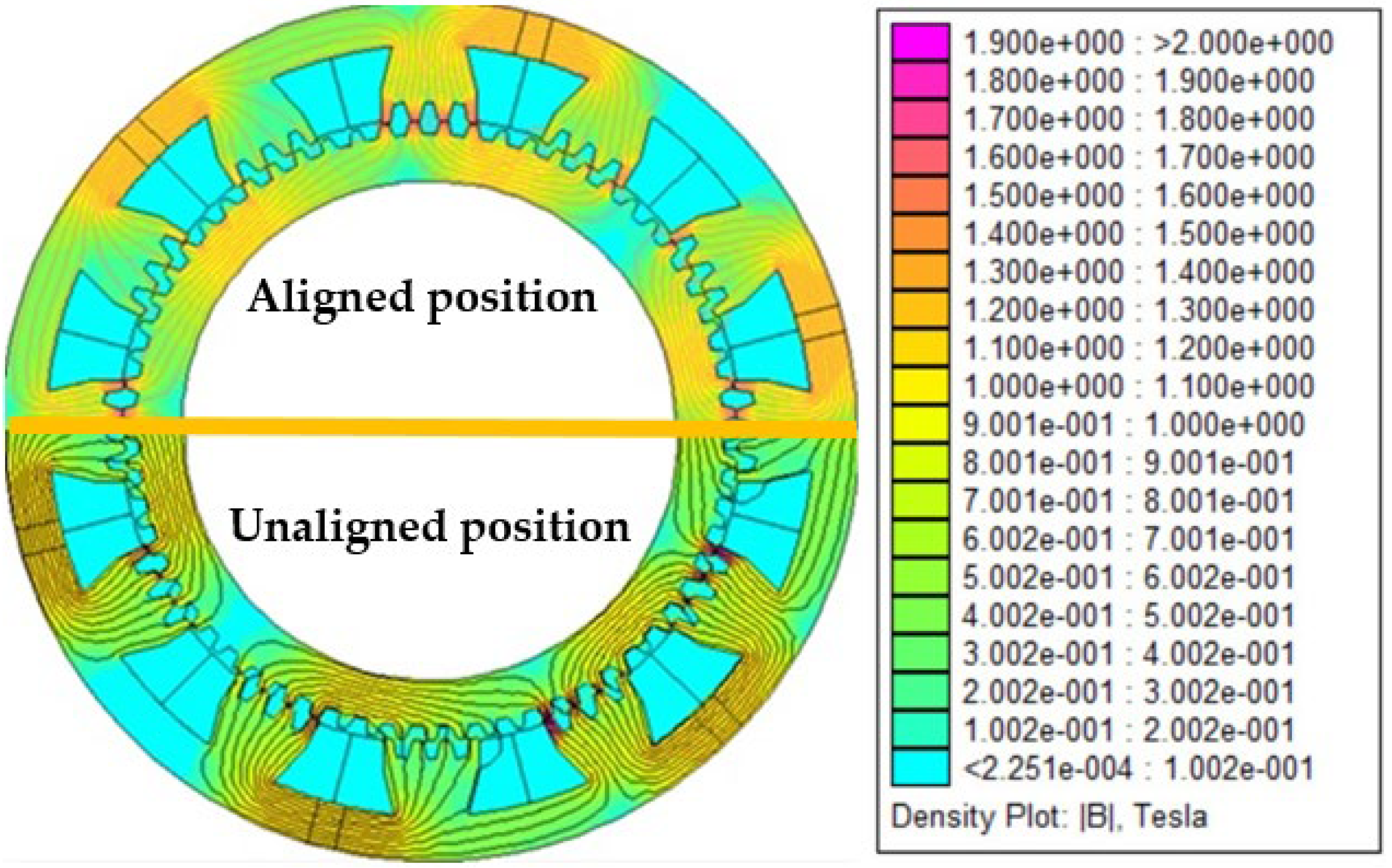
The magnetic flux density distribution at no load in different machine regions is presented in
Figure 8. It is shown that the highest magnetic flux density was focused on the poles and on the small teeth specifically at the aligned position (conjunction position). Nevertheless, recorded values did not exceed 1.45T.
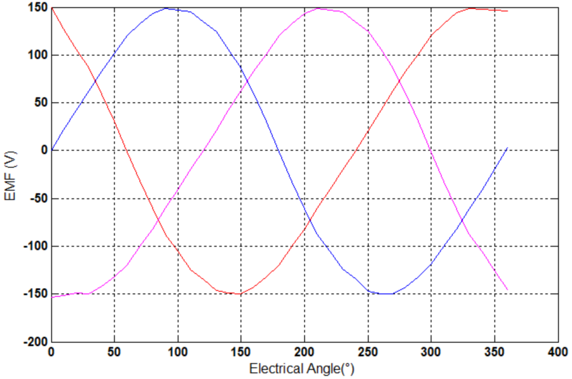
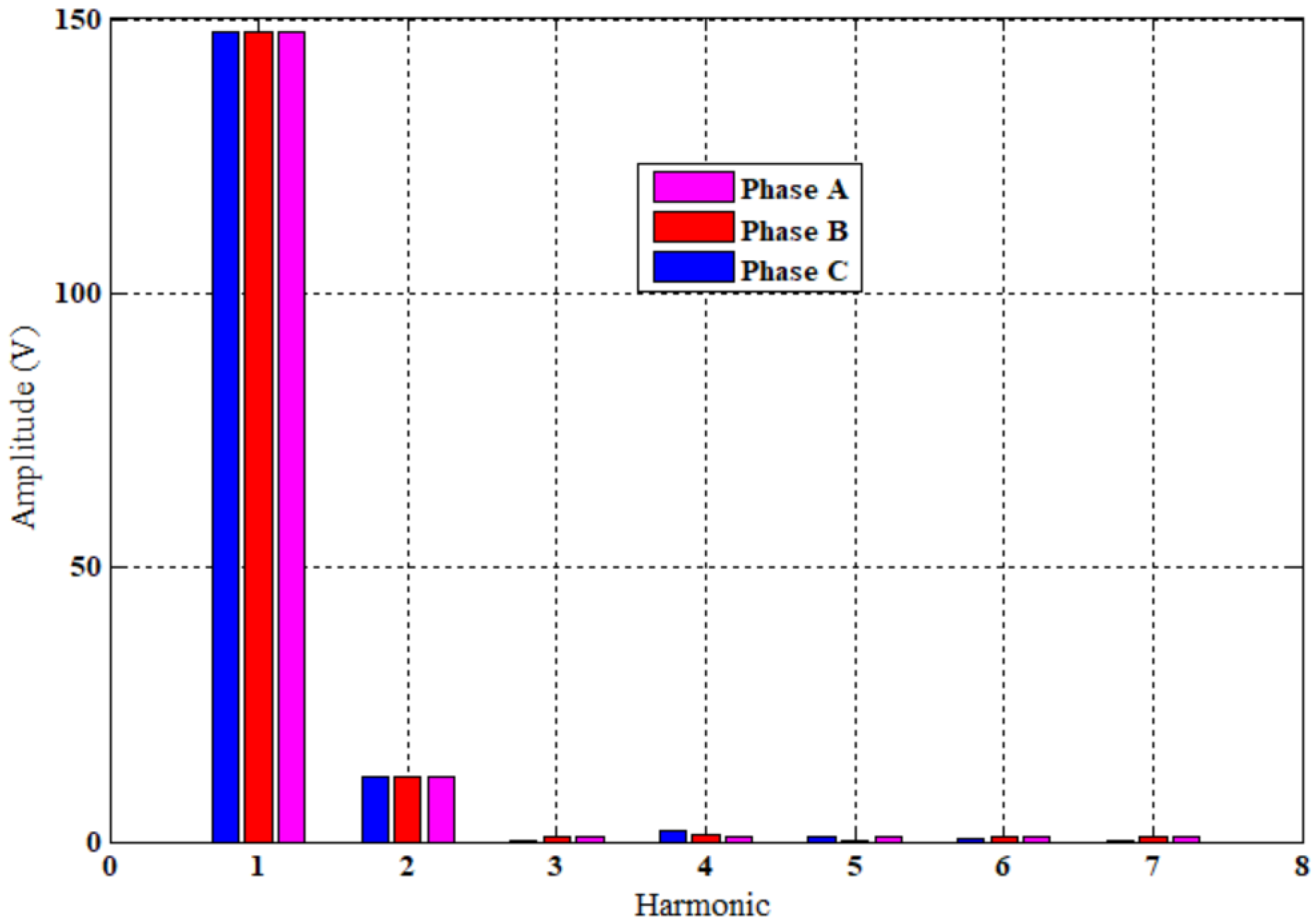
4.2.2. Three-Phase EMF under 50 rpm
The electromotive force (EMF) generated by the studied machine at 50 rpm (
Figure 9) had a sinusoidal shape and a very low harmonic content, THD = 8.8% (
Figure 10). This characteristic was obtained by the fact of the non-equality between the value of the stator/rotor tooth pitches and therefore the irregularity of the air gap in the poles of the stator/rotor, which were face-to-face. It can be observed also that the EMF amplitudes of the three phases were equal. Compared to the EMF generated by the reference machine studied in [
1], the location of permanent magnets allowed for the elimination of the asymmetry of the amplitude of EMF of the three phases.
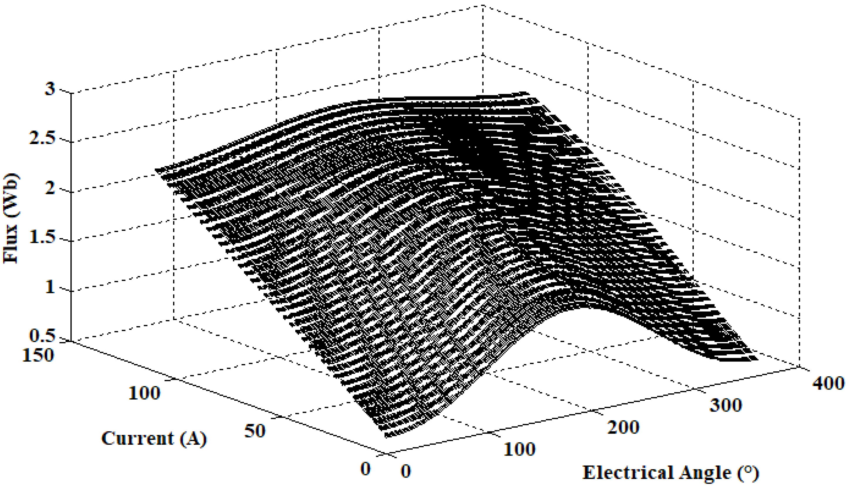
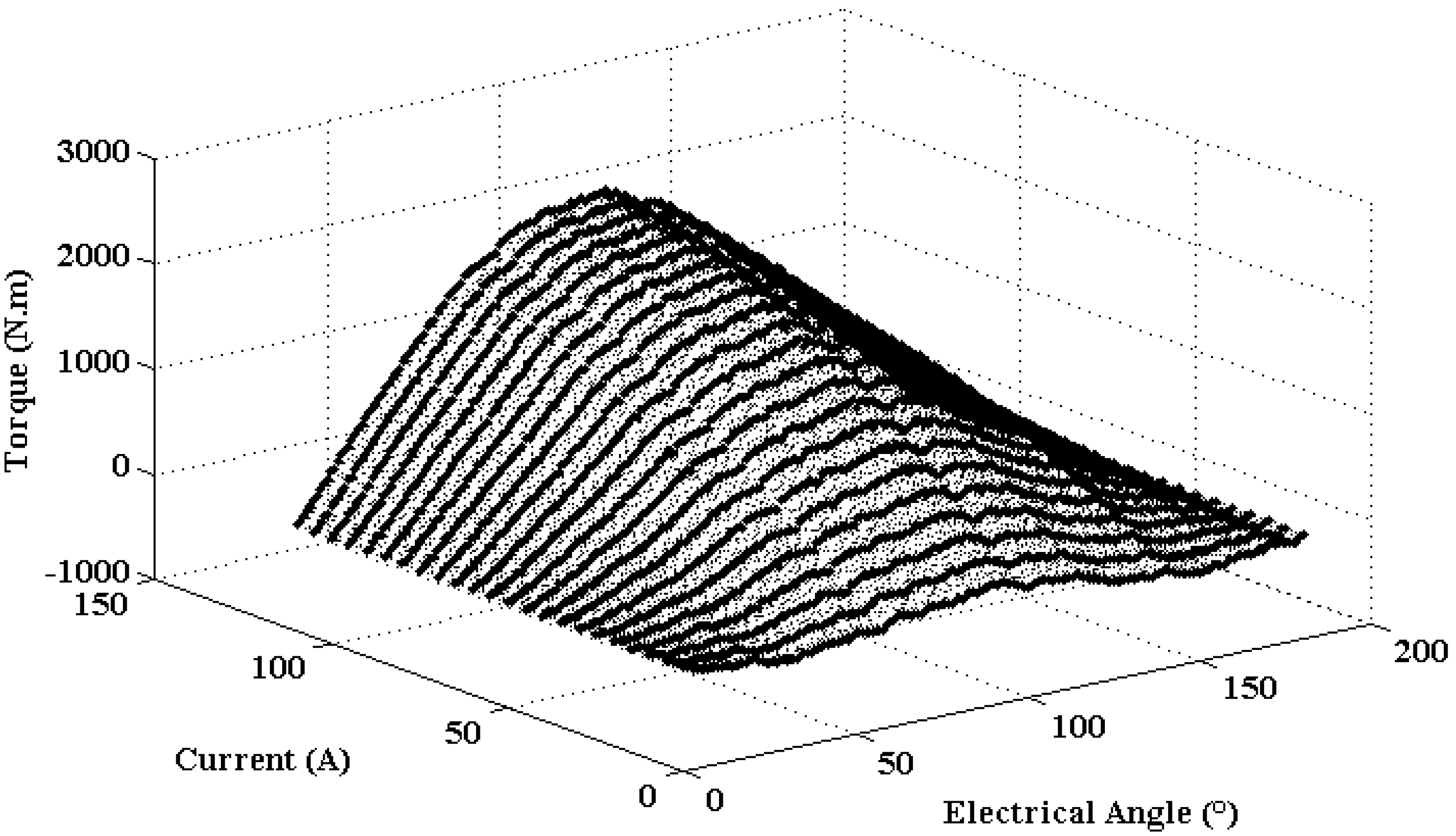
4.2.3. Flux and Torque Curve Network Characteristics
The flux and torque curve of the studied machine are presented in
Figure 11 and
Figure 12, respectively. These characteristics were obtained by using 2D-FEM, by varying the phase current from 0 A to 120 A with steps of 1 A, and electrical angle from 0° to 360° with step 1°.
The flux curves (
Figure 11) obtained were between those corresponding to θ = 0° (unaligned position) and θ = 180° (aligned position). These characteristics were linear for values of electrical angle θ close to 0°, and strongly nonlinear for values close to the aligned position. In
Figure 12, it is also notable that the difference between the curves of the torque decreased as the current increased.
The flux linkage and the torque characteristics had nonlinear properties that strongly depended on the phase current values and the rotor position. These data of the torque and the flux were used in
Section 5 to minimize the ripple torque by using TSF control.
5. Torque Ripple Minimization
An indirect control method named the torque sharing function (TSF) technique [
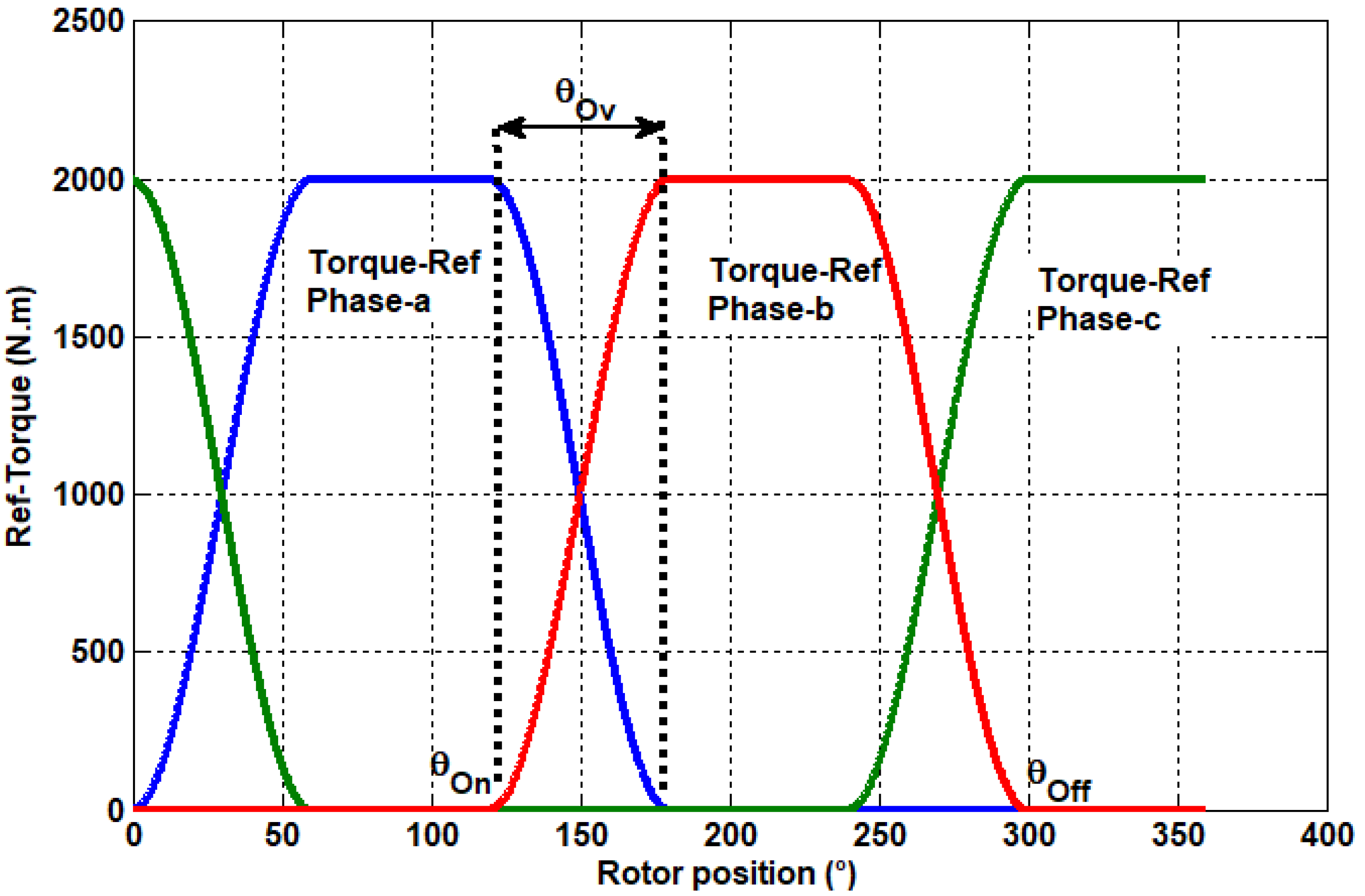
11] was applied in order to minimize the torque ripple produced by the proposed machine. In this method, the imposed reference torque forces the output torque to follow up on it. The form of reference torque
used in this work is presented in
Figure 13 and given by:
where
, , are the turn-on, overlap, and turn-off angles, respectively. is the desired torque value. In the studied case 2000 Nm.
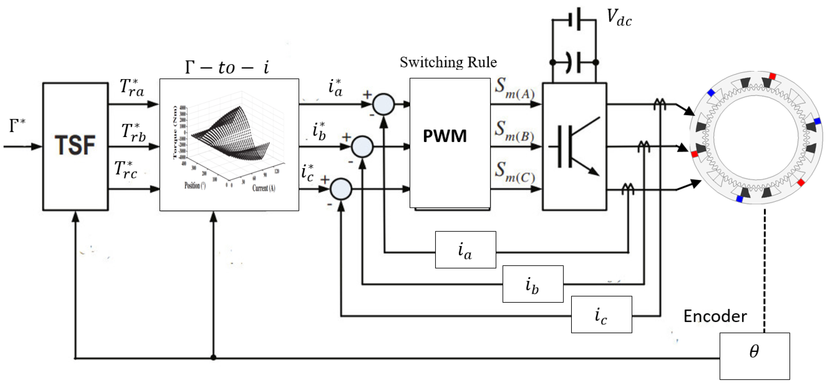
The data of nonlinear characteristics given in
Figure 11 and
Figure 12 were interpolated by the Kriging method [
21,
22], given in Equation (17), in order to generate reference currents (
,
and
). The letters were compared to the measured currents to control the active switching signal of an asymmetric converter. The global simulation of the whole system (machine, converter, and control) was executed in the MATLAB/Simulink environment based on the block diagram given in
Figure 14.
5.1. Results and Discussion
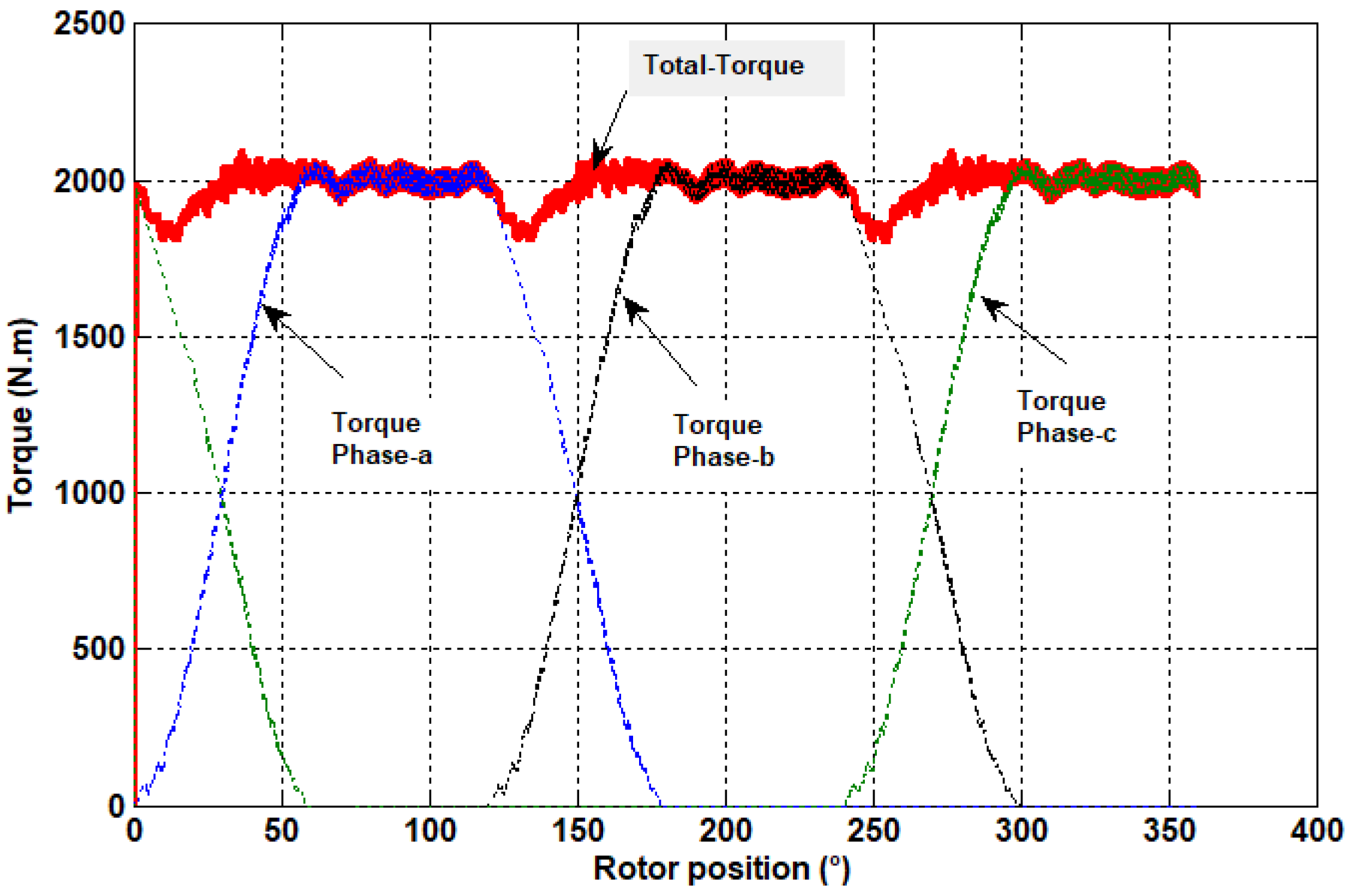
The torque waveform produced by the three phases, as well as the total torque as a function of the position, are shown in
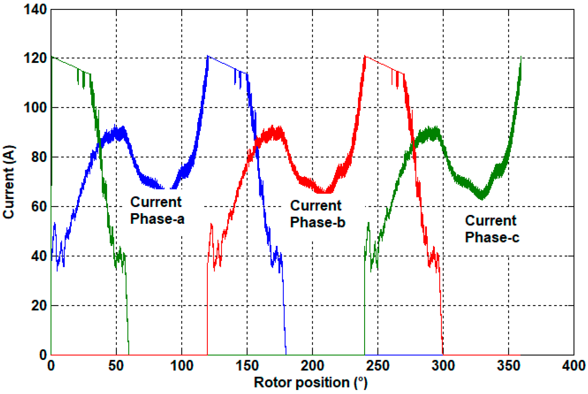
Figure 15. The current shape of each phase is presented in
Figure 16. It is illustrated that, by applying the TSF control technique, the total torque obtained was practically constant. The torque ripple recorded was around 8%, with a torque maximal value of 2086.2 Nm, a minimal torque value of 1926.2 Nm, and an average torque of 2000 Nm. The ripple was drastically reduced by approximately 50% compared to that obtained with classical supply (
Section 4) and by about 76% compared to the structure studied in [
1]. These results allow us to conclude that the application of the TSF method to the control of the proposed machine produces a very smooth torque, which leads to a quiet operation of the machine and vibration reduction.
5.2. Impact of the Overall Angle in the Torque Ripple
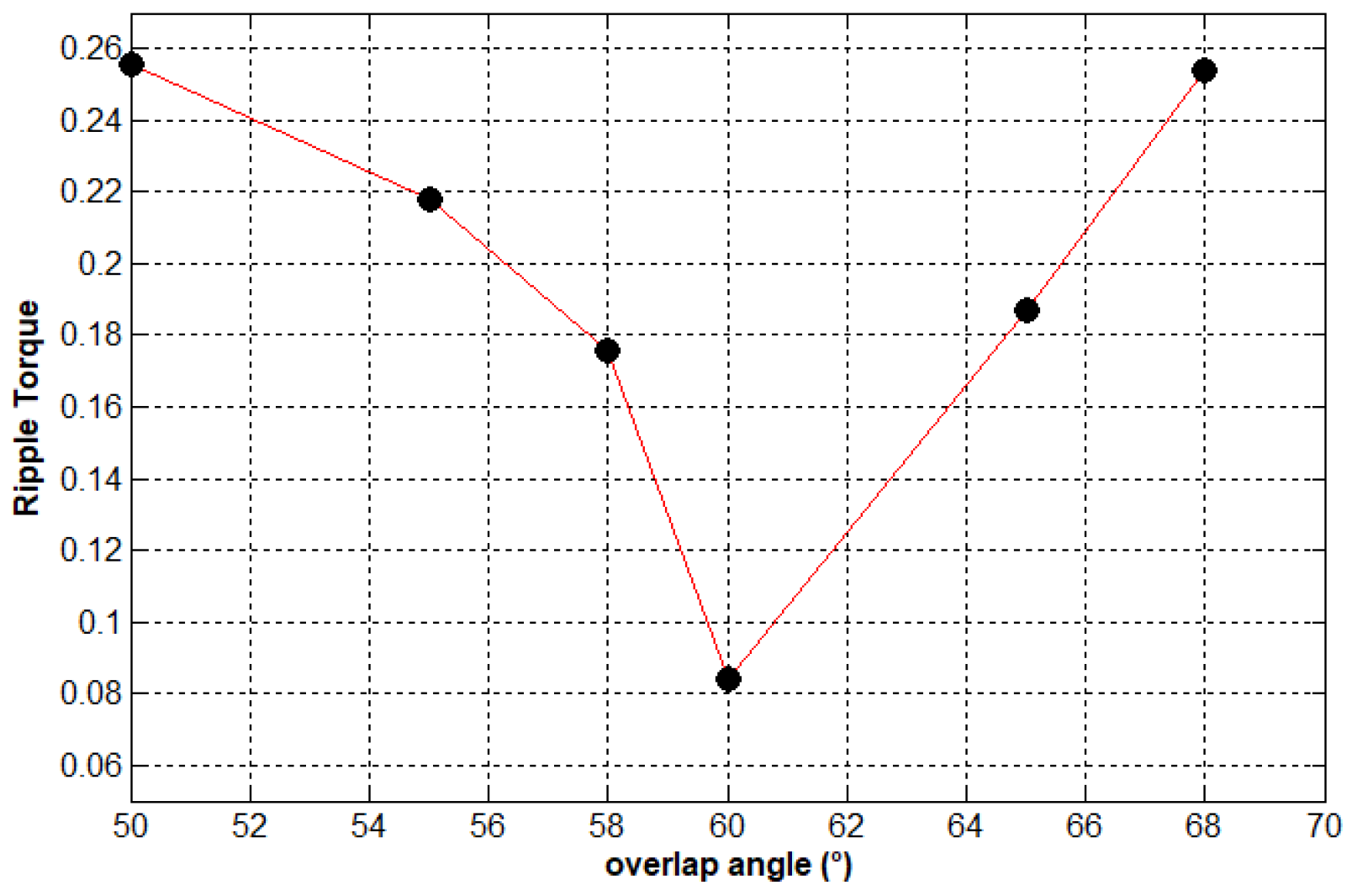
In the commutation zone, when switching off phase a (for example) and powering phase b, the current in phase a decreased at the same time as the current in phase b increased. Due to the inductive property of the machine winding, the downward and upward currents occurred with delay (
Figure 16). This phenomenon had a direct impact on the waveform of the total torque because the total torque generated dipped in these commutation zones. An adequate overlap angle leads to reduce the drop in this part of the machine’s torque, and therefore the torque ripple. As shown in
Figure 17, the optimum value of the overlap angle for which the torque ripple was minimal is 60°.
6. Efficiency
To evaluate the efficiency of the studied machine, the joule and iron losses were taken into account.
6.1. Joule Losses Estimation
The joule losses were estimated by:
From the shape of the current (
Figure 16), between [0°, 180°] it can be seen that, in phase a, for example, the current amplitude varied according to the position of the rotor. In the interval [0°–50°], the current amplitude was around 90 A, while in [50°–100°], the current amplitude was approximately 65 A, and between 100° and 180°, the current amplitude was around 120 A. This indicates that the average amplitude of the current supplying the machine’s phases was around 75 A, which transforms Equation (18) into (19).
where R
th and I
m are the resistance and current amplitude of the phase k (k = a, b and c). The phase resistance R
th is calculated by taking in account the conductors in the slots and in the end-windings [
7].
6.2. Iron Losses Estimation
The mean iron losses in the proposed structure were evaluated using the classical Bertotti formula [
23,
24] and the knowledge of the information supplied by the used M400-50 A electrical lamination manufacturer data sheet.
The first term in (20) is the hysteresis losses, the second is the excess losses and the third term is the classical eddy current losses. Bm is the mean value of the magnetic flux density.
In the studied machine, the rotor movement led to a variation of reluctance; therefore, a variation of flux density in the iron parts due to alignment and misalignment of stator/rotor pole teeth. Therefore, the iron losses were determined (using Equation (20)) according to the flux density variation in the different parts of the machine at one operating cycle.
The definition of the different coefficients used in Equation (20), and the values of joule and iron losses are summarized in
Table 6.
According to the results of iron losses estimation (
Table 6), it is shown that the totality of iron losses were localized in the stator (61.4%), and the global iron losses represented 2.27% of the output power. As for the joule losses, they represented 6% of the rated power, which means the efficiency of the proposed machine was around 92%. The efficiency of the machine could be improved by minimizing the joule losses. The latter can be minimized by changing the current in the control approach, as demonstrated in [
25].
The efficiency of the proposed structure is practically the same as that of the conventional permanent magnet synchronous machine (PMSM) studied in [
26]. The machines studied in [
26] was designed for naval propulsion, and operated at 600 rpm and delivered 10 kW.
The active weight of the studied machine (including mass of iron, mass of copper and masse of PM) was 241.17 kg and that of the PMSM studied in [
26] was about 41.40 (kg). Therefore, the weight of the proposed machine is approximatively 6 times greater than the weight of the PMSM machine studied in [
26]. However, it should be noted that the machine studied in [
26] operated at higher speed (600 rpm) than the studied DSPM machine and so the torque of this PMSM was 12 times lower than that of the studied DSPM. That means that studied DSPM has a higher torque-to-mass ratio.
7. Conclusions
In this paper, we present a contribution to the improvement of the performance of a LS–DSPM excited by PMs housed in the stator. The objective was to both improve the torque density and reduce the electromagnetic torque ripples generated by the machine. The solution proposed consists in firstly optimizing the electromagnetic design of the new structure and second, in the application of a torque-sharing function strategy for the machine’s control. An optimization algorithm based on PSO was applied first, for the optimization of the machine’s global parameters in order to maximize the torque density. In the second step, an optimization method was applied for the research of the optimum stator and rotor tooth pitch parameters to minimize torque ripple. Static and dynamic performances were obtained using 2D-FEM and MATLAB/Simulink software. At the end of this optimal design step, the proposed structure geometry with classical supply strategy produced a torque with a ripple of around 16%, but this was about 53% less than that produced by the previously studied structures. To improve this ripple, a torque-sharing function technique was applied for the control of phase supply currents. This technique allows for reducing ripple torque by approximately 76%. The optimization study presented in this paper shows that the proposed LS-DSPM can match the performance of a 10 kW 50 rpm wind turbine generator with the following advantages in comparison with other previously studied machines: lower magnet mass and cost, relatively small torque ripples, and simple winding manufacturing.
Author Contributions
Conceptualization, T.K., C.G. and J.-F.C.; methodology, C.G. and J.-F.C.; software, validation, T.K., C.G. and J.-F.C.; formal analysis, investigation, resources, data curation, T.K., C.G. and J.-F.C.; writing—original draft preparation, T.K., C.G. and J.-F.C.; writing—review and editing, T.K., C.G., J.-F.C., N.B., L.H. and L.B.; visualization, T.K., C.G. and J.-F.C.; supervision, C.G., J.-F.C. and N.B. All authors have read and agreed to the published version of the manuscript.
Funding
This research received no external funding.
Data Availability Statement
Not applicable.
Conflicts of Interest
The authors declare no conflict of interest.
References
- Saou, R. Modélisation et Optimisation de Machines Lentes à Aimants Permanents: Machines à Double Saillance et à Inversion de Flux. Ph.D. Thesis, Université de Bejaia, Bejaia, Algeria, 2008. [Google Scholar]
- Zaim, M.E.; Moreau, L.; Alli, S.S.; Bracikowski, N. Structures of low speed doubly salient permanent magnet machine. In Proceedings of the 2017 IEEE Vehicle Power and Propulsion Conference (VPPC), Belfort, France, 11–14 December 2017; pp. 1–6. [Google Scholar]
- Guerroudj, C.; Saou, R.; Boulayoune, A.; El-hadi Zam, M.; Moreau, L. Performance Analysis of Vernier Slotted Doubly Salient Permanent Magnet Generator for Wind Power. Int. J. Hydrogen Energy 2017, 42, 87448755. [Google Scholar] [CrossRef]
- Bekhouche, L.; Saou, R.; Guerroudj, C.; Kouzou, A.; Zam, M.E.H. Electromagnetic Torque Ripple Minimization of Slotted Doubly Salient Permanent-Magnet Generator for Wind Turbine Applications. Prog. Electromagn. Res. M 2019, 83, 181190. [Google Scholar] [CrossRef]
- Guerroudj, C.; Charpentier, J.-F.; Saou, R.; Karnavas, Y.L.; Bracikowski, N.; Zaïm, M.E.-H. Coil Number Impact on Performance of 4-Phase Low Speed Toothed Doubly Salient Permanent Magnet Motors. Machines 2021, 9, 137. [Google Scholar] [CrossRef]
- Liu, C. Emerging electric machines and drives—An overview. IEEE Trans. Energy Convers. 2018, 33, 2270–2280. [Google Scholar]
- Niu, S.; Wang, S.; Zhao, X. Overview of stator slot-opening permanent magnet machines. IEEE Trans. Transp. Electrif. 2022, 9, 782–804. [Google Scholar]
- Du, Y.; Mao, Y.; Xiao, F.; Zhu, X.; Sun, Y.; Quan, L. A pole-changing doubly salient permanent magnet motor. IEEE Trans. Transp. Electrif. 2022, 8, 2479–2489. [Google Scholar] [CrossRef]
- Rezzoug, A.; Zam, M.E.H. Non-Conventional Electrical Machines; John Wiley and Sons Inc.: Hoboken, NJ, USA, 2011. [Google Scholar]
- Boulayoune, A.; Guerroudj, C.; Saou, R.; Moreau, L.; Zaim, M.E.H. Optimisation par essaim de particule et algorithme génétique d’une machine à inversion de flux. Rev. Roum. Sci. Techn. Électrotechn. et Énerg. 2017, 62, 19–24. [Google Scholar]
- Suriano-Sánchez, S.I.; Ponce-Silva, M.; Olivares-Peregrino, V.H.; De León-Aldaco, S.E. A Review of Torque Ripple Reduction Design Methods for Radial Flux PM Motors. Eng 2022, 3, 646–661. [Google Scholar] [CrossRef]
- Sahoo, S.K.; Panda, S.K.; Xu, J. Iterative learning-based high performance current controller for switched reluctance motors. IEEE Trans. Energy Convers. 2004, 19, 491–498. [Google Scholar] [CrossRef]
- Mikail, R.; Husain, I.; Sozer, Y.; Islam, M.; Sebastain, T. Torque ripple minimization of switched reluctance machines through current profiling. IEEE Trans. Ind. Appl. 2013, 49, 1258–1267. [Google Scholar] [CrossRef]
- Shaked, N.T.; Rabinovici, R. New procedures for minimizing the torque ripple in switched reluctance motors by optimizing the phase-current profile. IEEE Trans. Magn. 2005, 41, 1184–1192. [Google Scholar] [CrossRef]
- Xue, X.D.; Cheng, K.W.E.; Ho, S.L. Optimization and evaluation of torque sharing function for torque ripple minimization in switched reluctance motor drives. IEEE Trans. Power Electron. 2009, 24, 2076–2090. [Google Scholar] [CrossRef]
- Pop, A.C.; Petrus, V.; Martis, C.S.; Iancu, V.; Gyselinck, J. Comparative study of different torque sharing functions for losses minization in switched reluctance motors used in electric vehicles propulsion. In Proceedings of the 13th International Conference on Optimization of Electrical and Electronic Equipment (OPTIM), Brasov, Romania, 24–26 May 2012; IEEE: Piscataway, NJ, USA, 2012; pp. 356–365. [Google Scholar]
- Ye, J.; Bilgin, B.; Emadi, A. An offline torque sharing function for torque ripple reduction in switched reluctance motor drives. IEEE Trans. Energy Convers. 2015, 30, 726–735. [Google Scholar] [CrossRef]
- Ye, J.; Bilgin, B.; Emadi, A. An extended-speed low-ripple torque control of switched reluctance motor drives. IEEE Trans. Power Electron. 2015, 30, 1457–1470. [Google Scholar] [CrossRef]
- Lee, D.H.; Lee, Z.G.; Ahn, J.W. A simple nonlinear logical torque sharing function for low-torque ripple SRdrive. IEEE Trans. Ind. Electron. 2009, 56, 3021–3028. [Google Scholar] [CrossRef]
- Clerc, M.; Kennedy, J. The particle swarm-explosion, stability, and convergence in a multidimensional complex space. IEEE Trans. Evol. Comput. 2002, 6, 58–73. [Google Scholar] [CrossRef]
- Moreau, L.; El Hadi Zaïm, M.; Machmoum, M. Control Optimization of a Slotted Switched Reluctance Generator for High-torque Applications. Electr. Power Compon. Syst. 2014, 42, 629–638. [Google Scholar] [CrossRef]
- Moreau, L. Modélisation, Conception et Commande de Génératrices à Réluctance Variable Basse Vitesse. Ph.D. Thesis, Université de Nantes, Nantes, France, 2005. [Google Scholar]
- Bertotti, G. Physical interpretation of eddy current losses in ferromagnetic materials. I. Theoretical considerations. J. Appl. Phys. 1985, 57, 2110–2117. [Google Scholar] [CrossRef]
- Krings, A.; Soulard, J. Overview and Comparison of Iron Loss Models for Electrical Machines. J. Electr. Eng. 2010, 10, 162–169. [Google Scholar]
- Ye, W.; Ma, Q.; Zhang, P. Improvement of the torque-speed performance and drive efficiency in an SRM using an optimal torque sharing function. Appl. Sci. 2018, 8, 720. [Google Scholar]
- Park, J.-H.; Lee, T.-W.; Jeong, Y.-H.; Hong, D.-K. Novel Multi-Physics Computational Simulation of a 10 kW Permanent Magnet Motor for Podded Propulsion. Energies 2022, 15, 6607. [Google Scholar] [CrossRef]
Figure 1.
Reference LS–DSPM machine [
1].
Figure 1.
Reference LS–DSPM machine [
1].
Figure 2.
Proposed LS–DSPM machine.
Figure 2.
Proposed LS–DSPM machine.
Figure 3.
Stator/rotor tooth pole pitch. (a) Regular air gap distance. (b) Irregular air gap distance.
Figure 3.
Stator/rotor tooth pole pitch. (a) Regular air gap distance. (b) Irregular air gap distance.
Figure 4.
Global parameters of the proposed machine.
Figure 4.
Global parameters of the proposed machine.
Figure 5.
Design optimization process flowchart.
Figure 5.
Design optimization process flowchart.
Figure 6.
Torque density versus iterations (F1(x)).
Figure 6.
Torque density versus iterations (F1(x)).
Figure 7.
Torque ripple versus iterations (F2(x)).
Figure 7.
Torque ripple versus iterations (F2(x)).
Figure 8.
Magnetic field distribution and flux lines at no load.
Figure 8.
Magnetic field distribution and flux lines at no load.
Figure 9.
Three-phase EMF.
Figure 9.
Three-phase EMF.
Figure 11.
Magnetic flux versus electrical angle for different and phase currents ψ = f(i, θ).
Figure 11.
Magnetic flux versus electrical angle for different and phase currents ψ = f(i, θ).
Figure 12.
Torque versus electrical angle and phase currents. Γ = f(i, θ).
Figure 12.
Torque versus electrical angle and phase currents. Γ = f(i, θ).
Figure 13.
Cubic form of the reference torque for each phase.
Figure 13.
Cubic form of the reference torque for each phase.
Figure 14.
Ripple torque control block diagram.
Figure 14.
Ripple torque control block diagram.
Figure 15.
Overall torque waveform (at 50 rpm).
Figure 15.
Overall torque waveform (at 50 rpm).
Figure 16.
Current waveform (at 50 rpm).
Figure 16.
Current waveform (at 50 rpm).
Figure 17.
Ripple torque versus overlap angle.
Figure 17.
Ripple torque versus overlap angle.
Table 1.
Dimensions and material of the reference LS–DSPM machine [
1].
Table 1.
Dimensions and material of the reference LS–DSPM machine [
1].
| Parameters | Values |
|---|
| Stator outer diameter, Do | 600 mm |
| Active axial length, L | 200 mm |
| Air gap, g | 0.5 mm |
| Copper fill factor, kr | 0.5 |
| Current density, J | 5 A/mm2 |
| Number of turns per phase, N | 160 |
| Sheet thickness (M400-50 A) | 0.5 mm |
| PMs type, NdFeBr | Br = 1.29 T, µr = 1.049 |
| Rated speed n, | 50 rpm |
| Rated power Pout | 10 kW |
| Torque density | 12.60 Nm/kg |
| Stator yoke thickness, Es | 31.4 mm |
| Stator teeth depth, hs | 12.8 mm |
| Rotor teeth depth, hr | 9.3 mm |
| Magnet thickness, Em | 19.5 mm |
| Stator teeth cyclic ratios, αs1 | 0.32 |
| Stator teeth cyclic ratios, αs2 | 0.33 |
| Rotor teeth cyclic ratios, αr1 | 0.30 |
| Rotor teeth cyclic ratios, αr2 | 0.44 |
| Coil height, hb | 50.7 mm |
| Inner radius of rotor, Rr | 215.3 mm |
| Angular pole opening, β | 5.5° |
| Angular slot opening, βa | 8.1° |
| Rotor yoke thickness, Er | 32.6 mm |
Table 2.
Global search variable values.
Table 2.
Global search variable values.
| Parameters (xi) | Low Values | Upper Values |
|---|
| Stator yoke thickness, Es | 20 mm | 50 mm |
| Stator teeth depth, hs | 12.8 mm | 12.8 mm |
| Rotor teeth depth, hr | 9.3 mm | 9.3 mm |
| Magnet thickness, La | 10 mm | 50 mm |
| Stator teeth cyclic ratios, αs1 | 0.32 | 0.32 |
| Stator teeth cyclic ratios, αs2 | 0.33 | 0.33 |
| Rotor teeth cyclic ratios, αr1 | 0.30 | 0. 30 |
| Rotor teeth cyclic ratios, αr2 | 0.44 | 0. 44 |
| Coil height, hb | 20 mm | 50 mm |
| Inner radius of rotor, Rr | 180 mm | 230 mm |
| Angular pole opening, β | 2° | 15° |
| Angular slot opening, βa | 2° | 15° |
| Rotor yoke thickness, Er | 20 mm | 50 mm |
Table 3.
Rotor/stator tooth pitch search variable values.
Table 3.
Rotor/stator tooth pitch search variable values.
| Variable (xi) | Low Values | Upper Values |
|---|
| hs | 2 mm | 15 mm |
| hr | 2 mm | 15 mm |
| αr1 | 0.10 | 0.5 |
| αs1 | 0.10 | 0.5 |
| αs2 | 0.10 | 0.5 |
| αr2 | 0.10 | 0.5 |
Table 4.
Optimal global variable values obtained after 1st phase of optimization.
Table 4.
Optimal global variable values obtained after 1st phase of optimization.
| Parameters (xi) | Optimal Values |
|---|
| Stator yoke thickness, Es | 30.47 mm |
| Magnet thickness, Em | 25.92 mm |
| Coil height, hb | 39.14 mm |
| Inner radius of rotor, Rr | 228.49 mm |
| Angular pole opening, β | 5.77° |
| Angular slot opening, βa | 8.34° |
| Rotor yoke thickness, Er | 26.48 mm |
Table 5.
Optimal search variable values.
Table 5.
Optimal search variable values.
| Variable (xi) | Optimal Value |
|---|
| hs | 8.4 mm |
| hr | 7.41 mm |
| αr1 | 0.30 |
| αs1 | 0.28 |
| αs2 | 0.35 |
| αr2 | 0.37 |
Table 6.
Coefficients used in (20), efficiency and losses estimation values.
Table 6.
Coefficients used in (20), efficiency and losses estimation values.
| Coefficients/Performance | Values |
|---|
| Electrical conductivity, σ | 38.105 [S/m] |
| Hysteresis losses coefficient, kh | 35.18 [Ws/m3T2] |
| Eddy currents coefficient, ke | 12.26 [Ws2/m3T2] |
| Thickness lamination d | 5.10−4 [m] |
| Joule losses | 607.50 W |
| Stator iron losses | 139.38 (W) |
| Rotor iron losses | 87.56 (W) |
| Total iron losses | 227 (W) |
| Efficiency | 92% |
| Iron density [kg/m3] | 7600 |
| Copper density [kg/m3] | 8920 |
| Active weight of machine [kg] | 7650 |
| Disclaimer/Publisher’s Note: The statements, opinions and data contained in all publications are solely those of the individual author(s) and contributor(s) and not of MDPI and/or the editor(s). MDPI and/or the editor(s) disclaim responsibility for any injury to people or property resulting from any ideas, methods, instructions or products referred to in the content. |
© 2023 by the authors. Licensee MDPI, Basel, Switzerland. This article is an open access article distributed under the terms and conditions of the Creative Commons Attribution (CC BY) license (https://creativecommons.org/licenses/by/4.0/).


 ,
, 


