Abstract
The robotic grinding system for a thin-walled workpiece is a multi-dimensional coupling system composed of a robot, a grinding spindle and the thin-walled workpiece. In the grinding process, a dynamic coupling effect is generated, while the thin-walled workpiece stimulates elastic vibration; the grinding spindle, as an electromechanical coupling actuator, is sensitive to the elastic vibration in the form of load fluctuations. It is necessary to investigate the electromechanical coupling dynamic characteristics under the vibration coupling of the thin-walled workpiece as well as the vibration control of the robotic grinding system. Firstly, considering the dynamic coupling effect between the grinding spindle and thin-walled workpiece, a dynamic model of the grinding spindle and thin-walled workpiece coupling system is established. Secondly, based on this established coupling dynamic model, the vibration characteristics of the thin-walled workpiece and the electromechanical coupling dynamic characteristics of the grinding spindle are investigated. Finally, a speed adaptive control system for the grinding spindle is designed based on a fuzzy PI controller, which can achieve a stable speed for the grinding spindle under vibration coupling and has a certain suppression effect on the elastic vibration of the thin-walled workpiece at the same time.
1. Introduction
High surface finishes are usually required for manufactured components with functional surfaces [1]. Due to the surface quality of the workpieces produced by rough processing, casting and printing are not sufficient for functional applications, so some post-processing by grinding or a similar process is usually needed to improve the surface quality and mechanical properties [2,3]. There are different surface-finishing processes for different workpiece requirements, such as burnishing, which is also known as roller burnishing, and ball burnishing, grinding, shot peening and traditional hand polishing [1,4,5], as well as some non-conventional manufacturing technologies, such as laser polishing, electrochemical machining, linear friction welding and electro-discharge machining [6,7,8,9].
For a certain period of time, many finishing processes operational in the industrial field mainly relied on traditional handmade or conventional machine tool processing; it can be seen that the existing polishing modes, whether the traditional manual mode or unconventional mode, display a working efficiency and working space that are not conducive to the flexibility necessary for machining production, especially for large-scale and complex structures. In recent years, the automation and intelligence of the manufacturing process have been an irresistible trend to adapt to the requirements of the processing environment, working space and related flexibility [10,11]. Compared with the machining equipment within these existing polishing modes, a robot conveys the advantages of higher flexibility, a larger workspace and a lower cost, which is, obviously, especially appropriate for the machining of large structures with complex shapes, such as aerospace structures, high-speed rail bodies and wind blades. In recent years, robotic grinding has attracted increasing attention from industry [11,12,13,14]. However, the lower stiffness of the robotic grinding system in the machining process, which is mainly caused by the articulated links and flexible joints, easily stimulates the coupling vibration, which has remained an essential issue affecting the stability of robotic machining, especially for the thin-walled workpiece [12,13].
To improve the machining stability and surface quality, some scholars studied the influence of the process parameters on the surface quality of polishing [5,6,7,15,16] as well as the working stiffness optimization and machining accuracy compensation through posture optimization [17,18,19,20]. Moreover, research indicated that support fixtures are essential to ensure the stability of the milling process, affecting the surface and deflection of the workpiece [21,22,23,24]. However, this is a challenge for the support fixtures of a complex workpiece, particularly regarding flexible structures, for which the local stiffness of the part is affected and may even result in an additional deformation that amplifies the cutting instability. On the other hand, it is known that the machining chatter also has an important influence on the machining surface quality, so some optimization approaches and control strategies of robotic machining chatter were also proposed [25,26,27,28]. These optimization methods mainly focus on the machining spindle unit.
As shown in Figure 1, the robotic grinding system is a multi-dimensional coupling system composed of the robot, the grinding spindle and the workpiece, and there is a complex dynamic coupling effect between the subsystems. It should be pointed out that the robotic machining process is a dynamic process, and the dynamics of the system have a decisive influence on the polishing quality and stability. Some researchers have investigated the dynamic characteristics and control strategies of the robotic machining system [29,30,31,32]; however, these studies mainly focus on the robot body separately, while the dynamic coupling effect in the system is not fully considered. In the grinding process, the force interaction between the grinding spindle and the workpiece is generated by the grinding wheel, and the thin-walled workpiece, which has a lower stiffness, stimulates the time-varying elastic vibration under the moving grinding force [33,34,35,36]. On the other hand, the grinding spindle is a typical electromechanical coupling unit, in which the electromagnetic parameters are coupled with the mechanical parameters [37]. According to the schematic diagram shown in Figure 1, the stator converts the input electric energy into a rotating magnetic field, and the interaction between the stator magnetic field and the rotating magnetic field produces a driving torque that can drive the rotor. In this case, the dynamic interaction force and elastic vibration of the thin-walled workpiece significantly affect the dynamic characteristics of the grinding spindle [26,38,39]. There is a dynamic coupling effect between the spindle and the thin-walled workpiece.
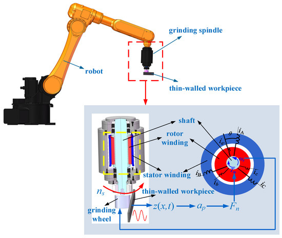
Figure 1.
Composition diagram and coupling relationship of robotic grinding system for thin-walled workpiece.
Considering the influence of the machining parameters and structural parameters, some research has been conducted on the dynamic characteristics’ analysis and the optimization design of the motorized spindle unit [40,41,42,43]. However, this research is mainly carried out for the motorized spindle separately, while the dynamic coupling effect of the workpiece is not fully considered, especially the elastic vibration of the thin-walled workpiece, which will significantly affect the grinding force. In fact, according to the electromechanical coupling principle of the robotic grinding system, the elastic vibration stimulated by the thin-walled workpiece has an important influence on the dynamic response characteristics of the grinding spindle. Reciprocally, the dynamic responses and grinding force of the grinding spindle further affect the elastic vibration of the thin-walled workpiece, which leads to a complex dynamic coupling effect between the grinding spindle and the thin-walled workpiece. It is necessary to reveal the electromechanical coupling dynamic characteristics of the grinding spindle and thin-walled workpiece coupling system, which is the basis of the vibration suppression of the robotic grinding system.
On the other hand, elastic thin-walled workpieces are typical flexible structures, and their vibration control has always been the focus of attention. There has been a lot of research on the vibration control of flexible structures, the most representative of which is the active control strategy based on intelligent materials, such as piezoelectric intelligent actuators [44,45,46], magnetorheological intelligent actuators [47,48], etc. In this case, the flexible structure becomes an intelligent structural system. However, this method is based on intelligent actuators that inevitably change the structure form, which is difficult to implement for robotic grinding processing conditions. Some studies were also conducted to suppress the chatter of the robotic machining system through machining posture optimization [49,50], auxiliary support [22,23,51], etc. Based on the dynamic coupling effect between the grinding spindle and the thin-walled workpiece, this paper attempts to realize the vibration suppression of the thin-walled workpiece through adaptive control of the grinding spindle in the machining process.
In this paper, the core goal is to reveal the electromechanical coupling dynamic characteristics of the robotic grinding system, by considering the vibration coupling effect of the thin-walled workpiece, and, according to the dynamic coupling mechanism, the speed adaptive control of the grinding spindle as well as the vibration suppression of the thin-walled workpiece are carried out. The manuscript is organized as follows. In Section 2, the dynamic model of the coupling system is established. In Section 3, the electromechanical coupling dynamic characteristics of the robotic grinding system are analyzed based on the established coupling dynamic model. In Section 4, a speed adaptive control system for the grinding spindle is designed based on a fuzzy PI controller. In Section 5, the paper is concluded with a brief summary.
2. Dynamic Model of the Coupling System
According to the coupling relationship of the robotic grinding system, as shown in Figure 1, and considering the vibration coupling effect of the thin-walled workpiece, the dynamic model of the coupling system is established, as shown in Figure 2.
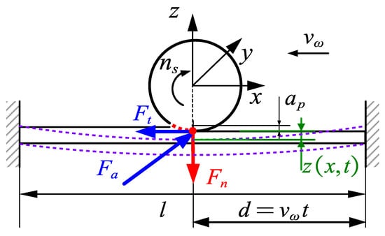
Figure 2.
Dynamic model of the coupling system.
As shown in Figure 2, the grinding force can be quadratically decomposed into grinding components in the x, y and z directions along the grinding wheel, namely, tangential grinding force Ft, axial grinding force Fa and normal grinding force Fn. Among these grinding components, the normal component Fn is the main parameter in the constant force grinding. As shown in Figure 1 and according to the coupling relationship between the grinding spindle and the thin-walled workpiece, which has been indicated in the previous analysis, the elastic vibration of the thin-walled workpiece directly causes fluctuation of the grinding depth ap as well as the grinding force, influencing the dynamic characteristics and stability of the robotic grinding system in an important way. Therefore, this paper focuses on the effect of normal component Fn and investigates the dynamic coupling relationship between the grinding spindle and the thin-walled workpiece, which can provide a theoretical basis for the subsequent control of the grinding system.
In order to analyze the coupling behavior between the grinding spindle and the thin-walled workpiece, an Euler–Bernoulli beam is used to characterize the thin-walled workpiece, and the transverse vibration z(x,t) of the thin-walled workpiece is mainly considered. To establish the vibration equation of the thin-walled workpiece, the moving grinding force can be expressed as the δ function of Fn.
where vω is the grinding feed speed, and Fn is the normal component of grinding force. In general, Fn is 1.5~3 times of Ft, which is specifically related to the abrasive particles and the workpiece materials [52,53]. Referring to the material properties, hardened steel is selected, Fn/Ft is 1/0.49 = 2.04, which can be rounded to 2; thus, it can be defined that Fn is 2 times of Ft in this paper.
In general, the grinding force is related to the workpiece material, tool material, machining parameter, machining temperature and other factors, and, of these factors, the machining parameter is the most important factor affecting machining force. Meanwhile, according to the cutting theory, there is an exponential relationship between the grinding force, which can be determined by the machining parameters and characterized with empirical formulas, and the different grinding materials and grinding conditions; the correlation coefficient is different [54,55]. To study the electromechanical coupling dynamic characteristics of the robotic grinding system, the grinding parameters and grinding conditions in this paper refer to the surface grinding conditions in the literature [53]; in this case, the grinding force can be defined as
According to the empirical formula, the grinding force is a constant mean value when the machining parameters are given. Considering the dynamic coupling effect of the thin-walled workpiece, the transverse vibration z(x,t) of the thin-walled workpiece directly causes the fluctuation of grinding depth ap, and, in this case, the grinding force can be further expressed as
where ap0 denotes the ideal grinding depth, ns denotes the output speed of the grinding spindle, and r is the radius of the grinding wheel. Equation (3) directly represents the coupling effect between the transverse vibration of the thin-walled workpiece and the grinding force.
The generalized force Fi in the modal coordinates can be described as
where ϕi(x) is the ith mode shape function of the thin-walled workpiece.
Considering the fixed constraints at both ends of the thin-walled workpiece, the modal function can be described as [45]
where , and βi satisfies.
where l is the length, E is the elastic modulus, I is the moment of inertia of the section, ρ is the density, and A is the cross-sectional area of the workpiece.
The vibration equation of the thin-walled workpiece in the form of the generalized coordinates under the grinding condition can be obtained as
where Mi is the mass of the ith mode and can be expressed as
According to the Duhame integral [45], the solution can be obtained as
where qi0 and i0 represent the initial displacement and initial velocity in generalized coordinate form, respectively.
According to the principle of mode superposition [56], the vibration equation of the thin-walled workpiece can be expressed as
It can be seen from Equation (10) that there is an intuitive coupling relationship between the elastic vibration of the thin-walled workpiece and grinding force. On this basis, the dynamic characteristics of the grinding spindle under vibration coupling can be further analyzed. In the subsequent solving process, the mode superposition term takes the first three orders.
According to the electromechanical dynamics method, the electromechanical coupling dynamic model of the grinding spindle can be established. Based on the electromechanical coupling relationship shown in Figure 1, there are seven generalized coordinates in the system, namely, the electromagnetic system contains six generalized coordinates, including stator current iA, iB, iC and rotor current ia, ib, ic, while the mechanical system contains a generalized coordinate, namely, the angular velocity of the grinding spindle ωs, as shown in Table 1.

Table 1.
Generalized coordinates of the grinding spindle.
In this paper, the electromechanical coupling dynamic equation of grinding spindle is established by the Lagrange method [57]. The Lagrangian–Maxwell equation of the system can be described as
where ξj and Qj are the generalized coordinates and generalized force of the grinding spindle, respectively, as shown in Table 1; FR is the system dissipation; and L denotes the Lagrangian function of the system and can be described as
where T and V denote the kinetic energy and elastic potential energy of the spindle system of the spindle system, respectively.
The kinetic energy of the spindle system includes the magnetic energy of the electromagnetic system and the kinetic energy of the mechanical system and can be described as
where m, n = A, B, C, a, b, c; W is the kinetic energy of the electromagnetic system; Ek is the kinetic energy of the mechanical system; Lmn is the mutual inductance between winding m and winding n (when m = n, it is self-inductance); and the rest are mutual inductance. J is the moment of inertia of the system, and ωs is the angular velocity of the grinding spindle.
To simplify the analysis, the elastic potential energy of the spindle system can be ignored, as it defines V = 0.
For the grinding spindle unit, the system dissipation includes the electromagnetic system dissipation Fe and the mechanical system dissipation Fm, which can be expressed as
where Rs is the stator resistance, Rr is the rotor resistance, and Rω is the viscous damping coefficient of spindle.
The motion equation of the mechanical system is
where ωs is the angular velocity of the rotor winding and conveys the relationship with the spindle speed as ; TL is the load torque, which is related to the grinding force ; Lms is the mutual inductance of the stator winding; and θ is the angle between the stator winding and the rotor winding, namely, the Angular displacement of the spindle rotor.
It can be seen from Equations (10) and (15) that there is a direct coupling relationship between the transverse vibration z(x,t) of the thin-walled workpiece, the grinding force Fn and the spindle speed ns. Based on this, the electromechanical coupling dynamic characteristics of the grinding spindle under vibration coupling can be analyzed.
3. Dynamic Characteristics of the Coupling System
It can be seen that Equation (15) is a typical electromechanical coupling dynamic equation, and its analytical solution is difficult to obtain. In order to analyze the vibration characteristics of the thin-walled workpiece and the dynamic response characteristics of the mechanical and electrical coupling of the grinding spindle under vibration coupling, MATLAB Simulink software is used to build the dynamic simulation model of the coupling system of the grinding spindle and thin-walled workpiece (Figure 3). As shown in Figure 3, the dynamics simulation model consists of three modules, namely, the grinding spindle unit dynamics solving module, grinding force solving module and thin-walled parts dynamics solving module. The spindle speed obtained from the spindle unit module is input to the grinding force solving module, the grinding excitation is calculated and applied to the thin-walled parts dynamics solving module, the vibration displacement of the elastic thin-walled parts is obtained and input to the grinding force solving module, and the grinding force is input to the grinding spindle dynamics solving module. Thus, in this case, the coupling characteristics of the system dynamics can be analyzed. The grinding spindle is driven by an Ac asynchronous motor, and in order to simplify the solution process and focus on analyzing the coupling relationship of the system, the relatively small influence of the viscous damping of the spindle drive system is ignored during the simulation analysis. The related parameters of the dynamic simulation model are shown in Table 2. During the simulation, the initial displacement qi0 and initial velocity i0 in generalized coordinate form are assigned as 0.001 and 0, respectively.
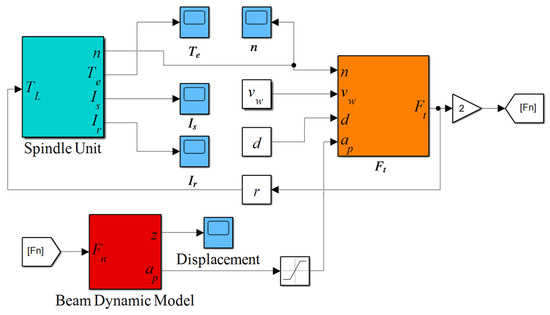
Figure 3.
Dynamic simulation model of the coupling system.

Table 2.
Parameters of dynamic simulation model.
Figure 4 shows the vibration response of the thin-walled workpiece under the grinding condition. It can be seen that the thin-walled workpiece shows obvious vibration in the grinding process and exhibits dynamic time-varying characteristics for moving grinding loads that vary with their grinding point, and the amplitude near the midpoint is the largest, which is obviously different from the ideal situation ignoring the elastic vibration of the thin-walled workpiece.
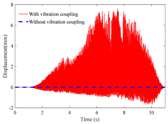
Figure 4.
Vibration response of thin-walled workpiece in the grinding process.
According to the above analysis, the elastic vibration of the thin-walled workpiece has an important influence on the fluctuations of the grinding depth and grinding force, which will affect the dynamic response characteristics of the grinding spindle directly. In order to analyze the electromechanical coupling dynamic characteristics of the grinding spindle with the vibration coupling of the thin-walled workpiece, the output speed, electromagnetic torque and rotor current waveforms of the grinding spindle are shown in Figure 5, Figure 6 and Figure 7, respectively. In the simulation process, the load begins to be applied at 1 s. Under the grinding load starting from 1 s, the spindle speed decreases while the electromagnetic torque and rotor current increase correspondingly, and this trend keeps a balance with the load torque. At the same time, the electromechanical coupling dynamic response characteristics of the grinding spindle are obviously different from the ideal constant load situation, when ignoring the vibration coupling, specifically the vibration coupling that enhances the fluctuations of the output speed, electromagnetic torque and rotor current. The results demonstrate the electromechanical coupling dynamic response characteristics of the grinding spindle under the vibration coupling of the thin-walled workpiece, which causes certain errors for the dynamic analysis and subsequent control, ignoring the vibration coupling effect of the thin-walled workpiece.
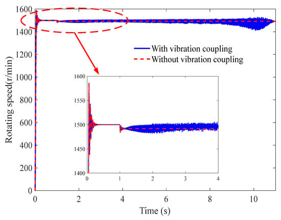
Figure 5.
Speed characteristic curves of the grinding spindle with vibration coupling of thin-walled workpiece.
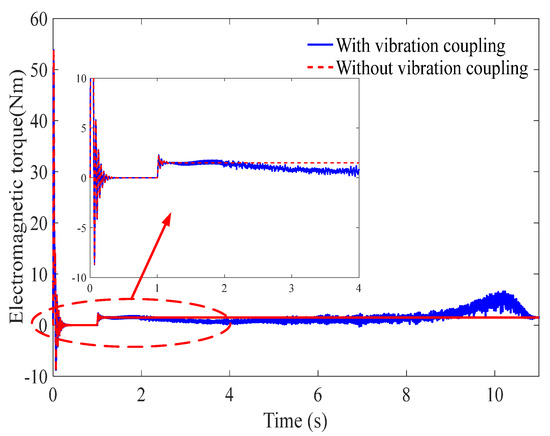
Figure 6.
Electromagnetic torque curves of the grinding spindle with vibration coupling of thin-walled workpiece.
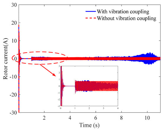
Figure 7.
Rotor current curves of the grinding spindle with vibration coupling of thin-walled workpiece.
4. Speed Adaptive Control of Grinding Spindle
According to the above analysis, in the grinding process, the thin-walled workpiece exhibits elastic vibration, while the grinding spindle conveys speed fluctuations. In other words, there is a certain coupling relationship between the elastic vibration and the speed fluctuations. In this section, according to the coupling relationship, a speed adaptive control system of the grinding spindle is designed based on the fuzzy PI controller to realize disturbance suppression of the speed fluctuations of the grinding spindle and the elastic vibration of the thin-walled workpiece.
The designed speed adaptive control system is shown in Figure 8. The design of the proposed fuzzy adaptive PI control strategy is composed of the combination of a fuzzy controller and a PI controller, which is more flexible and stable compared with a traditional PI control. The fuzzy adaptive PI controller takes error e and error change rate ec as input variables and ∆kp and ∆ki as output variables. The fuzzy domains of e and ec are [−3,3], and the membership function is shown in Figure 9. The membership function is shown in Figure 10. The fuzzy subsets of the input and output language variables ∆kp and ∆ki are negative large, negative medium, negative small, zero, positive small, middle and above board, which are denoted by NB, NM, NS, Z, PS, PM and PB, respectively. The fuzzy rules of ∆kp and ∆ki are shown in Table 3 and Table 4, respectively, which are obtained from previous engineering experience and experiments. The output surfaces of ∆kp and ∆ki obtained from this rule are shown in Figure 11 and Figure 12, respectively. As can be seen from Figure 11 and Figure 12, ∆kp and ∆ki are obtained by the joint action of e and ec, and the surface is close to continuous and changes smoothly, which indicates that the designed fuzzy adaptive PI controller has good dynamic performance.
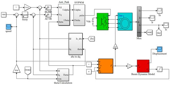
Figure 8.
Speed adaptive control system of grinding spindle under vibration coupling.
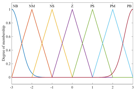
Figure 9.
Membership functions of input variables e and ec.
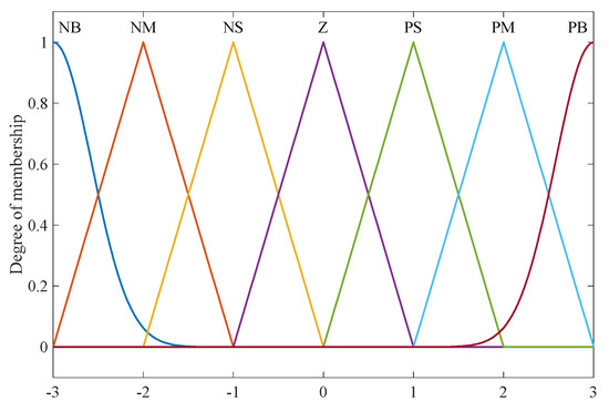
Figure 10.
Membership functions of output variables ∆kp and ∆ki.

Table 3.
Fuzzy control rules of ∆Kp.

Table 4.
Fuzzy control rules of ∆Ki.
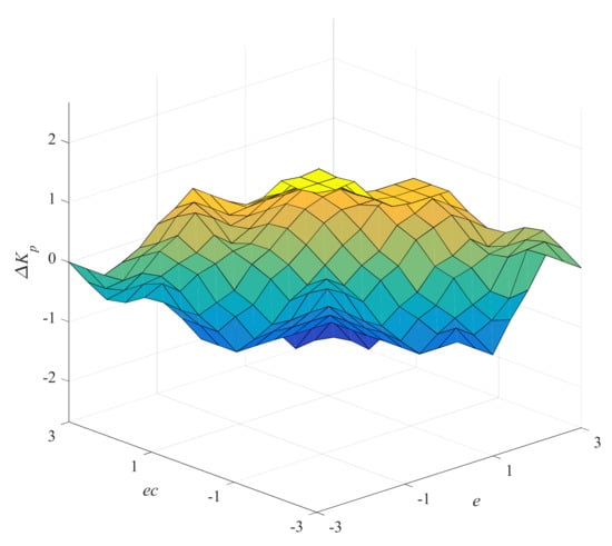
Figure 11.
Input–output relation diagram of ∆Kp.
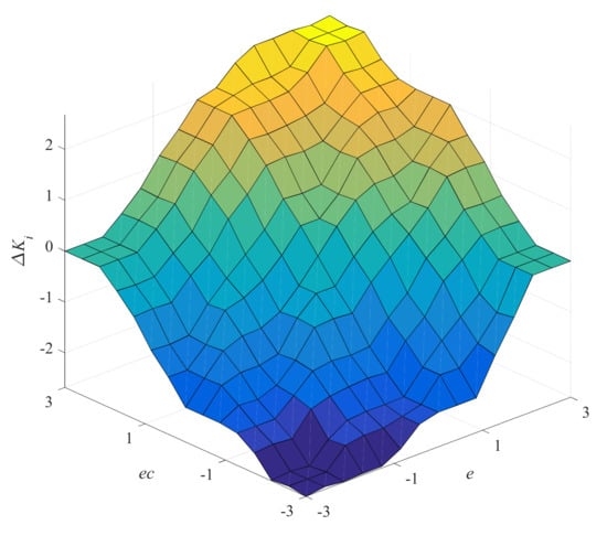
Figure 12.
Input–output relation diagram of ∆Ki.
Figure 13 shows the adaptive control effect of the grinding spindle speed under the coupling vibration of the thin-walled workpiece; it can be seen that the designed fuzzy adaptive PI controller can realize the stability of the grinding spindle speed under vibration coupling, which can quickly adjust the speed to an ideal constant speed and improve the robustness of the grinding system. At the same time, it can be seen from Figure 14 that the vibration of the thin-walled workpiece under speed adaptive control is relatively attenuated, which indicates that the designed fuzzy adaptive PI controller also has a certain suppression effect on the elastic vibration of the thin-walled workpiece with a reduction in vibration amplitude of about 38.5%.
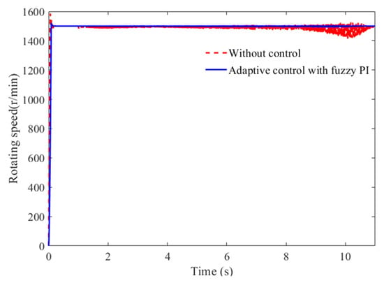
Figure 13.
Adaptive control of grinding spindle speed under vibration coupling with thin-walled workpiece.
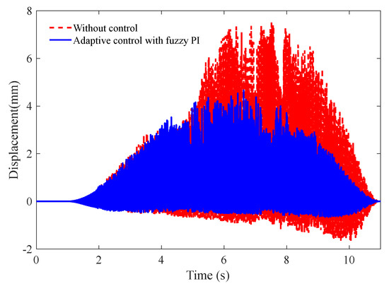
Figure 14.
Vibration suppression effect of thin-walled workpiece under speed adaptive control of grinding spindle.
In order to further verify the results obtained in this paper, a virtual prototype for experimental verification is conducted. We combined the control strategy and the virtual prototype model of the elastic thin-walled workpiece in ADAMS to build a co-simulation experimental system, in which the output grinding force of the control system is applied to the elastic thin-walled workpiece. At the same time, the vibration displacement of the elastic thin-walled workpiece is feedback to the control system, to verify the control effect. The virtual prototype model of the elastic thin-walled workpiece and the constructed co-simulation experimental system are shown in Figure 15 and Figure 16, respectively, and the co-simulation experimental results of the speed control of the grinding spindle and the vibration control of the elastic thin-walled workpiece are shown in Figure 17 and Figure 18, respectively. The co-simulation results of the virtual prototype can also verify the effectiveness of the control strategy proposed in this paper.

Figure 15.
The schematic diagram of co-simulation experiment based on virtual prototype.
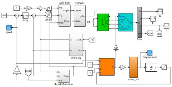
Figure 16.
The co-simulation experimental model of the adaptive control strategy.
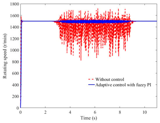
Figure 17.
Speed control results of grinding spindle in the co-simulation experiment.
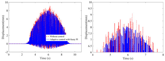
Figure 18.
Vibration control results of elastic thin-walled workpiece in the co-simulation experiment: (left) global; (right) locally enlarged.
5. Conclusions
This paper established the dynamic model of the grinding spindle and thin-walled workpiece coupling system, and the electromechanical coupling dynamic characteristics of the coupling system are revealed, which have guiding significance for the vibration control of the robotic grinding system. The conclusions can be obtained as follows:
- (1)
- the thin-walled workpiece has obvious vibration in the grinding process and exhibits dynamic time-varying characteristics for moving grinding loads that vary with the grinding point, which directly cause fluctuations of the grinding depth and grinding force and affect the dynamic response characteristics of the grinding spindle;
- (2)
- the electromechanical coupling dynamic response characteristics of the grinding spindle with the vibration coupling of thin-walled workpiece are obviously different from the ideal constant load condition, ignoring the vibration coupling of thin-walled workpiece, specifically the vibration coupling that obviously enhances the response fluctuations of the output speed, electromagnetic torque and rotor current; thus, ignoring the vibration coupling effect of the thin-walled workpiece causes certain errors for the dynamic analysis and subsequent control;
- (3)
- the proposed speed adaptive control of the grinding spindle based on the fuzzy PI controller can realize the stability of the grinding spindle speed under vibration coupling and has a certain suppression effect on the elastic vibration of the thin-walled workpiece, with a reduction in vibration amplitude of about 38.5%.
Author Contributions
Conceptualization, Y.L.; methodology, Y.L. and J.J.; software, Y.L. and D.T.; validation, Y.L. and D.T.; formal analysis, Y.L. and D.T.; investigation, Y.L., J.J. and D.T.; writing, Y.L. and D.T.; project administration, Y.L. and J.J.; funding acquisition, Y.L. and J.J. All authors have read and agreed to the published version of the manuscript.
Funding
This research was funded by the National Natural Science Foundation of China (No. 51805001), the Wuhu Science and Technology Project (No. 2022yf57 and No. 2022jc25), the Anhui Provincial Natural Science Foundation (No. 1908085QE193), the Natural Science Research Project of Higher Education of Anhui Province (No. KJ2019A0147), and a project funded by the China Postdoctoral Science Foundation (No. 2017M612060), Anhui Polytechnic University and the Jiujiang District Industrial collaborative Innovation Special Fund Project (2021cyxtb1).
Data Availability Statement
The data used in this article can be made available upon reasonable request. Please contact the first author, Y.L. (liuyufeiahpu@126.com).
Conflicts of Interest
The authors declare no conflict of interest.
References
- Rodriguez, A.; López De Lacalle, L.N.; Pereira, O.; Fernandez, A.; Ayesta, I. Isotropic finishing of austempered iron casting cylindrical parts by roller burnishing. Int. J. Adv. Manuf. Technol. 2020, 110, 753–761. [Google Scholar] [CrossRef] [PubMed]
- Pérez-Ruiz, J.D.; Marin, F.; Martínez, S.; Lamikiz, A.; Urbikain, G.; Lacalle, L. Stiffening near-net-shape functional parts of Inconel 718 LPBF considering material anisotropy and subsequent machining issues. Mech. Syst. Signal Process. 2022, 168, 108675. [Google Scholar] [CrossRef]
- Jimenez, A.; Bidare, P.; Hassanin, H.; Tarlochan, F.; Dimov, S.; Essa, K. Powder-based laser hybrid additive manufacturing of metals: A review. Int. J. Adv. Manuf. Technol. 2021, 114, 63–96. [Google Scholar] [CrossRef]
- Duan, Q.Q.; Wang, B.; Zhang, P.; Yang, K.; Zhang, Z.F. Improvement of notch fatigue properties of ultra-high CM400 maraging steel through shot peening. J. Mater. Res. 2017, 32, 1–9. [Google Scholar]
- Rodriguez, A.; Calleja, A.; Lacalle, L.; Pereira, O.; Laye, J. Burnishing of fsw aluminum Al–Cu–Li components. Metals 2019, 9, 260. [Google Scholar] [CrossRef]
- Ukar, E.; Lamikiz, A.; Lacalle, L.; Pozo, D.D.; Arana, J.L. Laser polishing of tool steel with co2 laser and high-power diode laser. Int. J. Mach. Tools Manuf. 2010, 50, 115–125. [Google Scholar] [CrossRef]
- González, H.; Pereira, O.; Fernández-Valdivielso, A.; López de Lacalle, L.N.; Calleja, A. Comparison of flank super abrasive machining vs. flank milling on inconel® 718 surfaces. Materials 2018, 11, 1638. [Google Scholar] [CrossRef]
- Klocke, F.; Schmitt, R.; Zeis, M.; Heidemanns, L.; Kerkhoff, J.; Heinen, D.; Klink, A. Technological and economical assessment of alternative process chains for blisk manufacture. Procedia CIRP 2015, 35, 67–72. [Google Scholar] [CrossRef]
- González, H.; Calleja, A.; Pereira, O.; Ortega, N.; López de Lacalle, L.N.; Barton, M. Super abrasive machining of integral rotary components using grinding flank tools. Metals 2018, 8, 24. [Google Scholar] [CrossRef]
- Lu, Y.; Xu, X.; Wang, L. Smart manufacturing process and system automation: A critical review of the standards and envisioned scenarios. J. Manuf. Syst. 2020, 56, 312–325. [Google Scholar] [CrossRef]
- Rodriguez, A.; González, M.; Pereira, O.; de Lacalle, L.N.L.; Esparta, M. Edge finishing of large turbine casings using defined multi-edge and abrasive tools in automated cells. Int. J. Adv. Manuf. Technol. 2021, 1–11. [Google Scholar] [CrossRef]
- Mohammadi, Y.; Ahmadi, K. Chatter in grinding with robots with structural nonlinearity. Mech. Syst. Signal Process. 2022, 167, 108523. [Google Scholar] [CrossRef]
- Kim, S.H.; Nam, E.; Ha, T.I.; Hwang, S.H.; Lee, J.H.; Park, S.H.; Min, B.K. Robotic Machining: A Review of Recent Progress. Int. J. Precis. Eng. Manuf. 2019, 2, 1629–1642. [Google Scholar] [CrossRef]
- Corral, J.; Pinto, C.; Campa, F.J.; Altuzarra, O. Surface location error of a parallel robot for routing processes. Int. J. Adv. Manuf. Technol. 2013, 67, 1977–1986. [Google Scholar] [CrossRef]
- Aviles, R.; Albizuri, J.; Ukar, E.; Lamikiz, A.; Aviles, A. Influence of laser polishing in an inert atmosphere on the high cycle fatigue strength of aisi 1045 steel. Int. J. Fatigue 2014, 68, 67–79. [Google Scholar] [CrossRef]
- Rodríguez, A.; López De Lacalle, L.N.; Fernández, A.; Braun, S. Elimination of surface spiral pattern on brake discs. J. Zhejiang Univ. Sci. A 2014, 15, 53–60. [Google Scholar] [CrossRef]
- Guo, Y.J.; Dong, H.Y.; Ke, Y.L. Stiffness-oriented posture optimization in robotic machining applications. Robot. Comput.-Integr. Manuf. 2015, 35, 69–76. [Google Scholar] [CrossRef]
- Lee, J.H.; Kim, S.H.; Min, B.K. Posture optimization in robotic drilling using a deformation energy model. Robot. Comput.-Integr. Manuf. 2022, 78, 102395. [Google Scholar] [CrossRef]
- Chen, C.; Peng, F.; Yan, R.; Li, Y.; Wei, D.; Fan, Z.; Tang, X.; Zhu, Z. Stiffness performance index based posture and feed orientation optimization in robotic milling process. Robot. Comput.-Integr. Manuf. 2019, 55, 29–40. [Google Scholar] [CrossRef]
- Zargarbashi, S.; Khan, W.; Angeles, J. Posture optimization in robot-assisted machining operations. Mech. Mach. Theory 2012, 51, 74–86. [Google Scholar] [CrossRef]
- Hintze, W.; Wenserski, R.V.; Junghans, S.; Junghans, S.; Mller, C. Finish machining of Ti6Al4V SLM components under consideration of thin walls and support structure removal. Procedia Manuf. 2020, 48, 485–491. [Google Scholar] [CrossRef]
- Wan, M.; Dang, X.B.; Zhang, W.H.; Yang, Y. Chatter suppression in the grinding process of the weakly-rigid workpiece through a moving fixture. J. Mater. Process. Technol. 2022, 299, 117293. [Google Scholar] [CrossRef]
- Guo, Y.; Dong, H.; Wang, G.; Ke, Y. Vibration analysis and suppression in robotic boring process. Int. J. Mach. Tools Manuf. 2016, 101, 102–110. [Google Scholar] [CrossRef]
- Wang, G.; Dong, H.; Guo, Y.; Ke, Y. Chatter mechanism and stability analysis of robotic boring. Int. J. Adv. Manuf. Technol. 2017, 91, 411–421. [Google Scholar] [CrossRef]
- Corral, J.; Pinto, C.; Campa, F.J.; Altuzarra, O. Dynamic behavior verification of a lightweight machine for routing. Int. J. Adv. Manuf. Technol. 2016, 86, 1151–1163. [Google Scholar] [CrossRef]
- Cao, H.; Bing, L.; He, Z. Chatter stability of milling with speed-varying dynamics of spindles. Int. J. Mach. Tools Manuf. 2012, 52, 50–58. [Google Scholar] [CrossRef]
- Shi, J.; Jin, X.; Cao, H. Chatter stability analysis in micro-milling with aerostatic spindle considering speed effect. Mech. Syst. Signal Process. 2022, 169, 108620. [Google Scholar] [CrossRef]
- Wang, C.; Zhang, X.; Liu, Y.; Cao, H.; Chen, X. Stiffness variation method for milling chatter suppression via piezoelectric stack actuators. Int. J. Mach. Tools Manuf. 2018, 124, 53–66. [Google Scholar] [CrossRef]
- Cen, L.; Melkote, S.N. CCT-based mode coupling chatter avoidance in robotic grinding. J. Manuf. Process. 2017, 29, 50–61. [Google Scholar] [CrossRef]
- Chen, C.; Peng, F.; Yan, R.; Fan, Z.; Li, Y.; Wei, D. Posture-dependent stability prediction of a grinding industrial robot based on inverse distance weighted method. Procedia Manuf. 2018, 17, 993–1000. [Google Scholar] [CrossRef]
- Nguyen, V.; Johnson, J.; Melkote, S. Active vibration suppression in robotic grinding using optimal control. Int. J. Mach. Tools Manuf. 2020, 152, 103541. [Google Scholar] [CrossRef]
- Yuan, L.; Sun, S.; Pan, Z.; Ding, D.; Gienke, O.; Li, W. Mode coupling chatter suppression for robotic machining using semi-active magnetorheological elastomers absorber. Mech. Syst. Signal Process. 2019, 117, 221–237. [Google Scholar] [CrossRef]
- Liu, D.; Luo, M.; Zhang, Z.; Hu, Y.; Zhang, D. Operational modal analysis based dynamic parameters identification in grinding of thin-walled workpiece. Mech. Syst. Signal Process. 2022, 167, 108469. [Google Scholar] [CrossRef]
- Wang, X.; Song, Q.; Liu, Z. Dynamic model and stability prediction of thin-walled component milling with multi-modes coupling effect. J. Mater. Process. Technol. 2020, 288, 116869. [Google Scholar] [CrossRef]
- Ma, J.; Li, Y.; Zhang, D.; Zhao, B.; Wang, G.; Pang, X. Dynamic response prediction model of thin-wall workpiece-fixture system with magnetorheological damping in milling. J. Manuf. Process. 2022, 74, 500–510. [Google Scholar] [CrossRef]
- Tian, W.; Ren, J.; Zhou, J.; Wang, D. Dynamic modal prediction and experimental study of thin-walled workpiece removal based on perturbation method. Int. J. Adv. Manuf. Technol. 2018, 94, 2099–2113. [Google Scholar] [CrossRef]
- Meng, J.; Chen, X.; He, Y. Electromechanical coupling Dynamic modeling of High speed motorized spindle’s motor-spindle subsystem. J. Mech. Eng. 2007, 43, 160–165. [Google Scholar] [CrossRef]
- Cao, H.; Holkup, T.; Altintas, Y. A comparative study on the dynamics of high speed spindles with respect to different preload mechanisms. Int. J. Adv. Manuf. Technol. 2011, 57, 871–883. [Google Scholar] [CrossRef]
- Zhang, S.J.; Yu, J.J.; To, S.; Xiong, Z.W. A theoretical and experimental study of spindle imbalance induced forced vibration and its effect on surface generation in diamond turning. Int. J. Mach. Tools Manuf. 2018, 133, 61–71. [Google Scholar] [CrossRef]
- Hou, Y.L.; Li, C.H.; Zhang, Q. Investigation of structural parameters of high speed grinder spindle system on dynamic performance. Int. J. Mater. Prod. Technol. 2012, 44, 92–114. [Google Scholar] [CrossRef]
- Xi, S.; Cao, H.; Chen, X. Dynamic modeling of spindle bearing system and vibration response investigation. Mech. Syst. Signal Process. 2019, 114, 486–511. [Google Scholar] [CrossRef]
- Jia, W.; Gao, F.; Li, Y.; Wu, W.W.; Li, Z.W. Nonlinear dynamic analysis and chaos prediction of grinding motorized spindle system. Shock. Vib. 2019, 2019, 1–10. [Google Scholar] [CrossRef]
- Guo, M.; Jiang, X.; Ding, Z.; Wu, Z.P. A frequency domain dynamic response approach to optimize the dynamic performance of grinding machine spindles. Int. J. Adv. Manuf. Technol. 2018, 98, 2737–2745. [Google Scholar] [CrossRef]
- Karagiannis, D.; Clayton, G.; Nataraj, C. Boundary control of harmonic disturbances on flexible cantilever beams using piezoelectric patch actuators. J. Vib. Control 2016, 22, 3916–3929. [Google Scholar] [CrossRef]
- Qiu, Z.; Wang, T.; Zhang, X. Sliding mode predictive vibration control of a piezoelectric flexible plate. J. Intell. Mater. Syst. Struct. 2020, 32, 65–81. [Google Scholar] [CrossRef]
- Abdeljaber, O.; Avci, O.; Inman, D. Active vibration control of flexible cantilever plates using piezoelectric materials and artificial neural networks. J. Sound Vib. 2016, 363, 33–53. [Google Scholar] [CrossRef]
- Jiang, X.; Zhao, G.; Lu, W. Vibration suppression of complex thin-walled workpiece based on magnetorheological fixture. Int. J. Adv. Manuf. Technol. 2020, 106, 1043–1055. [Google Scholar] [CrossRef]
- Ma, J.; Zhang, D.; Wu, B.; Luo, M.; Chen, B. Vibration suppression of thin-walled workpiece machining considering external damping properties based on magnetorheological fluids flexible fixture. Chin. J. Aeronaut. 2016, 29, 1074–1083. [Google Scholar] [CrossRef]
- Xiong, G.; Ding, Y.; Zhu, L. Stiffness-based pose optimization of an industrial robot for five-axis milling. Robot. Comput.-Integr. Manuf. 2019, 55, 19–28. [Google Scholar] [CrossRef]
- Janez, G.; Timi, K.; Karl, G.; Miran, B. Accuracy improvement of robotic machining based on robot’s structural properties. Int. J. Adv. Manuf. Technol. 2020, 108, 1309–1329. [Google Scholar] [CrossRef]
- Shen, N.; Guo, Z.; Li, J.; Tong, L.; Zhu, K. A practical method of improving hole position accuracy in the robotic drilling process. Int. J. Adv. Manuf. Technol. 2018, 96, 2973–2987. [Google Scholar] [CrossRef]
- Yin, C.; Zhou, Z. Concise and Quick Reference Manual of Machining Process; Chemical Industry Press: Beijing, China, 2017. [Google Scholar]
- Li, B.M.; Zhao, B.; Li, Q. Abrasives, Abrasive Tools and Grinding Techniques; Chemical Industry Press: Beijing, China, 2015. [Google Scholar]
- Wang, D.; Fan, H.; Xu, D.; Zhang, Y. Research on grinding force of ultrasonic vibration-assisted grinding of C/SiC composite materials. Appl. Sci. 2022, 12, 10352. [Google Scholar] [CrossRef]
- Zhang, D.K.; Li, C.; Jia, D.; Zhang, Y. Investigation into engineering ceramics grinding mechanism and the influential factors of the grinding force. Int. J. Control Autom. 2014, 7, 19–34. [Google Scholar] [CrossRef]
- Singiresu, S.R. Mechanical Vibration, 5th ed.; Pearson Education Inc.: New York, NY, USA, 2011. [Google Scholar]
- Wen, X.; Qiu, J.; Tao, J. Analytical Dynamics of Electromechanical Systems and Applications; Science Press: Beijing, China, 2007. [Google Scholar]
Disclaimer/Publisher’s Note: The statements, opinions and data contained in all publications are solely those of the individual author(s) and contributor(s) and not of MDPI and/or the editor(s). MDPI and/or the editor(s) disclaim responsibility for any injury to people or property resulting from any ideas, methods, instructions or products referred to in the content. |
© 2023 by the authors. Licensee MDPI, Basel, Switzerland. This article is an open access article distributed under the terms and conditions of the Creative Commons Attribution (CC BY) license (https://creativecommons.org/licenses/by/4.0/).