Abstract
The magnetic suspended dual-rotor system (MSDS) has the advantage of a high power density. The system can be used in high-speed rotating machinery. The major purpose of this study is to predict the unbalance response of the MSDS considering the nonlinear bearing characteristics of active magnetic bearings (AMBs). Firstly, the nonlinear bearing model was established by a non-linear magnetic circuit method (NMCM). The model considers magnetic flux leakage, magnetic saturation, and working position flotation accurately. Then, the dynamic model of the system was established by using the finite element method and solved by the Newmark-β method. Finally, the effects of external load, rotational speeds, and control parameters were studied. Axial trajectory diagrams, stability zone diagrams, and waterfall diagrams were employed to analyze the dynamic behaviors of the MSDS. The results indicate that the external load, rotational speeds, and control parameters have a significant impact on the unbalance response of the system. Super harmonics of rotational frequencies and their combined frequencies may be excited by heavy load conditions. Appropriate control parameters can suppress the nonlinear phenomena. The obtained results of this research will contribute to the design and fault diagnosis of MSDSs.
1. Introduction
Dual-rotor system is the core component of aeroengines and gas turbines. Active magnetic bearings (AMBs) have many advantages over conventional bearings, such as contactless operation, lubrication-free operation, and controllable dynamic bearing properties [1]. The substitution of AMB for mechanical bearings to support dual-rotor systems, namely, the magnetic suspended dual-rotor system (MSDS), can improve the power density of the system [2].
The traditional research on the dynamics of magnetic suspended bearing-rotor system were mostly based on the linearized AMBs bearing model, in which the nonlinear factors such as magnetic leakage and the saturation of AMBs were ignored, and the dynamics of system were studied based on the linearized bearing model near the equilibrium position [1]. However, in the dual rotor system, the load and vibration of the rotor is complex, the operation state of the rotor will no longer satisfy the assumption of ignoring those nonlinear factors, and the accurate response of the rotor system cannot be predicted by using the traditional, linearized AMBs bearing model. Therefore, the dynamics of the AMB rotor system with nonlinear bearing models of AMBs need to be studied.
Recently, the nonlinear bearing characteristics of AMBs have attracted the attention of researchers. C. Yu et al. and Cy A et al. considered the effects of magnetic leakage and magnetic saturation in hybrid magnetic bearings, respectively, using a dynamic magnetic circuit model [3,4]. A new mathematical modelling method of studying the suspension force was proposed by W. Zhang et al. The method is based on an exact segmentation of magnetic fields and enables the accurate calculation of edge flux and leakage coefficients [5]. Wang et al. proposed a non-linear magnetic circuit method (NMCM) to establish an analytical bearing capacity model for AMBs. The model considers the fringe flux, leakage flux, and the magnetic saturation. Experiments indicate that the accuracy of the model is high for different air gap lengths and eccentric distances [6]. Based on Wang et al., Wajnert et al. established an accurate bearing capacity model of hybrid magnetic bearings by using the NMCM and verified the efficiency of the model with experiments [7]. In general, due to magnetic leakage and magnetic saturation, the bearing characteristics of magnetic bearings exhibited significant nonlinearity. Accurate nonlinear bearing models of AMBs can be established by methods such as the NMCM.
Nonlinear factors can lead to more complex rotor dynamics, which is significantly different from the dynamic behaviors predicted using simple linearized models. Lu [8], Wang [9], Zhang [10,11], and Su et al. [12] studied the dynamic response of rotor system with nonlinear disturbances (e.g., shaft cracks, rotor rubbing, fluid exciting, and base shock). The results indicate that the system response is significant in the frequency domain, and many harmonic signals are excited in addition to the rotational frequency. Additionally, considering the nonlinearity of squeeze film damper and rolling bearing, the resonance characteristics of the system response become significantly different, and operating parameters such as rotational speed and load can affect the nonlinear behaviors of the system [13,14,15]. Compared to mechanical bearings, AMBs have different non-linearities, and the introduction of control laws can lead to richer dynamic behaviors. The nonlinear behaviors with large air gaps [16], time-varying stiffness [17,18,19], magnetic flux saturation and current saturation [20,21,22] are discussed, and it is shown that the control parameters can affect the nonlinear dynamic characteristics.
The motivation for this paper is to investigate the unbalance response of an MSDS considering nonlinear bearing characteristics of AMBs. Firstly, a non-linear bearing model for an AMB is established, Further, an MSDS dynamics model with a PID controller is built. Finally, the effects of external loads, rotational speed, and control parameters on the unbalanced response of the MSDS are analyzed.
2. System Model
A finite element model of an MSDS was designed for the study (Figure 1), where the dual-rotor system is discretized into nine nodes, including five nodes of the inner rotor and four nodes of the outer rotor, and the two coaxial rotors interlink through a mechanical inter-shaft bearing, and the rotors are supported by three AMBs.
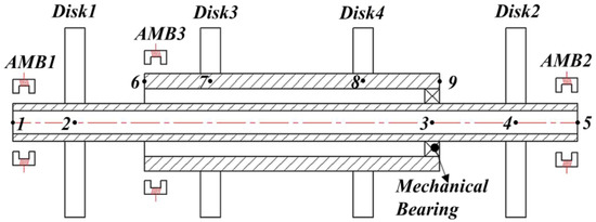
Figure 1.
Finite element model of the MSDS.
The Finite Element Method was used in this research to build the mathematical model of the MSDS. In the following research, the MSDS, in which the magnetic flux leakage and magnetic saturation of AMBs have been ignored and the electromagnetic forces are regarded as linear forces, is called the conventional MSDS. The opposite one is called the nonlinear MSDS. The effects of torsional vibration and axial vibration are ignored; only the freedom of radial vibration is considered, and the effects of the rotors’ gravity on the system are not considered. Moreover, the inter-shaft bearing is expressed as a linear spring and viscous damping. The main parameters of the structure are shown in Table 1.

Table 1.
The main parameters of the MSDS.
2.1. Magnetic Bearing Modeling
In this research, an eight-pole AMB with differential drive mode was used, the basic control loop in the y direction is shown in Figure 2. A PID strategy was applied to the controller, where Ib and Ic are the bias and control currents of the coil, respectively, and g0 is the air-gap length. The power amplifier Aa = 0.6; the displacement sensor As = 800.
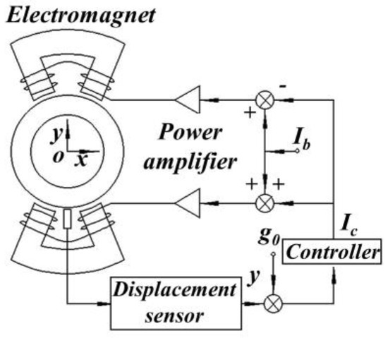
Figure 2.
Basic control loop.
To consider the effects of the nonlinear factors on AMBs in this research, electromagnetic forces were applied to the system as external forces. Therefore, the discussion is divided into two cases.
(a) The nonlinear electromagnetic force model: Based on the NMCM, which divided the magnetic field as shown in Figure 3a, the flux areas correspond to the magnetic resistance of the air gap, leakage, yoke, poles, and rotor (corresponding to Rg, Rk, Ry, Rp, and Rr, respectively). Then, the equivalent magnetic circuit (EMC) for one pole pair was obtained, as shown in Figure 3b, and the expression for the electromagnetic force in the x direction was deduced [6]
where, μ0 is the permeability of vacuum; α is the angle between the central lines of the pole and pole pair, α = π/8; Ap is the sectional area of the stator poles; N is the coil turn; Φ1 and Φ3 are the magnetic flux crossing the air gaps between the pole pairs and the rotors on the right and left, respectively.
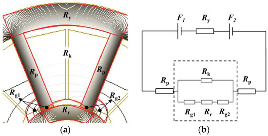
Figure 3.
The nonlinear electromagnetic force modeling process by using NCMC. (a) Magnetic field division. (b) EMC for one pole pair based on NMCM.
The electromagnetic force can be obtained after calculating each magnetic resistance value. Therefore, the NMCM was used to model and solve individual reluctances.
The air-gap magnetic resistance model is shown in Figure 4a. According to the magnetic flux distribution, the air-gap magnetic flux can be divided into edge flux tube, a, and main flux tube, b. Using a calculation, the permeability of both of them can be obtained, and Rg can be further calculated. Similarly, the magnetic flux of the leakage magnetic resistance model can be divided into regions 1, 2, and 3, as shown in Figure 4b. After calculating the permeability of each region, Rk can be calculated. In the calculation of Ry, Rp, and Rr, the effects of variation in magnetic permeability of soft magnetic materials are considered by using a power function to fit the B–H curve. The soft magnetic material B–H curve fit is shown in Figure 4c.

Figure 4.
Each reluctance calculation by using NMCM. (a) The air gap reluctance model; (b) the leakage reluctance model; (c) the magnetization curve points of soft magnetic materials and their fitting curve.
The same method can be used to obtain the electromagnetic force in the y direction.
(b) The conventional electromagnetic force model: Factors such as magnetic flux leakage and magnetic saturation on the bearing characteristics of AMBs were not considered. Therefore, in Figure 4, Ry, Rp, Rr, and Rk are ignored, and only the air-gap reluctances exist. Additionally, the AMB worked in a linear range, and the linearized electromagnetic force in a certain direction (such as x direction) is given by [23].
where, kx and ki are the displacement stiffness and current stiffness of the AMBs, respectively.
Based on Equations (1) and (3), the electromagnetic force of the AMB under conventional and nonlinear conditions can be obtained. For g0 = 2.0 mm, the bearing capacity curves calculated by the two electromagnetic force models and finite element method (FEM) are shown in Figure 5.
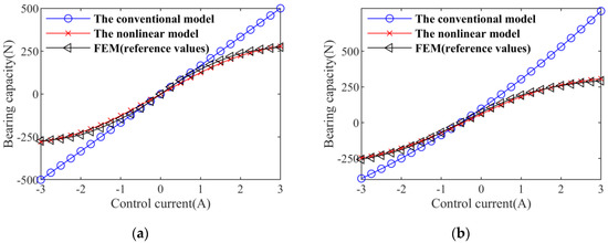
Figure 5.
Bearing capacity curves. (a) e = 0; (b) e = 20%.
In Figure 5, e is the ratio of radial eccentricity to normal air-gap length. The results of the nonlinear electromagnetic force model and FEM are in good agreement, and these two results are obviously different from those of the linear electromagnetic force model, especially when the control current was large.
2.2. Dynamical Equations of the MSDS
In Figure 1, the shaft element is described by the Euler–Bernoulli beam element, which has four degrees of freedom at each node, including two translations and two rotations. The generalized displacement vectors of the inner rotor are
where xk and yk (k = 1, 2, ..., 5) denote translations of notes 1–5, while θyk and θxk (k = 1, 2, ..., 5) denote the rotations of nodes 1–5, respectively.
Then, the motion equations of the inner rotor can be expressed as
where MI, Ji, and Ki are the mass, polar rotational inertial, and stiffness matrices of the inner rotor system, respectively, and ωi is the rotation speed of the inner rotor.
Similarly, the motion equations of the outer rotor are
where Mo, Jo, and Ko are the mass, polar rotational inertial, and stiffness matrices of the outer rotor system, respectively. ωo is the rotation speed of the outer rotor.
Based on the above analysis, the generalized displacement of the dual-rotor system can be further express as
Therefore, the motion equations of the system can be expressed as
where M, C, and K are the total mass, damping, and stiffness matrices of the system, respectively. F is the external incentive force vector.
where fa is the electromagnetic force vector; fq is the other external incentives vector. In addition, the stiffness and damping of the inner-shaft bearing should be added to the corresponding nodes.
Secondly, the electromagnetic forces of the AMBs should be added to the corresponding nodes.
where F is the generalized external force vector after considering the AMBs, F0 is the generalized external force vector without considering the AMBs, and fx,k and fy,k are the electromagnetic forces in the x and y directions of the kth node, respectively.
3. Model Validation
Based on the published results in [24], the established dynamic model was verified. When the AMBs are worked in a linear interval, the nonlinear factors have little influence on the bearing characteristics, which can be ignored, and the dynamic responses of the two systems are basically consistent in this moment [17]. A comparison between the numerical simulation and experimental results in [24] was conducted.
The finite element model of the dual-rotor system in reference is shown in Figure 6.
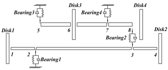
Figure 6.
Yang’s finite element model of the dual-rotor system [24].
According to the dual-rotor structure in the literature [24], mechanical bearings 1, 3, and 4 were replaced by AMBs, but the other structural parameters of the rotor system remain unchanged. The replaced dual-rotor system is an MSDS, and the structure parameters of the AMBs are shown in Table 2.

Table 2.
Structure parameters of AMBs.
To ensure that the bearing characteristics of the system remain unchanged after replacement, the control parameters are KP = 50, KI = 0.001, and KD = 0.027. At ωi = 252.6 rad/s and ωo = 301.2 rad/s, the unbalanced response of disk 1 in the vertical direction is shown in Figure 7. By comparing the results in Figure 7, it can be seen that the numerical results are in good agreement with the experimental results in [18].

Figure 7.
Displacement response of the dual-rotor system (ωi = 252.6 rad/s; ωo = 301.2 rad/s). (a) Yang’s experimental result; (b) numerical result of the conventional MSDS; (c) numerical result of the nonlinear MSDS.
At ωi = 184.1 rad/s and ωo = 276.1 rad/s, a frequency diagram of the unbalance response of disk 1 in the vertical direction is shown in Figure 8. It can be seen that the numerical calculated frequency components have a good consistent with the experimental results [18], except for the amplitude of frequency components, which are mainly related to the position of unbalance and the initial conditions.

Figure 8.
Displacement response of the dual-rotor system (ωi = 184.1 rad/s; ωo = 276.1 rad/s). (a) Yang’s experimental result; (b) numerical result of the conventional MSDS; (c) numerical result of the nonlinear MSDS.
From the above comparison results, the numerical results have a good agreement with the experimental results, and the dynamic models of the MSDS established in this research are correct.
4. Unbalance Response Analysis
According to [14], the load has a great influence on the bearing characteristics of AMBs; when the rotor system is subjected to a large external load, the AMBs will be deviated from the linear working interval and present strong nonlinear features, then the unbalance response of the rotor system will also tend to be complex. In this research, the dynamic characteristics of the nonlinear MSDS in Figure 1 are discussed by applying loads to the inner and outer rotors’ disks, respectively.
4.1. The Effect of Load on the System
To explore the effect of inner rotor’s loaded on unbalance response of the nonlinear MSDS with the control parameters and operation parameters KP = 40, KI = 100, KD = 0.05, ωi = 200 rad/s, rs = 1.2, and g0 = 2.0 mm, the stable unbalance response was analyzed by the Newmark-β method.
When the disk 1 was non-loaded, the time-domain response, shaft center trajectory, and frequency response of the two systems at disk 1 were calculated and are shown in Figure 9.
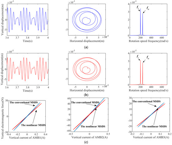
Figure 9.
Unbalanced responses of the disk 1 (ωi = 200 rad/s, FL = 0 N). (a) Unbalanced response of the conventional MSDS. (b) Unbalanced response of the nonlinear MSDS. (c) Bearing capacity curves of AMB 1, AMB 2, and AMB 3.
It can be seen from Figure 9a,b that the unbalance response of those two systems are basically identical, as there are only rotation frequencies fi and fo in the spectrum diagram. In Figure 9c, the bearing force of each AMB in the nonlinear MSDS is smaller than that of the conventional MSDS under the same current.
When disk 1 was loaded with 200 N in the vertical direction, the unbalance responses of the two systems were calculated and are shown in Figure 10.
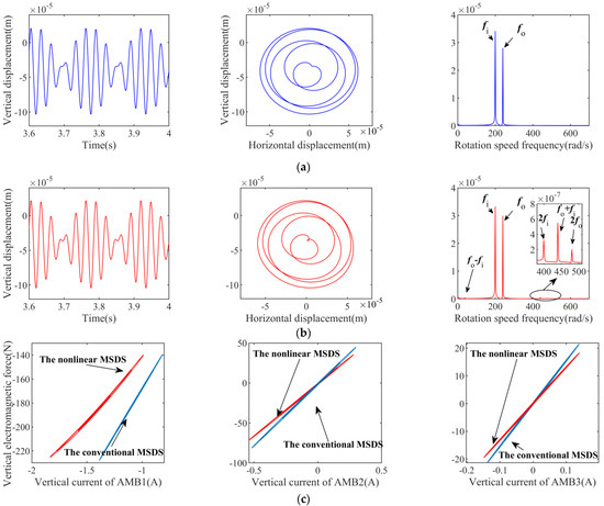
Figure 10.
Unbalanced responses of the disk 1 (ωi = 200 rad/s, FL = 200 N). (a) Unbalanced response of the conventional MSDS. (b) Unbalanced response of the nonlinear MSDS. (c) Bearing capacity curves of AMB 1, AMB 2, and AMB 3.
It can be seen from Figure 10 that the unbalance response of the conventional MSDS is basically unchanged after the load is applied, and only the rotor is not fully returned to the balance position due to the flexibility of the rotor and the overall stiffness of the system. Additionally, in the nonlinear MSDS, the vertical current and electromagnetic forces of AMB 1 increased significantly, and a nonlinear relationship between the electromagnetic force and the movement of the rotor presented, which lead to significance changes in the unbalance response of the system. In Figure 10b, it can be seen that not only frequencies fi and fo appear, but also more combined frequency components appear in the spectrum diagram of the nonlinear MSDS, whose frequency values can be expressed as mfo ± nfi (m, n = 0, 1, 2, ...).
Figure 11 shows the shaft center trajectory of the inner rotor in the two systems. It can be seen that the shaft center trajectory at each node of two systems is also different, especially near the AMB 1. This phenomenon is also caused by the nonlinear bearing characteristics of the AMBs.
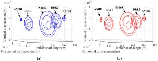
Figure 11.
Shaft center trajectory diagrams of the inner rotor (ωi = 200 rad/s; FL = 200 N). (a) The conventional MSDS, (b) the nonlinear MSDS.
In addition, Figure 12 shows the current responses of AMB 1 in the vertical direction when disk 1 was loaded with 200 N. It can be seen that the maximum current value of the nonlinear MSDS is closer to the system’s designed limit (−3A). Moreover, the amplitude of current in the nonlinear MSDS is larger than that in the conventional MSDS.
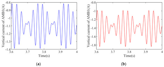
Figure 12.
Current in the vertical direction of the AMB 1 (ωi = 200 rad/s; FL = 200 N). (a) The conventional MSDS. (b) The nonlinear MSDS.
The waterfall plots of frequency responses of the two systems under different loads are shown in Figure 13.

Figure 13.
Waterfall plots of frequency responses under different load. (a) At disk 1 of the conventional MSDS. (b) At disk 1 of the nonlinear MSDS. (c) At disk 4 of the nonlinear MSDS.
In Figure 13a, only rotation frequencies fi and fo are found with the increase in the load in the conventional MSDS. However, in the nonlinear MSDS, as the load increases, the nonlinear bearing characteristics of the AMBs become more severe, and some combined frequency components appear in the system, such as fo – fi, fo + fi, 2fi, and 2fo. Additionally, the larger the load is, the more combined frequency components that will appear. It can be seen in Figure 13c that the same situation occurs for disk 4: with the increase in the load, more combined frequency components appear. The unbalance responses of other disks also show the same phenomenon as disk 1 does, which are not shown here.
From the above analysis, in the nonlinear MSDS, when the system is attached to a large external load, the AMBs show clear nonlinear bearing characteristics, and the response of the dual-rotor system appears to be obviously nonlinear, and the frequency response components of the system become more complex.
When the outer rotor’s disks are loaded, the responses of the system are similar, which are not shown in here. Because the response laws of the four disks are similar, only the response at disk 1 was analyzed in the following research.
4.2. The Effect of Operation Parameters
With the control parameters KP = 40, KI = 100, and KD = 0.05, when rs = 1.2 and FL = 200 N, the waterfall plots of frequency responses at disk 1 of the two systems under different rotation speeds were calculated and are shown in Figure 14.
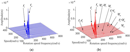
Figure 14.
Waterfall plots of frequency responses of the disk 1 under different rotation speeds. (a) The conventional MSDS. (b) The nonlinear MSDS.
In the conventional MSDS, only rotation frequencies fi and fo appear in the waterfall diagram under different rotation speed. However, it can be seen from Figure 14b that other combined frequency components also appear in the nonlinear MSDS, but the combined frequency components will not always be excited by the load. When the rotation speed is in a range from [150, 200] rad/s to [270, 320] rad/s, the vibration of the system increases and the nonlinear bearing characteristics of the AMBs in this range become more severe; more combined frequency components appear in the waterfall diagram. The results mean that the rotation speed and external load have a large influence on the responses of the MSDSs, and the effect is reflected not only in the frequency components of rotor steady-state responses, but also in the stability of the system.
With the same control parameters as Figure 14, when rs = 1.2, Figure 15 shows the stable operation area of the two systems when ωi is [100, 400] rad/s.
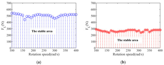
Figure 15.
The stable operation area of the two systems under load conditions. (a) The conventional MSDS. (b) The nonlinear MSDS.
It can be seen in Figure 15, the maximum load capacity of the system varies with the rotation speed, which indicates that the stable operation area of the system is related to the rotation speed. Moreover, the stable area of the nonlinear MSDS is smaller than that of the conventional MSDS under the same operating conditions, which means the stability of the nonlinear MSDS is worse.
From above analysis, the nonlinear responses of the MSDS are determined by the external load and rotation speed, and only when the amplitude of the vibration responses is large will the combined frequency components appear. Additionally, the stability of the nonlinear MSDS is worse than that of the conventional MSDS under the same operating conditions.
4.3. The Effect of Control Parameters
When the structural parameters and operating conditions of the MSDS are determined, the system response can be changed by adjusting the control parameters. With heavy load conditions, the effect of the PID control parameters on the system nonlinear unbalance response is investigated in this section
With the same operating parameters as Figure 14, when KI = 100 and ωi = 200 rad/s, the frequency response waterfall plots of the system at disk 1 at different KP or KD values are shown in Figure 16, respectively.
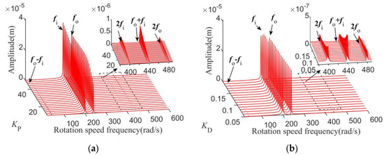
Figure 16.
Waterfall plots of frequency responses of disk1 under different control parameters. (a) KP; (b) KD.
In Figure 16a, the fo − fi component of the vibration responses is obvious when KP is small; with the increase in KP, the amplitude of the system increases, more frequency combined components appear, and the 2fi, fo + fi and 2fo components of the vibration responses become larger.
It can be seen from Figure 16b that when KD is small, the vibration suppression ability of the system is limited and the nonlinear bearing characteristics of AMBs become serious; the rotation frequencies 2fi and fo + fi are obvious in the waterfall diagram. The response amplitudes of these frequency components decrease with the increase in KD, meanwhile, the nonlinear bearing characteristics are minimized.
Therefore, control parameters KP and KD can affect the dramatic level of the non-linear response characteristics of the system under heavy loads. A larger KP and a smaller KD induce more combined frequency components and increase the amplitude of the components, making the unbalance response of the system more complex.
The effect of KI on the system response is mainly reflected in the low-frequency segment, and it can be ignored in the high-frequency segment; the research results are not shown here.
5. Conclusions
In this paper, the unbalance response of an MSDS based on the nonlinear bearing characteristics of AMBs was investigated. A finite element model of the system was built, and the Newmark-β method was employed to obtain the stable unbalance response of the system. Accordingly, the time-domain response, shaft center trajectory, and frequency response of the system with different operation parameters and control parameters were studied. The results indicated that the external load, speed, and control parameters have influences on the unbalance response of the system. The specific conclusions are as follows:
- (1)
- Combination frequencies (mfo ± nfi) may exist in the responses of the nonlinear MSDS under heavy loading conditions, which could excite the nonlinear bearing characteristics of the AMBs, and the effects of the inner and outer rotors’ disks that are loaded are basically identical. Moreover, the stability of the nonlinear MSDS is worse than that of the conventional MSDS under the same operating conditions.
- (2)
- KP has an influence on the amplitude of the nonlinear system; when the amplitude of the system becomes larger, the unbalance response of the system becomes more complex, and a small KD will lead to more combination frequencies. The results obtained in this paper may contribute to the construction of models based on the nonlinear bearing characteristics of AMBs and restraining the negative effect of nonlinear bearing characteristics on the system.
Author Contributions
N.W.: conception of the study, propose theory and method, supervisor; M.L.: literature search and writing; J.Y.: software, drawing, data collection and processing, writing—original draft; P.G.: software, drawing; H.W.: data interpretation and analysis. All authors have read and agreed to the published version of the manuscript.
Funding
This research was funded by National Natural Science Foundation (Grant No. 51975427) and Shenzhen Science and Technology Plan Project (Grant No. JCYJ20190809150603586).
Data Availability Statement
The data used to support the findings of this study are available from the corresponding author upon request.
Conflicts of Interest
The authors declare that there are no conflict of interest regarding the publication of this paper.
References
- Maslen, E.H.; Schweitzer, G.; Bleuler, H.; Cole, M.; Traxler, A. Magnetic Bearings—Theory, Design, and Application to Rotating Machinery; Springer: Berlin/Heidelberg, Germany, 2009. [Google Scholar]
- Wang, D.X.; Wang, N.X.; Chen, K.S.; Ye, C. Dynamic Characteristics of Magnetic Suspended Dual-Rotor System by Riccati Transfer Matrix Method. Shock. Vib. 2019, 2019, 9843732. [Google Scholar] [CrossRef]
- Yu, C.M.; Deng, Z.Q.; Mei, L.; Peng, C.; Cao, X.; Chen, S.S.; Ding, Q. Evaluation Criteria of Material Selection on 3-DOF Hybrid Magnetic Bearing. IEEE Trans. Ind. Appl. 2021, 57, 4733–4744. [Google Scholar] [CrossRef]
- Yu, C.; Deng, Z.; Mei, L.; Peng, C.; Cao, X. Multiobjective optimization of 3-DOF magnetic bearing considering eddy current effects and saturation. Mech. Syst. Signal Process. 2023, 182, 109538. [Google Scholar] [CrossRef]
- Zhang, W.Y.; Yang, H.K.; Cheng, L.; Zhu, H.Q. Modeling Based on Exact Segmentation of Magnetic Field for a Centripetal Force Type-Magnetic Bearing. IEEE Trans. Ind. Electron. 2020, 67, 7691–7701. [Google Scholar] [CrossRef]
- Wang, D.X.; Wang, N.X.; Ye, C.; Chen, K.S. Research on analytical bearing capacity model of active magnetic bearings based on magnetic saturation. IET Electr. Power Appl. 2017, 11, 1548–1557. [Google Scholar] [CrossRef]
- Wajnert, D.; Tomczuk, B. Nonlinear magnetic equivalent circuit of the hybrid magnetic bearing. Compel-Int. J. Comput. Math. Electr. Electron. Eng. 2019, 38, 1190–1203. [Google Scholar] [CrossRef]
- Lu, Z.Y.; Hou, L.; Chen, Y.S.; Sun, C.Z. Nonlinear response analysis for a dual-rotor system with a breathing transverse crack in the hollow shaft. Nonlinear Dyn. 2016, 83, 169–185. [Google Scholar] [CrossRef]
- Wang, D.; Wang, N.; Chen, K. Fixed-point Rubbing Characteristics of Magnetic Suspended Dual-rotor Systems. China Mech. Eng. 2021, 32, 1686–1699. [Google Scholar]
- Zhang, S.Y.; Zhou, J.; Wu, H.T.; Zhang, Y. Dynamic Analysis of Active Magnetic Bearing Rotor System Considering Alford Force. J. Vib. Eng. Technol. 2021, 9, 1147–1154. [Google Scholar] [CrossRef]
- Zhang, S.Y.; Zhou, J.; Han, X.M.; Ma, Y.C. Analysis of Nonlinear Characteristics and the Factors Affecting the Operation of the Active Magnetic Bearings Rotor System Considering Alford Force. Appl. Comput. Electromagn. Soc. 2022, 37, 253–261. [Google Scholar] [CrossRef]
- Su, Y.X.; Gu, Y.P.; Keogh, P.S.; Yu, S.Y.; Ren, G.X. Nonlinear dynamic simulation and parametric analysis of a rotor-AMB-TDB system experiencing strong base shock excitations. Mech. Mach. Theory 2021, 155, 104071. [Google Scholar] [CrossRef]
- Yi, H.; Hou, L.; Gao, P.; Chen, Y. Nonlinear resonance characteristics of a dual-rotor system with a local defect on the inner ring of the inter-shaft bearing. Chin. J. Aeronaut. 2021, 34, 110–124. [Google Scholar] [CrossRef]
- Gao, P.; Chen, Y.S.; Hou, L. Nonlinear thermal behaviors of the inter-shaft bearing in a dual-rotor system subjected to the dynamic load. Nonlinear Dyn. 2020, 101, 191–209. [Google Scholar] [CrossRef]
- Wang, F.; Luo, G.H.; Yan, S.; Cui, H.T. A Comparison Study on Co- and Counterrotating Dual-Rotor System with Squeeze Film Dampers and Intermediate Bearing. Shock. Vib. 2017, 2017, 5493763. [Google Scholar] [CrossRef]
- Ji, J.C.; Hansen, C.H. Non-Linear Oscillations of a Rotor in Active Magnetic Bearings. J. Sound Vib. 2001, 240, 599–612. [Google Scholar] [CrossRef]
- Zhang, G.; Xi, G. Vibration Control of a Time-Delayed Rotor-Active Magnetic Bearing System by Time-Varying Stiffness. Int. J. Appl. Mech. 2022, 14, 2250007. [Google Scholar] [CrossRef]
- Zhang, W.; Wu, R.Q.; Siriguleng, B. Nonlinear Vibrations of a Rotor-Active Magnetic Bearing System with 16-Pole Legs and Two Degrees of Freedom. Shock. Vib. 2020, 2020, 5282904. [Google Scholar] [CrossRef]
- Wu, R.Q.; Zhang, W.; Yao, M.H. Nonlinear dynamics near resonances of a rotor-active magnetic bearings system with 16-pole legs and time varying stiffness. Mech. Syst. Signal Process. 2018, 100, 113–134. [Google Scholar] [CrossRef]
- Zhang, X.S.; Fan, T.P.; Sun, Z.; Zhao, L.; Yan, X.S.; Zhao, J.L.; Shi, Z.G. Nonlinear Analysis of Rotor-AMB System with Current Saturation Effect. Appl. Comput. Electromagn. Soc. J. 2019, 34, 557–566. [Google Scholar]
- Sun, Z.; Zhang, X.; Fan, T.; Yan, X.; Zhao, J.; Zhao, L.; Shi, Z. Nonlinear dynamic characteristics analysis of active magnetic bearing system based on cell mapping method with a case study. Mech. Syst. Signal Process. 2019, 117, 116–137. [Google Scholar] [CrossRef]
- Kang, K.; Palazzolo, A. Homopolar Magnetic Bearing Saturation Effects on Rotating Machinery Vibration. IEEE Trans. Magn. 2012, 48, 1984–1994. [Google Scholar] [CrossRef]
- Soni, T.; Dutt, J.K.; Das, A.S. Dynamic behavior and stability of energy efficient electro-magnetic suspension of rotors involving time delay. Energy 2021, 231, 120906. [Google Scholar] [CrossRef]
- Yang, Y.; Cao, D.; Yu, T.; Wang, D.; Li, C. Prediction of dynamic characteristics of a dual-rotor system with fixed point rubbing—Theoretical analysis and experimental study. Int. J. Mech. Sci. 2016, 115, 253–261. [Google Scholar] [CrossRef]
Disclaimer/Publisher’s Note: The statements, opinions and data contained in all publications are solely those of the individual author(s) and contributor(s) and not of MDPI and/or the editor(s). MDPI and/or the editor(s) disclaim responsibility for any injury to people or property resulting from any ideas, methods, instructions or products referred to in the content. |
© 2023 by the authors. Licensee MDPI, Basel, Switzerland. This article is an open access article distributed under the terms and conditions of the Creative Commons Attribution (CC BY) license (https://creativecommons.org/licenses/by/4.0/).