Article

Attitude Control of Vehicle Based on Series Active Suspensions

1
School of Management Science and Information Engineering, Jilin University of Finance and Economics, Changchun 130117, China
2
State Key Laboratory of Automotive Simulation and Control, Jilin University, Changchun 130012, China
*
Authors to whom correspondence should be addressed.
Actuators 2023, 12(2), 67; https://doi.org/10.3390/act12020067
Submission received: 11 January 2023 / Revised: 29 January 2023 / Accepted: 2 February 2023 / Published: 5 February 2023

Abstract

:
When vehicles with traditional passive suspension systems are driving in complex terrain, large swing and vibrations of the car body make passengers and goods uncomfortable and unstable, even at very low-speed conditions. Considering the actual need for intelligent resource exploration in the sustainable economy, visual-based perception and localization systems of unmanned vehicles still cannot handle the sensor noise coursed by large body motions. In order to improve the stability and safety of vehicles in complex terrain, an attitude control system is proposed for mainly eliminating the external body motions of the vehicle by using series active suspensions. A model predictive control method considered the differences between the simulated and real vehicle, and the performance restrictions of actuators are used to design the attitude controller for reducing the heaving, pitching, and rolling motions of the vehicle. After simulations and real car tests, the results show that the proposed attitude controller can significantly improve the attitude stability of vehicles in harsh terrain.

1. Introduction

Intelligent vehicles with high mobility, high passability, and low environmental footprint have a wide range of application prospects in the fields of resource exploration, post-disaster search, rescue, and fire extinguishing in the sustainable economy. It is difficult for vehicles with traditional passive suspensions to maintain the attitude stability of the car body, which seriously affects the comfort, safety, and sensitivity of passengers, goods, and intelligent payload.
In the past few decades, active suspension systems have been studied for improving ride comfort and handling capability [1]. The optimal controller using integral action for the suspension deflection considerably reduced rolling, pitching, and heaving motions of the car body and at the same time adjusted the ground-grasping forces of each wheel for different road disturbances, especially on sharp corners and during braking maneuvers [2]. The attitude tracking controller can help the car body tilt inward in cornering, lean forward when accelerating and backward when decelerating. In this way, ride comfort can be improved by eliminating the centrifugal forces acting on passengers. Along with ride comfort, the active attitude motion of the car body will enhance the road-holding capability and reduce the chance of rollover by balancing the ground grasping forces on each wheel in cornering, braking, and accelerating [3]. In order to eliminate the unpleasant lateral and longitudinal accelerations acting on passengers, the proposed attitude control often requires large ideal roll and pitch angles that surpass the angles that can be attained in actual car body motion. Due to the limitation of suspension spaces, an active seat system is added to the car body in order to accommodate angles larger than the available body angle to further improve ride comfort [4]. Considering the improved road-holding capability and the coupling effect of body attitude motion and yaw motion, the attitude controller combined with a steering controller to produce a synergistic effect on ride comfort, handling, and safety [5].
Existing research of active suspension systems has shown a huge potential for attitude motion control of ground vehicles. The active system can control the body attitude according to the terrain information for eliminating large swings and vibrations of the car body in a harsh terrain situation [6,7,8]. In the robotics field, research on body-level control and body motion control on unmanned multi-joints robots has been increasing [9,10,11,12,13,14,15]. However, the problem of high energy consumption and low reliability of parallel active suspensions and joint-actuators still limit their utilization. As one of the limited bandwidth active suspensions, a series active suspension which includes actuators and vibrators in the form of a series has a simpler structure, lower design costs, and a larger attitude adjustment range than a parallel and hybrid active suspension. Therefore, designing an innovative vehicle with series active suspensions has good research value. Konieczny et al. investigated performances of slow and full active suspensions. Based on a quarter-vehicle model, active suspension control algorithms were analyzed [16]. Westhuizen et al. proposed using series active suspensions to eliminate body rolling so as to reduce the possibility of a rollover. A verified ADAMS model is used to simulate the double lane change maneuver at a speed of 60 km/h. Under relatively low energy needs, it can achieve a significant reduction in body rolling [17]. Ma et al. designed a wheel-legged all-terrain vehicle based on series active suspensions. An attitude closed-loop control strategy was verified by both the simulated model and the real vehicle. In order to reduce the impact of rough terrain on stability and ride comfort, the attitude control algorithm was further verified [18,19].
Many scholars have studied the control of model predictive control (MPC) on suspension and body attitude. Erik et al. propose a feasible method for analyzing the effect of the maximum force and maximum rate of change of the actuator on the attainable ride comfort. In this method, the model predictive controller is used to eliminate the influence of feedback controller performance, and the wheel load and suspension travel are constrained [20]. Guan et al. proposed a comprehensive path and attitude control strategy for articulated vehicles for varying vehicle conditions to improve the lateral stability of articulated vehicles based on model predictive control (MPC) [21]. In addition, A stability control system is proposed to improve vehicle stability based on model predictive control [22,23,24,25]. Alejandro et al. proposed a novel autoregressive model predictive control strategy based on exogenous input (ARX) to improve the comfort and stability of vehicles during driving and applied it to semi-active suspension with magnetorheological damper [26]. In addition, Jimoh et al. designed a particle swarm optimization model predictive controller based on the nonlinear electro-hydraulic suspension system of semi-vehicles [27].
One of the limiting factors for the widespread adoption of MPC in the industry is that the traditional implicit MPC can impose a huge computational load on the controller during computation. In the traditional MPC, because each sampling interval requires an optimization problem, it requires a lot of calculation. To address this problem, Johan et al. proposed a suspension system with an explicit Model Predictive controller (e-MPC), which runs the MPC optimization process offline and simplifies the online controller for functional evaluation, reducing memory usage [28]. Shahab et al. proposed the offline RMPC method to overcome the problem of a large amount of MPC calculation through offline optimization before implementation, and extended it to the problem of uncertain parameters [29].
Based on the above analysis and the previous research background, an MPC controller of an all-terrain vehicle acting on series active suspensions is proposed to solve the attitude control problems considering model inaccuracies and actuator constraints. The simulation and experiment results will verify the correctness of the control model and algorithm and prove that the attitude control strategy can significantly improve the attitude stability and ride comfort of the vehicle.

2. Materials and Methods

2.1. Construction of Vehicle Mechanical Mode

In order to meet the needs of vehicle functional requirements, an attitude control system based on series active suspensions is determined, as shown in Figure 1. The all-terrain vehicle is composed of a car body, attitude control system, driving system, and electronic control system. Among them, the attitude control system can adjust the rolling, pitching, and heaving motions through the series active suspensions, the driving system provides power for the whole vehicle to drive four independent wheels, and the electronic control system is designed for the information communication and control of the whole vehicle.
Depending on the real car structure and system parameters, as shown in Figure 1, the vehicle dynamic model is divided into one body and four series active suspensions.
According to the linear full car model which has been derived in [5], heaving, pitching, and rolling motions of the car body are represented as (1)–(3). Meanwhile, the body attitude can be decomposed by (4)–(7) as vertical displacements at the four suspension mounting points. Vertical motions for the four wheels are described in (8). Vertical motions of the four actuator support blocks are represented in (9). A simplified vehicle model is shown in Figure 2.
The heaving dynamic equation of the body is
m b z ¨ = F 1 + F 2 + F 3 + F 4
The pitching dynamic equation of the body is
I P θ ¨ = F 3 + F 4 ) b ( F 1 + F 2 a
The rolling dynamic equation of the body is
I r ϕ ¨ = F 1 F 2 × 1 2 B f + F 3 F 4 × 1 2 B r
The vertical displacements at the four suspension mounting points are
z b 1 = z a θ + 1 2 B f φ
z b 2 = z a θ 1 2 B f φ
z b 3 = z + b θ + 1 2 B r φ
z b 4 = z + b θ 1 2 B r φ
The vertical displacements at the four suspension mounting points are
m w i z ¨ w i = c s z ˙ s i z ˙ w i + k s z s i z w i + k t z r i z w i , i = 1 , 2 , 3 , 4                                  
The vertical dynamic equation of each actuator support block is
m s i z ¨ s i = c s z ˙ w i z ˙ s i + k s z w i z s i F i ,   i = 1 , 2 , 3 , 4                                                                                                          
where m b   is the body mass, m w 1 ~ w 4 are the masses of four wheels, and m s 1 ~ s 4 are the masses of the four support blocks connected to actuators. I p and I r are the pitching and rolling rotational inertia of the car body, respectively. z is the vertical displacement of the body. a and b are, respectively, the distance from the front and rear axles to the center of mass; B f and B r are front and rear wheel bases, respectively. F 1 ~ 4 are the resultant forces of the suspension system generated by springs, dampers, and actively controlled actuators. c s is the damping coefficient of each shock; k s is the spring stiffness of each shock; z b 1 ~ b 4 are the vertical displacements at suspension mounting points. z s 1 ~ s 4 are the vertical displacements of the four actuators. k t is the spring stiffness of each tire; z w 1 ~ w 4 are the vertical displacements of each wheel. z r 1 ~ r 4 are road disturbances.
The above equations represent the dynamic and kinematic relationship of the vehicle with 11 DOF. The actuator support blocks in the middle of the suspension only play the guiding role, and the mass of the support block, m s 1 ~ s 4 , is slightly small. The actuators of series active suspension have no parallel dampers to provide the relationship between the upper car body and lower passive shock absorbers and no additional sensors to provide the corresponding status data, so it is difficult to realize the utilization of actuator forces for the proposed attitude control in a real car test situation [28]. The mathematical model must be revised according to the actual performance and set of actuators and sensors. In this way, the dynamic efficiency of the support block should be ignored, so that (9) will not be considered in the dynamic model for the controller calculation.
The suspension force of the body can be expressed as
F i = c s z ˙ w i z ˙ s i + k s z w i z s i , i = 1 , 2 , 3 , 4
The above (10) can be substituted into (1)–(3), and the displacement input of the actuator can be expressed as
u i = z b i z s i , i = 1 , 2 , 3 , 4
The actuators being used can be set to a displacement control mode or speed control mode. Under several rounds of testing, the response of speed control is better than displacement control. Instead of force control, a second-order low-pass filter (LPF) is introduced to convert from force control to speed control of the actuator, as shown in Figure 3.
The equation of second-order low-pass filtering (LPF) is:
u ¨ i + 2 ζ ω c u ˙ i + ω c 2 u i = u i , i = 1 , 2 , 3 , 4
where ω c is the cutoff frequency of the suspension system, ζ is the damping ratio of the suspension system, u i is the control displacement input obtained by the second-order low-pass filtering, namely the control displacement input actually applied to the system, u i is the control displacement input calculated without low-pass filtering, and, finally, the control speed u ˙ i of the actuator can be obtained.
In summary, the following system state x , control input u , road input variable w , and output vector y can be obtained:
x = z ˙ b , θ ˙ , ϕ ˙ , z , θ , ϕ , z ˙ w 1 ~ w 4 , z w 1 ~ w 4 , u ˙ 1 ~ 4 , u 1 ~ 4 T
u = u 1 , u 2 , u 3 , u 4 T
w = z r 1 , z r 2 , z r 3 , z r 4 T
y = z ¨ , z , θ , ϕ , Δ s 1 ~ s 4 , u ˙ 1 ~ 4 , u 1 ~ 4 T
The state space equation of the system can be expressed as
x ˙ = A x + B u + D w y = C x                                                
where,   A ,   B , D , and C are matrices of dimensions n x × n x , n x × n u , n x × n w , and n y × n x , n x = 22 , n u = 4 , n w = 4 , n y = 16 .

2.2. Road Surface Modeling

The selected road conditions for the vehicle are relatively rough. Three kinds of road models are established to simulate real road conditions.

2.2.1. Bump Road Disturbance

A bump road disturbance is mainly used to reflect the response of vehicles when they pass over the bump roads. According to GB/T4970-2009 “Vehicle Ride Comfort Test Method” [30], a mathematical model of bump road is established as:
z r t =                         0 ,                                 0 t l v A L 2 1 cos 2 π v L t , l v t l + L v                     0 ,                                     t > l + L v
where z r t is the vertical elevation of the bump input, in m, l is the distance between the wheel and the front end of the bump, in m, v is the driving speed of the vehicle, in m/s, A L is the height of the bump, in m, and L is the width of the bump, in m. This paper determines A L = 0.05 m and L = 0.6 m according to the practical bumps. Figure 4 shows the time domain diagram of the bump road input at a speed of 1 m/s.

2.2.2. Sinusoidal Road Disturbance

Sinusoidal waveform input is mainly used to reflect the response of vehicles under continuous waveform impact. The amplitude of the sinusoidal waveform is determined to be 0.08 m, the vehicle speed is 1 m/s, and the frequency is 0.5 Hz, as shown in Figure 5.

2.2.3. Random Road Disturbance

Random road disturbance can describe the changes in road elevation and undulation. According to the “Method of Road Roughness Representation” proposed in ISO/TC108/SC2N67 file and GB/T7031-1986 “Vehicle Vibration Input-Road Roughness Representation” standard, D-class random road conditions are selected for simulation. The road roughness coefficient is set as m3, the vehicle speed is 1 m/s, and the lower cut-off frequency is 0.011 Hz. To better reflect the track of wheels on the D-level random road surface, the Butterworth low-pass filter is used to filter the D-level road surface. Filter out the high-frequency parts of the road surface that have little contact with the tire [31,32], as shown in Figure 6.

3. Attitude Stability Controller Design

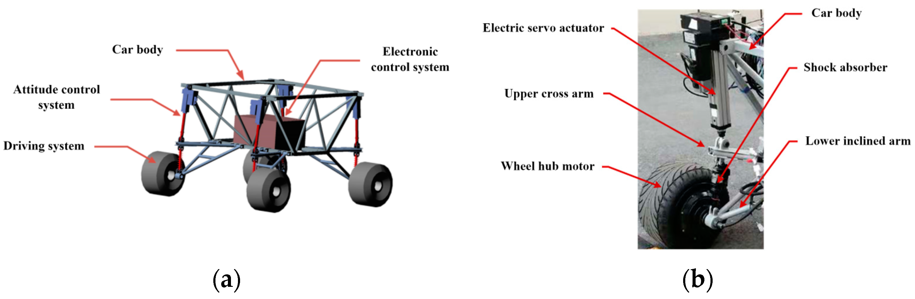
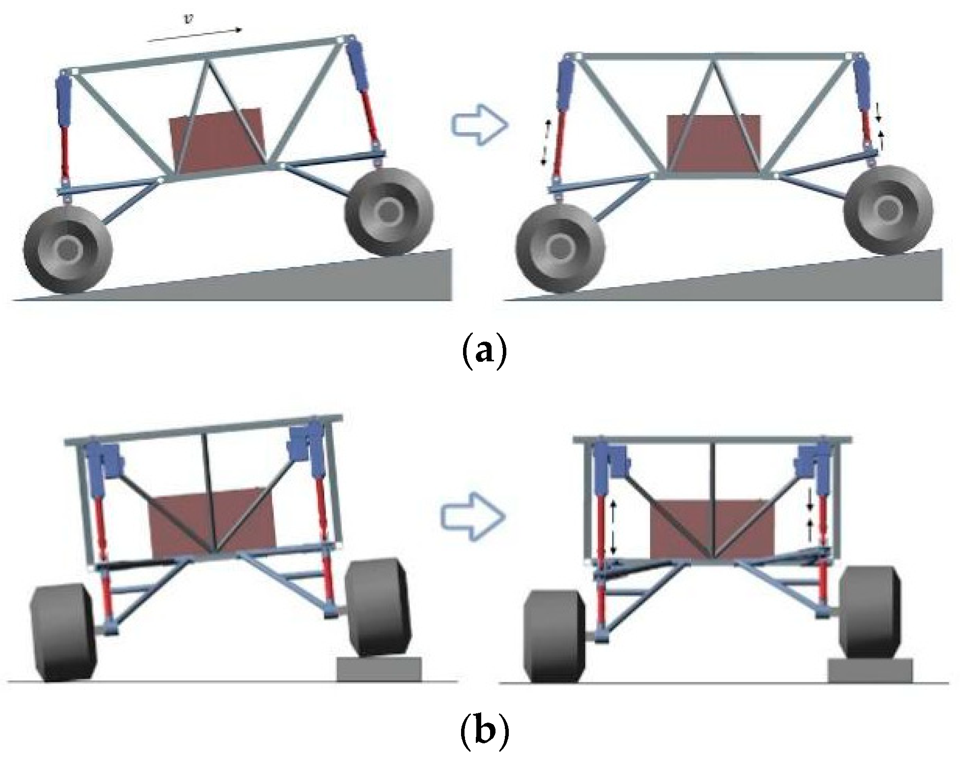
The attitude stability control of the vehicle is performed by four independent series active actuators, as shown in Figure 1b. The series active suspension combines an electric servo actuator, which is regarded as a displacement or velocity generator, with a passive air shock absorber. The internal control loop will involve speed and displacement feedback, and the control signal of the actuator will theoretically be the desired speed or displacement. As shown in Figure 7a, due to the height of the center of gravity and the effect of mass shift, the attitude of the car body is changed to squatting, when the vehicle is located on a slope. The proposed attitude stability control system will drive the front two actuators to shrink and the rear two actuators to extend for keeping the car body flat. In the same way, when the attitude is changed as tilting, the left actuator is extending and the right actuator is shrinking. The vehicle will always maintain a horizontal attitude, as shown in Figure 7b. When the car body swings in pitching and rolling motions on unstructured terrain, the attitude stability control system is used to adjust four actuators by giving speed or displacement signals in real time to achieve a steady body attitude so as to improve the stability and safety of the vehicle and loaded equipment.
In this paper, the model description and control constraint are analyzed by Model Predictive Control (MPC). MPC is very effective for control problems with low model accuracy and constraints. A system inevitably has nonlinear parts. For example, (4)–(7) in Section 2.1 simplify the nonlinearity of the vehicle and reduce the accuracy of the model. In addition, electric servo actuators also have constraints, such as speed and travel limits.
In each time interval, MPC calculates the first value of an open loop optimization problem within a finite time domain online in real-time, according to the measured value of the current system state by sensors [33]. At the next moment, the new open loop optimization problem is refreshed by the latest measured value. It realizes the purpose of real-time online optimization.
The design process of the model predictive controller includes three steps: prediction model, rolling optimization, and feedback correction. Firstly, the continuous system (17) is discretized [34] as:
A d = e A · T s
B d = 0 T s e A · T s d t · B
D d = 0 T s e A · T s d t · D
After discretization, the equation of state of the system is:
x k + 1 = A d x k + B d u k + D d w k y k = C d x k                                                                    
where k is a discrete time of the system, and A d , B d , D d , and C d are the coefficient matrix of the discrete system under T s sampling period. The detail of matrix, A, B, D is in Appendix A.
In this section, the MPC is solved by converting the cost function into the form of quadratic programming. The general form of quadratic programming [35] is as follows:
min Z T Q Z + C T Z
Then, it is as defined here:
X k = x k | k x k + 1 | k x k + N 1 | k x k + N | k
U k = u k | k u k + 1 | k u k + N 2 | k u k + N 1 | k
With the all-terrain vehicle as an attitude control object, control constraints of the electric servo actuator are as follows: maximum speed is the positive maximum speed that the actuator can achieve, minimum speed is the negative maximum speed, maximum displacement is half of the positive maximum travel, and minimum displacement is half of the negative maximum travel.
According to the system output, actuator input and weight factors, the performance index can be expressed in forms of the matrices and the vectors which represent the system states, disturbance inputs, and control forces as:
J = i = 0 N 1 y T k Q y k + u T k + i | k R u k + i | k y T k + N S y k + N
The symmetric positive definite constant matrix Q , R , and S are the weights of the output, input, and terminal error, respectively.
Therefore, the predicted values of system state x at time k can be expressed as:
x k | k = x k x k + 1 | k = A d x k + B d u k | k + D d w k , , x k + N | k = A d N x k + A d N 1 B d u k | k + , ,     + A d N 1 D d w k + , ,
According to (24)–(26) and (28), the system can be expressed in matrix form as follows:
X k = M x k + O U k + N W k
where
M = I A d A d N 1 A d N ,     O = 0 0 0 B d 0 0 A d B d B d 0 A d N 1 B d A d N 2 B d B d ,
N = 0 0 0 D d 0 0 A d D d D d 0 A d N 1 D d A d N 2 D d D d
According to (24)–(26), the cost function can be simplified to:
J = X T k C ¯ d T Q ¯ C ¯ d X k 2 E d T Q ¯ C ¯ d X k + E d T Q ¯ E d + U T k R ¯ U k
where
C ¯ d = C d C d C d , Q ¯ = Q Q S ,
E d = y d k y d k + 1 y d k + N , R ¯ = R R R
By substituting (29) into (30), the quadratic programming form of the cost function can be obtained through simplification as follows:
J = U T k C q U k + C e U k + C c
In (31), U k is solved based on the minimum of the quadratic programming form of the cost function. According to the above analysis and the system state, C q ,   C e , and C c can be calculated as follows:
C q = O T C ¯ d T Q ¯ C ¯ d O + R ¯ C e = 2 x T k M T C ¯ d T Q ¯ C ¯ d O + 2 W T k N T C ¯ d T Q ¯ C ¯ d O 2 E d T Q ¯ C ¯ d O C c = x T k M T C ¯ d T Q ¯ C ¯ d M x k + 2 C ¯ d N W k 2 E d + W T k N T C ¯ d T Q ¯ C ¯ d N W k 2 E d + E d T Q ¯ E d
The first item, as input to the current system, can be expressed as:
Δ u k = I     0   0 Δ U * k
At the end of this cycle, the optimal solution Δ u k 
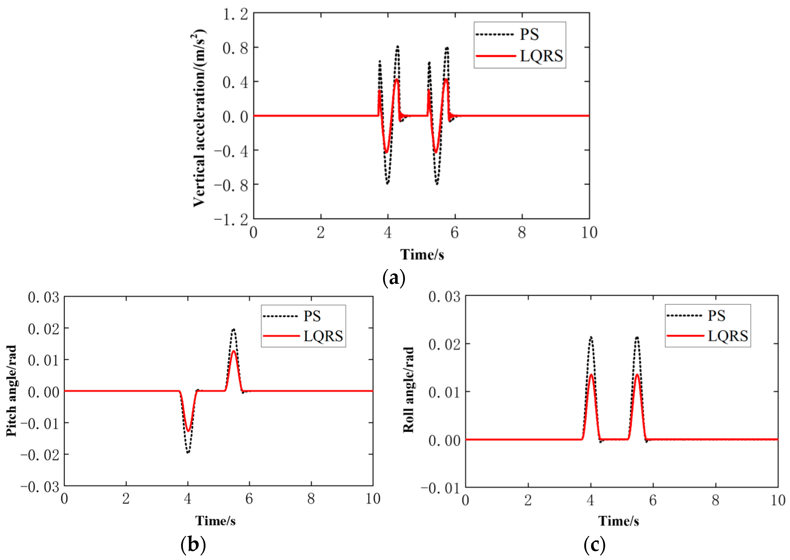
is obtained and applied to the system. The calculation process is repeated to the next time interval. In this way, the whole process of model prediction, rolling optimization, and feedback correction is completed. The attitude controller will drive the four series active suspension to achieve the reference attitude for keeping stability and improving ride comfort and safety. For further verifying the accuracy of vehicle modeling and performance of proposed controller, a LQR controller [36] is also derived by the above dynamic equations. The detail derivation of LQR method can be found in [3]. The corresponding programs can be found in the online data repository.

4. Simulation and Test

For achieving the controller design goals, the dynamic model is built depending on the main parameters presented in Table 1. Based on the model, an MPC controller for attitude stability control is derived. The performance of the proposed attitude controller is verified by simulations and real vehicle experiments as follows.

4.1. Simulation Analysis

Firstly, the vehicle is assumed to drive through three simulated road disturbances established in Section 2 at a speed of 1 m/sec in the simulation environment, such as a bumping road, sinusoidal road, or random road. The performance of the attitude model predictive control system (MPCS) is investigated by comparing vehicle rolling, pitching, and heaving motions with a passive suspension system (PS). Considering the model accuracy and the constraints of speed and displacement in the electric servo actuator, the performance indexes of the control system are shown in Table 2.
When the vehicle passes the bump roads at 1 m/s, Figure 8 shows the results of heaving acceleration, pitching, and rolling angle of the car body. All curves of MPCS are reduced compared with the passive system. The attitude stability of the car body is improved by the reduction of the above three values. The MPC controller is working well in bump roads.
In order to further test the performance of the proposed control system and the accuracy of the mathematical model, an optimal controller (LQRS) is also derived synchronously based on the same dynamic model. The simulation results are shown in Figure 9. By the comparison in Figure 8 and Figure 9, active attitude systems can significantly improve the stability and comfort of dealing with an instantaneous impact. As a controller which involved the model prediction part, MPC is similar to a controller embedded in a feed-forward incentive, so the response of MPCS is more positive. Considering the performance limitations of driving speed and displacement of the actuator and the constraint effect of the controller on them, the reduction of the heaving acceleration is not so significant. For further evaluating the performance of MPCS, the peak and RMS values are investigated, as shown in Table 3. In dealing with the bump road impact, the peak reduction ratios of heaving acceleration, pitching, and rolling angle of MPCS are 33.25%, 54.55%, and 56.74%, respectively. From another perspective, the RMS values of MPCS are also decreased by 28.95%, 47.62%, and 48.89% compared with PS.
When the vehicle passes the sinusoidal road at 1 m/s, Figure 10 shows the acceleration, pitching, and rolling angle of the car body. The heaving acceleration of MPCS is reduced to a lesser degree than other angular motions, but the control system is still working well. As shown in Table 4, the peak reduction ratios of MPCS are 10.6%, 49.45%, and 35.76%, respectively, dealing with the continuous sinusoidal road. The reduction ratios of RMS are 10.62%, 49.54%, and 50.63%, respectively. The results show that the proposed controller can improve ride comfort and attitude stability of the vehicle dealing with continuous sinusoidal road disturbance.
When the vehicle passes D-level random road disturbances at 1 m/s, the simulated results of MPCS in Figure 11 are closer to the ideal value. As shown in Table 5, the RMS of MPCS is decreased by 41.64%, 74.95%, and 73.61%, respectively. The controller also improves comfort and attitude stability dealing with the random road.
The average improvement effect of vehicle attitude under the above three kinds of road conditions is shown in Table 6. The analysis shows that the peak reduction ratio of pitching and rolling angle reaches 46.32% and 46.48%, and the corresponding average reduction ratio of RMS value reaches 48.74% and 50.4%. It indicates that the control effect of vehicle attitude is obvious. In addition, the heaving acceleration of the vehicle was reduced by more than 24.40%. It indicates that the ride comfort is still improved under the constraints of actuator performance and controller. In general, the MPC attitude controller mentioned in this paper can achieve significant performance improvement in attitude stability and comfort in the simulation environment.

4.2. Test Analysis

In order to further verify the effectiveness of the MPC controller, the test scheme designed in the above section is used to build a real vehicle control system composed of the host computer and Kvaser Light v2 to conduct real vehicle tests of attitude stability. Due to the limitations of the experimental conditions, such as the road length and experimental site, the real vehicle experiment adopts bump road disturbances as the terrain input. The parameter settings of the controller are consistent with those of the simulation. The sampling frequency is set as 100 Hz. Test results of the attitude control system are as follows.
Figure 12 shows the test results of the heaving acceleration, pitching, and rolling angle of the vehicle using an MPC controller. The heaving acceleration level of the sprung mass is reduced. The pitching and rolling angle are changed significantly, which can reduce the disadvantaged swing of the car body caused by road disturbances. However, it can also be observed that due to the action response delay of the actuator and a large amount of MPC control strategy calculation, the body attitude began to be actively changed after 0.3 s. Figure 13 shows the real vehicle control effect of an LQR controller. Compared with the results of MPCS, because the LQR controller does not consider excitation of the prediction part and the actuator itself has a delay problem, the responses of MPC system are more active, and the responses of LQR system seem to be more stable. Table 7 shows the specific data compared results of the attitude control system. The analysis shows that the peak reduction ratios of heaving acceleration, pitching, and rolling angle are 17.22%, 33.33%, and 37.24%, respectively, and the RMS values are decreased by 5.6%, 37.31%, and 34.18%. The above results verify the effectiveness of the proposed MPC controller and show that the MPC controller can maintain a good attitude control effect.
As shown in Figure 14, in comparison to the results, the improvement effect in the experiment is lower than the ones in the simulation environment. The difference is basically about 10%. Considering the difference between the linear model and real vehicle, actuator response time delay, and factors such as wear and tear, it makes sense for there to be a difference between the simulation and the real vehicle tests, but the improved trend is consistent. It fully explains the positive effect of the proposed attitude control system in improving vehicle attitude stability and ride comfort.

5. Conclusions

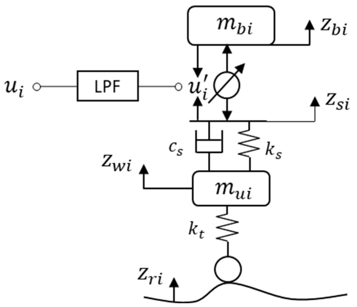
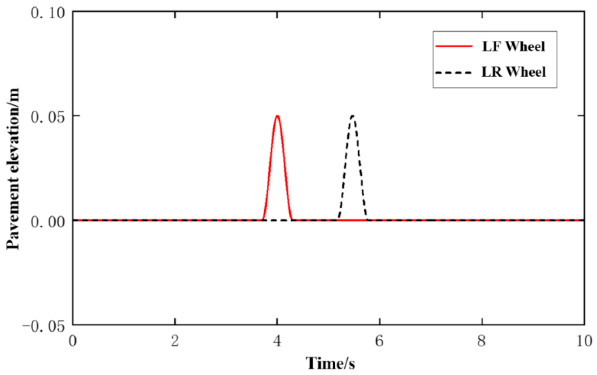
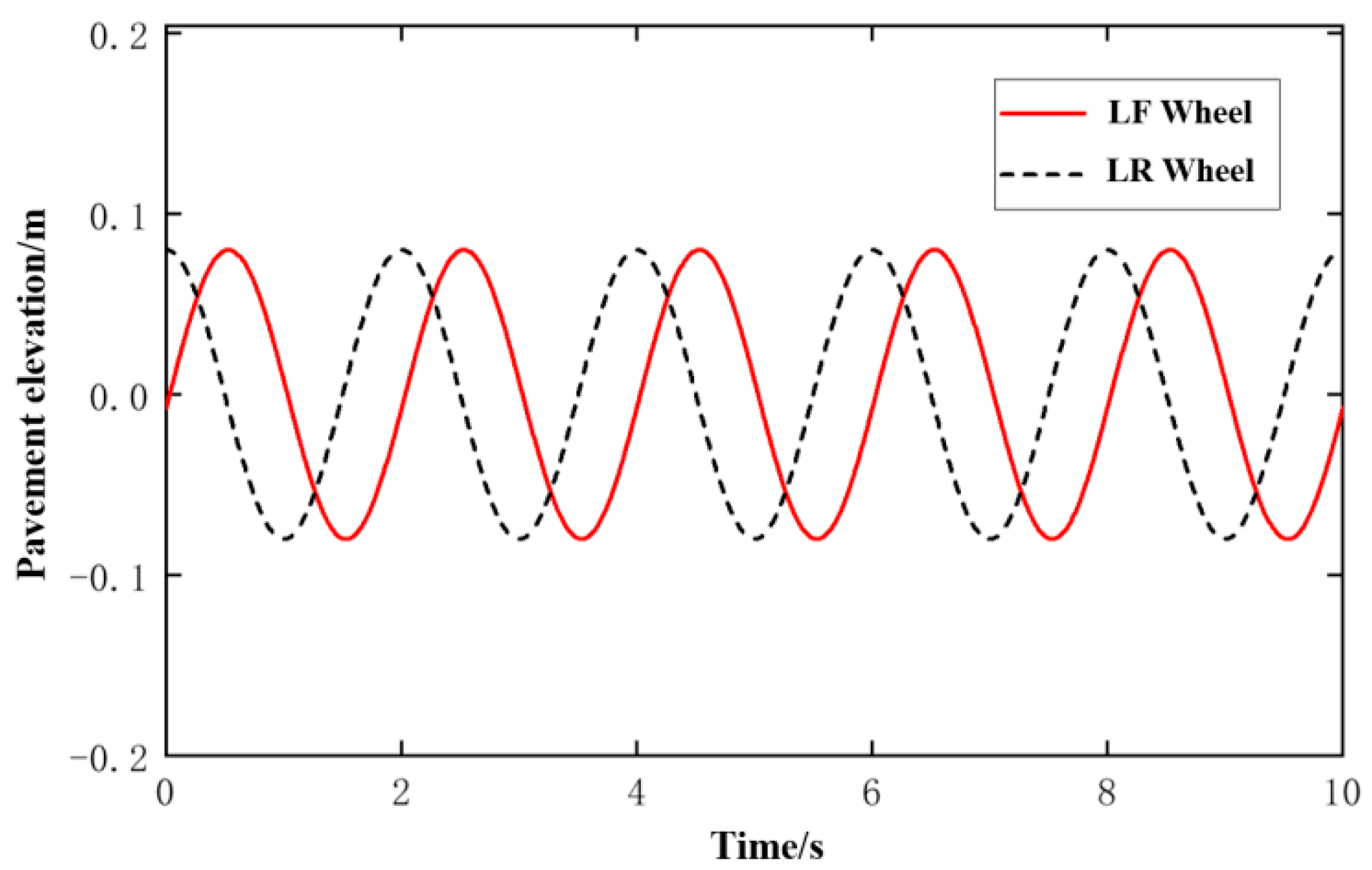
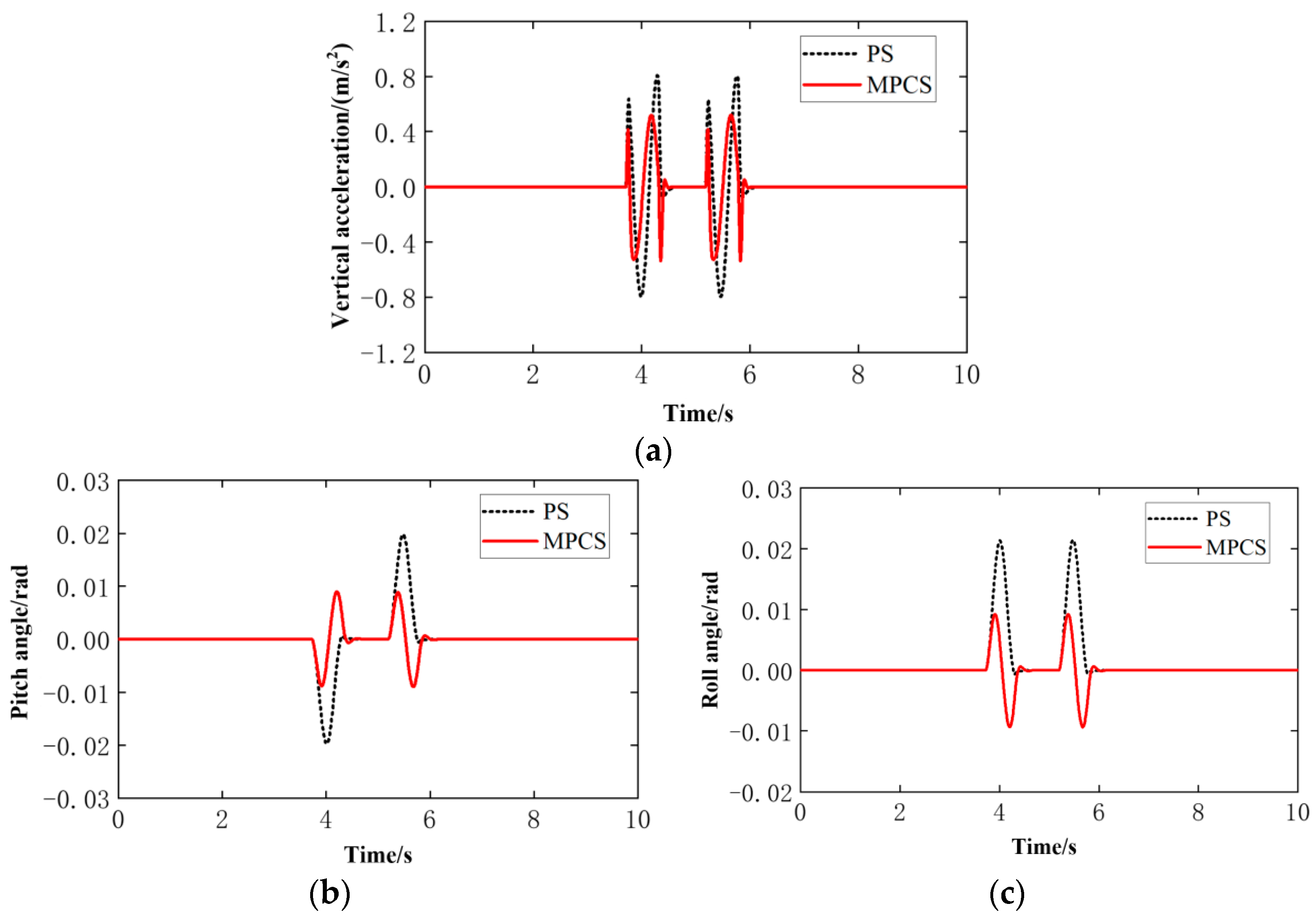
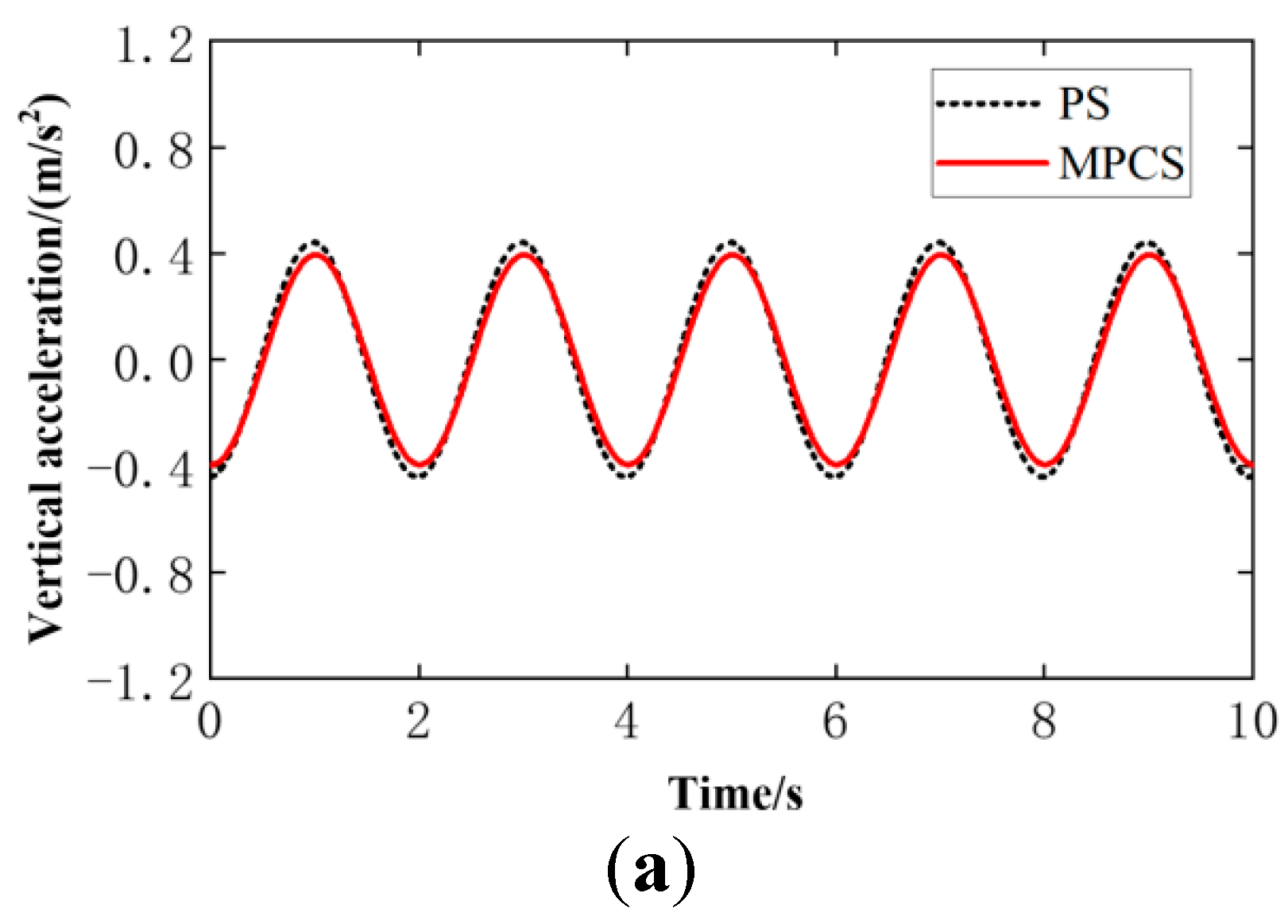
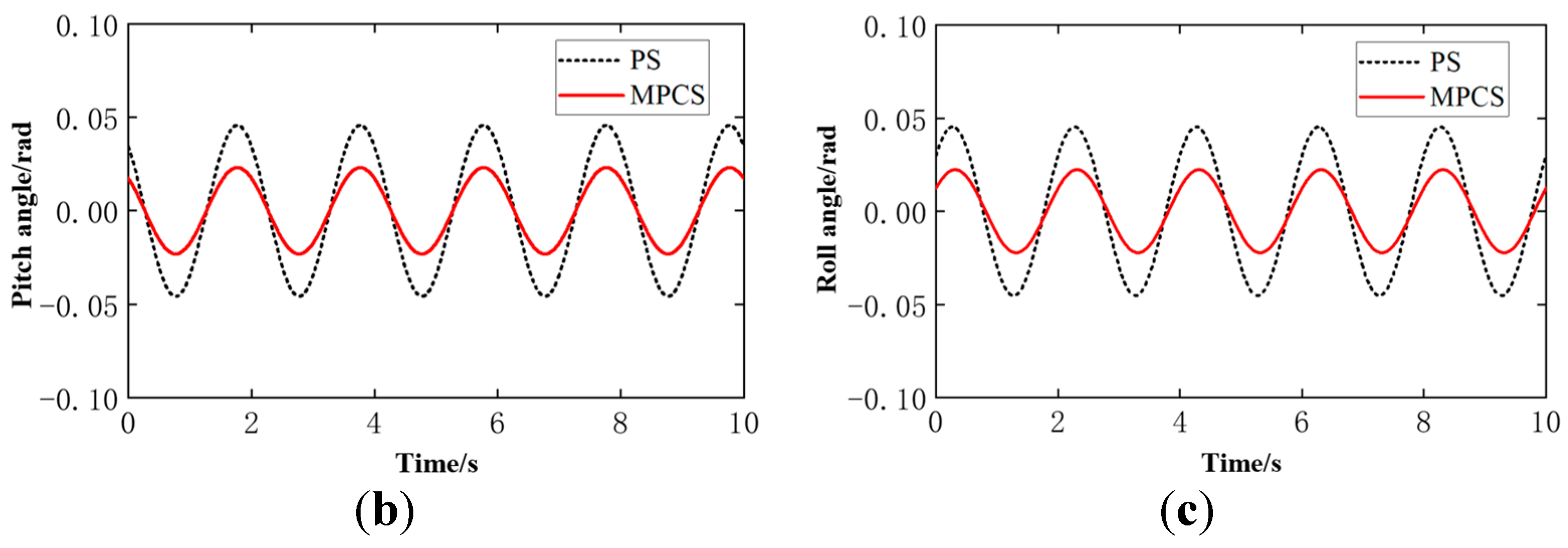
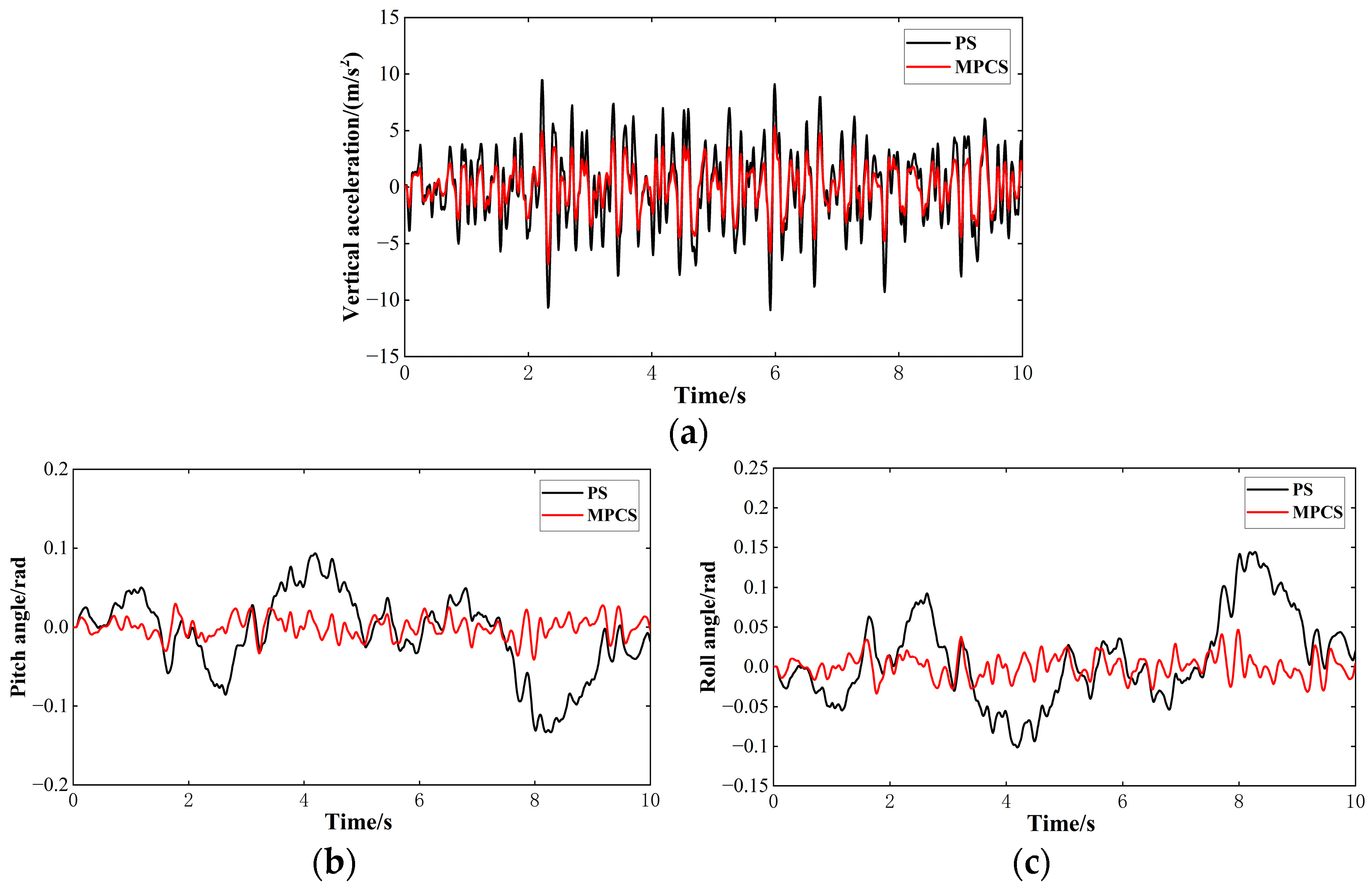
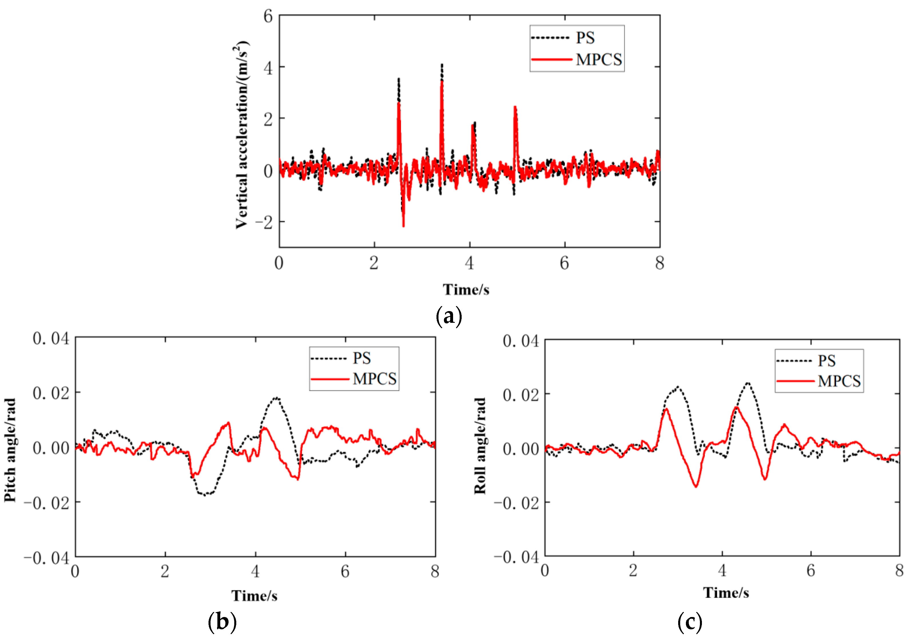
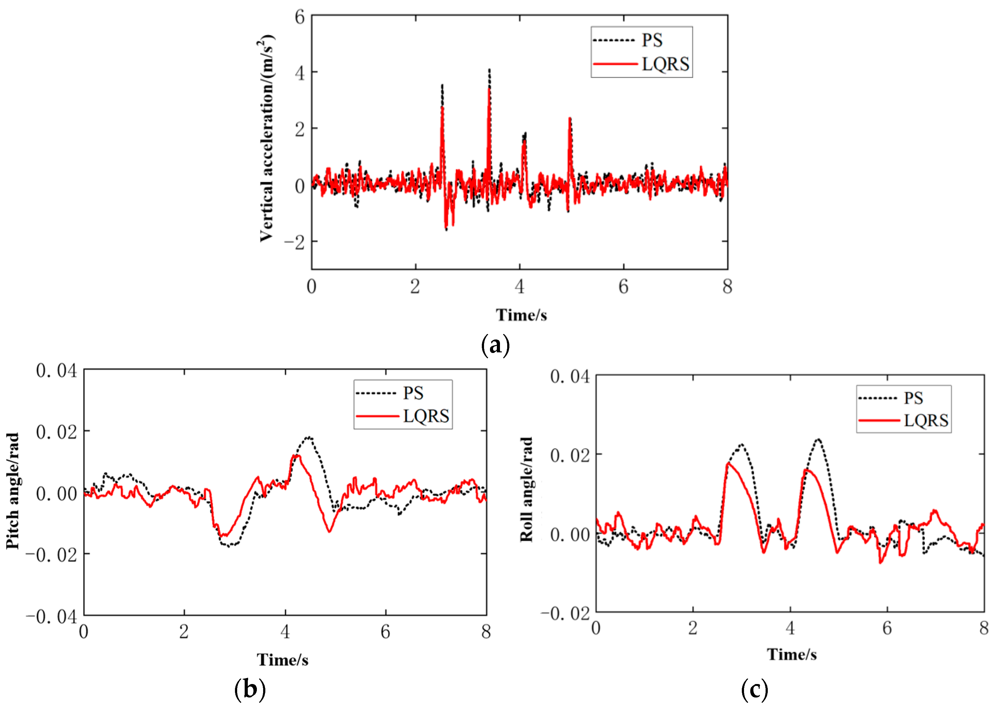
In order to improve the attitude stability and ride comfort by the series active suspensions in the case of unstructured terrain, this research builds a full car model for the innovative all-terrain vehicle and analyzes the kinematics and dynamics of each machine based on the series active suspensions. A second-order low-pass filter is introduced into the series active suspension for solving the difficulty of speed control modeling of the electric servo actuator. The transient, steady, and random response characteristics of the MPC attitude control system are verified, respectively, under various road disturbances.
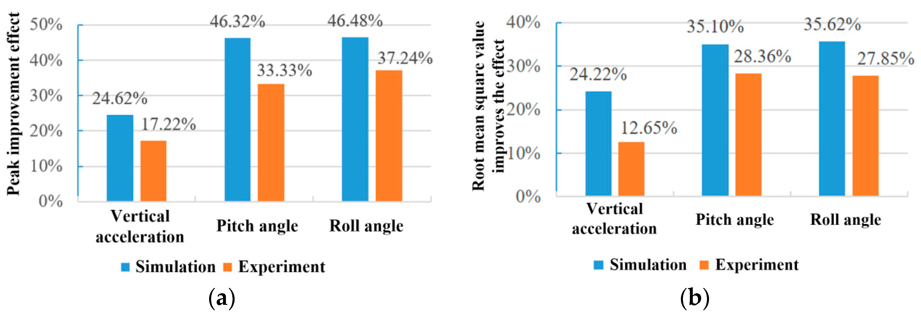
Considering the bump, sinusoidal, and random road disturbances, the attitude controller designed in this paper reduces unexpected angular motions and acceleration of car body by more than 46% and 24% in the simulation environment while meeting the actuator constraints. The real tests show that unexpected angular motions and acceleration of car body are also reduced by more than 33% and 12%. Finally, the attitude controller on the self-designed ATV can obviously reduce the pitching, rolling angle, and heaving acceleration of the car body on different road conditions so as to achieve design goals and improve both attitude stability and ride comfort of the vehicle.

Author Contributions

Conceptualization, W.J. and L.W.; methodology, all authors; software, L.W.; validation, all authors; investigation, W.Z., W.J. and L.W.; resources, L.W. and F.M.; writing—original draft preparation, W.J.; writing—review and editing, W.Z., L.W. and W.J.; supervision, F.M.; project administration, F.M.; funding acquisition, W.J. All authors have read and agreed to the published version of the manuscript.

Funding

This research got support from National Social Science Fund of China (17CGL006).

Institutional Review Board Statement

The study was approved by the Institutional Review Board of Jilin University of Finance and Economics, China.

Data Availability Statement

The program supporting the conclusions of this article will be made available by the authors, without undue reservation. Enquiries can be directed to the corresponding author.

Acknowledgments

We thank Guangjian Xu for help with the mechanical design as a former graduate student at Jilin University. We also acknowledge the experiment support from Changsha Automobile Research Institute of Jilin University.

Conflicts of Interest

The authors declare no conflict of interest.

Appendix A

The MATLAB calculation program of matrix a, b, c, and d is shown below:
  • function [A,B,C,D]=system_state_22x(~)
  • syms mb muf mur ktf ktr a b Bf Br Cs1 Cs2 Cs3 Cs4 ks1 ks2 ks3 ks4 dru cfu...
 x1 x2 x3 x4 x5 x6 x7 x8 x9 x10 x11 x12 x13 x14 x15 x16 x17 x18 x19 x20 x21 x22...
 w1 w2 w3 w4 u1 u2 u3 u4 Ip Ir...
 fs1 fs2 fs3 fs4...%force of acuator
  • zb1 = x4 − a * x5 + 1/2 * Bf * x6;
  • zb2 = x4 − a * x5 − 1/2 * Bf * x6;
  • zb3 = x4 + b * x5 + 1/2 * Br * x6;
  • zb4 = x4+ b * x5 − 1/2 * Br * x6;
  • dzb1 = x1 − a * x2 + 1/2 * Bf * x3;
  • dzb2 = x1 − a * x2 − 1/2 * Bf * x3;
  • dzb3 = x1 + b * x2 + 1/2 * Br * x3;
  • dzb4 = x1 + b * x2 − 1/2 * Br * x3;
  • fs1 = Cs1 * (x7 − dzb1 − x15) + ks1 * (x11 − zb1 − x19); %u = zb − zs
  • fs2 = Cs2 * (x8 − dzb2 − x16) + ks2 * (x12 − zb2 − x20);
  • fs3 = Cs3 * (x9 − dzb3 − x17) + ks3 * (x13 − zb3 − x21);
  • fs4 = Cs4 * (x10 − dzb4 − x18) + ks4 * (x14 − zb4 − x22);
  • f1 = 1/mb * (fs1 + fs2 + fs3 + fs4); %ddzb
  • f2 = ((fs3 + fs4) * b − (fs1 + fs2) * a)/Ip; %ddtheta
  • f3 = ((fs1 − fs2) * 1/2 * Bf + (fs3 − fs4) * 1/2 * Br)/Ir; %ddfai
  • f4 = x1; f5 = x2; f6 = x3;
  • f7 = 1/muf * (ktf * (w1 − x11) − fs1);
  • f8 = 1/muf * (ktf * (w2 − x12) − fs2);
  • f9 = 1/mur * (ktr * (w3 − x13) − fs3);
  • f10 = 1/mur * (ktr * (w4 − x14) − fs4);
  • f11 = x7;
  • f12 = x8;
  • f13 = x9;
  • f14 = x10;
  • f15 = −2 * dru * cfu * x15 − cfu * cfu * x19 + cfu * cfu * u1;
  • f16 = −2 * dru * cfu * x16 − cfu * cfu * x20 + cfu * cfu * u2;
  • f17 = −2 * dru * cfu * x17 − cfu * cfu * x21 + cfu * cfu * u3;
  • f18 = −2 * dru * cfu * x18 − cfu * cfu * x22 + cfu * cfu * u4;
  • f19 = x15;
  • f20 = x16;
  • f21 = x17;
  • f22 = x18;
  • y1 = f1;
  • y2 = f2;
  • y3 = f3;
  • y4 = x4;
  • y5 = x5;
  • y6 = x6;
  • y7 = −1 * (x11 − zb1 − x19);
  • y8 = −1 * (x12 − zb2 − x20);
  • y9 = −1 * (x13 − zb3 − x21);
  • y10 = −1 * (x14 − zb4 − x22);
  • x = [x1 x2 x3 x4 x5 x6 x7 x8 x9 x10 x11 x12 x13 x14 x15 x16 x17 x18 x19 x20 x21 x22];
  • u = [u1 u2 u3 u4];
  • w = [w1 w2 w3 w4];
  • X = [f1;f2;f3;f4;f5;f6;f7;f8;f9;f10;f11;f12;f13;f14;f15;f16;f17;f18;f19;f20;f21;f22];
  • Y = [y1;y4;y5;y6;y7;y8;y9;y10;x15;x16;x17;x18;x19;x20;x21;x22];
  • A = jacobian (X,x);
  • B = jacobian (X,u);
  • C = jacobian (Y,x);
  • D = jacobian (X,w);

References

  1. Pan, H.; Sun, W.; Gao, H.; Hayat, T.; Alsaadi, F. Constrained robust adaptive control for vehicle active suspension systems. Int. J. Veh. Des. 2015, 68, 5–21. [Google Scholar] [CrossRef]
  2. Zhou, Y.; Wang, R.; Ding, R.; Shi, D.; Ye, Q. Investigation on hierarchical control for driving stability and safety of intelligent HEV during car-following and lane-change process. Sci. China Technol. Sci. 2021, 65, 1–24. [Google Scholar] [CrossRef]
  3. Youn, I.; Wu, L.; Youn, E.; Tomizuka, M. Attitude motion control of the active suspension system with tracking controller. Int. J. Automot. Technol. 2015, 16, 593–601. [Google Scholar] [CrossRef]
  4. Wu, L.; Khan, A.M.; Youn, E. Attitude motion control of vehicle including the active passenger seat system. Int. J. Vehicle Des. 2019, 78, 131–160. [Google Scholar]
  5. Wu, L.; Ejaz, A.; Khan, A.M.; Youn, I. Integration of active tilting control and full-wheel steering control system on vehicle lateral performance. Int. J. Automot. Technol. 2021, 22, 979–992. [Google Scholar]
  6. Elmadany, M.M.; Qarmoush, A.O. Dynamic Analysis of a Slow-active Suspension System Based on a Full Car Model. J. Vib. Control 2011, 17, 39–53. [Google Scholar] [CrossRef]
  7. Horton, D.N.L.; Crolla, D.A. Theoretical Analysis of a Semi Active Suspension Fitted to an Off-Road Vehicle. Veh. Syst. Dyn. 2007, 15, 351–372. [Google Scholar] [CrossRef]
  8. Gu, C.; Yin, J.; Chen, X. Robust control and optimization of a rockerpushrod electromagnetic active suspension. Automot. Eng. 2018, 40, 34–40. [Google Scholar]
  9. Gao, Y.; Wang, D.; Wei, W.; Yu, Q.; Liu, X.; Wei, Y. Constrained Predictive Tracking Control for Unmanned Hexapod Robot with Tripod Gait. Drones 2022, 6, 246. [Google Scholar] [CrossRef]
  10. Chen, G.; Lu, Y.; Yang, X.; Hu, H. Reinforcement learning control for the swimming motions of a beaver-like, single-legged robot based on biological inspiration. Robot. Auton. Syst. 2022, 154, 104116. [Google Scholar] [CrossRef]
  11. Garcia, E.; Arevalo, J.; Muñoz, G.; Gonzalez-De-Santos, P. Combining series elastic actuation and magneto-rheological damping for the control of agile locomotion. Robot. Auton. Syst. 2011, 59, 827–839. [Google Scholar] [CrossRef]
  12. He, G.; Geng, Z. Dynamics synthesis and control for a hopping robot with articulated leg. Mech. Mach. Theory 2011, 46, 1669–1688. [Google Scholar] [CrossRef]
  13. Wilcox, B.H.; Litwin, T.; Biesiadecki, J.; Matthews, J.; Heverly, M.; Morrison, J.; Townsend, J.; Ahmad, N.; Sirota, A.; Cooper, B. Athlete: A cargo handling and manipulation robot for the moon. J. Field Robot. 2007, 24, 421–434. [Google Scholar] [CrossRef]
  14. Kaur, S.; Bawa, G. Learning Robotic Skills through Reinforcement Learning. In Proceedings of the 2022 3rd International Conference on Electronics and Sustainable Communication Systems (ICESC), Coimbatore, India, 17–19 August 2022. [Google Scholar]
  15. Chen, G.; Yang, X.; Xu, Y.; Lu, Y.; Hu, H. Neural network-based motion modeling and control of water-actuated soft robotic fish. Smart Mater. Struct. 2022, 32, 015004. [Google Scholar] [CrossRef]
  16. Konieczny, J.; Kowal, J.; Raczka, W.; Sibielak, M. Bench Tests of Slow and Full Active Suspensions in Terms of Energy Consumption. J. Low Freq. Noise Vib. Act. Control 2013, 32, 81–98. [Google Scholar] [CrossRef]
  17. Van Der Westhuizen, S.F.; Els, P.S. Slow active suspension control for rollover prevention. J. Terramech. 2013, 50, 29–36. [Google Scholar] [CrossRef]
  18. Ni, L.; Ma, F.; Wu, L. Posture Control of a Four-Wheel-Legged Robot With a Suspension System. IEEE Access 2020, 8, 152790–152804. [Google Scholar] [CrossRef]
  19. Ni, L.; Ma, F.; Ge, L.; Wu, L. Design and Posture Control of a Wheel-Legged Robot With Actively Passively Transformable Suspension System. J. Mech. Robot. 2021, 13, 011014. [Google Scholar] [CrossRef]
  20. Erik, E.; Georg, B.; Nathan, M. Analysis of the influence of suspension actuator limitations on ride comfort in passenger cars using model predictive control. Actuators 2020, 9, 77. [Google Scholar]
  21. Guan, H.; Kim, K.; Wang, B. Comprehensive path and attitude control of articulated vehicles for varying vehicle conditions. Int. J. Heavy Veh. Syst. 2017, 24, 65–95. [Google Scholar] [CrossRef]
  22. Zhao, H.; Lu, X.; Chen, H.; Liu, Q.; Gao, B. Coordinated Attitude Control of Longitudinal, Lateral and Vertical Tyre Forces for Electric Vehicles Based on Model Predictive Control. IEEE Trans. Veh. Technol. 2022, 71, 2550–2559. [Google Scholar] [CrossRef]
  23. Xia, G.; Li, J.; Tang, X.; Zhang, Y.; Hu, J. Anti-rollover of the counterbalanced forklift truck based on model predictive control. J. Mech. Sci. Technol. 2021, 35, 1909–1921. [Google Scholar] [CrossRef]
  24. Chen, W.; Li, J.; Tang, X.; Xia, G.; Zhang, Y. Reaserch on anti-rollover model predictive control of counterbalanced forklift trucks. China Mech. Eng. 2021, 32, 987. [Google Scholar]
  25. Chang, D.E.; Phogat, K.S.; Choi, J. Model Predictive Tracking Control for Invariant Systems on Matrix Lie Groups via Stable Embedding Into Euclidean Spaces. IEEE Trans. Autom. Control 2020, 65, 3191–3198. [Google Scholar] [CrossRef]
  26. Alejandro, P.; Antonio, F.; Francisco, C.F.; Luis, B.C.; Camilo, L. An ARX model-based predictive control of a semi-active vehicle suspension to improve passenger comfort and road-holding. Actuators 2021, 10, 47. [Google Scholar]
  27. Jimoh, O.P.; Sakhile, M.S.N.; Lindokuhle, J.M. Model predictive control of half-car active suspension systems using particle swarm optimisation. IFAC PapersOnLine 2020, 53, 14438–14443. [Google Scholar]
  28. Johan, T.; Aldo, S.; Patrick, G.; Saber, F.; Marco, R.; Michal, K.; Miguel, D. Regionless explicit model predictive control of active suspension systems with preview. IEEE Trans. Ind. Electron. 2020, 67, 4877–4888. [Google Scholar]
  29. Moradi, S.M.; Ahmad, A.; Mehdi, M. An offline LMI-based robust model predictive control of vehicle active suspension system with parameter uncertainty. Trans. Inst. Meas. Control 2019, 41, 1699–1711. [Google Scholar] [CrossRef]
  30. GB/T 4970-2009; Test Method for Vehicle Ride Comfort. Standards Press of China: Beijing, China, 1985.
  31. Tian, W.; Dou, J.; Xu, X. Modelling and characteristics of hybrid coupling hydro-pneumatic suspension for a seven-axle vehicle. Proc. Inst. Mech. Eng. Part D J. Automob. Eng. 2021, 35, 1892–1901. [Google Scholar]
  32. Shi, X.; Jiang, X.; Zhao, J. Seven degrees of freedom vehicle response characteristic under four wheel random pavement excitation. Sci. Technol. Eng. 2018, 18, 71–78. [Google Scholar]
  33. Ni, T.; Li, W.; Zhang, H.; Yang, H.; Kong, Z. Pose Prediction of Autonomous Full Tracked Vehicle Based on 3D Sensor. Sensors 2019, 19, 5120. [Google Scholar] [CrossRef] [PubMed]
  34. Ogata, K. State Space Analysis of Control Systems; Prentice-Hall: Englewood Cliffs, NJ, USA, 1967. [Google Scholar]
  35. Bartlett, R.A.; Biegler, L.T.; Backstrom, J.; Gopal, V. Quadratic programming algorithms for large-scale model predictive control. J. Process. Control 2002, 12, 775–795. [Google Scholar] [CrossRef]
  36. Tchamna, R.; Lee, M.; Youn, I.; Maxim, V.; Židek, K.; Kelemenová, T. Management of linear quadratic regulator optimal control with full-vehicle control case study. Int. J. Adv. Robot. Syst. 2016, 13, 1729881416667610. [Google Scholar] [CrossRef] [Green Version]
Figure 1. All-terrain vehicle structure: (a) All-terrain vehicle 3D model; (b) All-terrain vehicle real model.
Actuators 12 00067 g001
Figure 2. A simplified All-terrain vehicle model.
Actuators 12 00067 g002
Figure 3. A series active suspension with a second-order low-pass filter.
Actuators 12 00067 g003
Figure 4. Bump road disturbances on the left front and rear wheels.
Actuators 12 00067 g004
Figure 5. Sinusoidal road disturbances on the Left front and rear wheels.
Actuators 12 00067 g005
Figure 6. D-class road disturbances on left front and rear wheels.
Actuators 12 00067 g006
Figure 7. Ideal posture of ATV attitude control: (a) Pitching control process; (b) Rolling control process.
Actuators 12 00067 g007
Figure 8. Simulation results of MPC attitude control for bump roads: (a) Heaving acceleration of car body; (b) Pitching angle of car body; (c) Rolling angle of car body.
Actuators 12 00067 g008
Figure 9. Simulation results of LQR attitude control for bump roads: (a) Heaving acceleration of car body; (b) Pitching angle of car body; (c) Rolling angle of car body.
Actuators 12 00067 g009
Figure 10. Simulation results of attitude control on a sinusoidal road: (a) Heaving acceleration of car body; (b) Pitching angle of car body; (c) Rolling angle of car body.
Actuators 12 00067 g010aActuators 12 00067 g010b
Figure 11. Simulation results of random road attitude control: (a) Heaving acceleration of car body; (b) Pitching angle of car body; (c) Rolling angle of car body.
Actuators 12 00067 g011
Figure 12. Experimental results of MPCS under the bump road disturbances: (a) Heaving acceleration of car body; (b) Pitching angle of car body; (c) Rolling angle of car body.
Actuators 12 00067 g012
Figure 13. Experimental results of LQR under bump road disturbances: (a) Heaving acceleration of car body; (b) Pitching angle of car body; (c) Rolling angle of car body.
Actuators 12 00067 g013
Figure 14. The comparison between simulation and experimental results under bump road disturbances: (a) Peak value contrast; (b)RMS value.
Actuators 12 00067 g014
Table 1. Parameters of the Vehicle.
ParameterValue
Wheelbase/mm1300
Wheel track/mm1200
Ground clearance/mm473
Tire radius/mm190
Body quality/kg150
Wheel quality/kg10
Pitch moment of inertia/kg m22029
Roll moment of inertia /kg m216.2
Table 2. Performance Index of the Control System.
ParameterValue
Sampling time T s 0.01 s
Predict time domain p 20
Control time domain m5
Maximum speed of the actuator u ˙ max 0.125 m/s
Minimum speed of the actuator u ˙ m i n 0.125 m/s
Maximum upward travel of the actuator u m a x 0.1 m
Maximum upward stroke of the actuator u m i n 0.1 m
Weighting coefficient of heaving acceleration of vehicle body Γ y , i z ˙ b 0
Weighting coefficient of heaving body displacement Γ y , i z 39.5
Weighting coefficient of pitching angle Γ y , i θ 1.8
Weighting coefficient of the rolling angle Γ y , i φ 1.8
Weighting coefficient of the control quantity Γ u , i u i 0.1
Table 3. Simulation Results of Peak Value and RMS Value of Attitude Stability Control Under Bump Road Disturbances.
Performance IndicatorsPSMPCSReduction Ratio
Peak valueHeaving acc./(m/s2)0.80630.538233.25%
Pitch angle/rad0.01980.009054.55%
Roll angle/rad0.02150.009356.74%
RMS valueHeaving acc./(m/s2)0.19450.138228.95%
Pitch angle/rad0.00420.002247.62%
Roll angle/rad0.00450.002348.89%
Table 4. Simulation Results of Peak Value and RMS Value of Attitude Stability Control Under Sinusoidal Road Disturbances.
Performance IndicatorsPSMPCSReduction Ratio
Peak valueHeaving acc./(m/s2)0.44170.394910.60%
Pitch angle/rad0.04570.023149.45%
Roll angle/rad0.04530.022335.76%
RMS valueHeaving acc./(m/s2)0.31250.279310.62%
Pitch angle/rad0.03230.016349.54%
Roll angle/rad0.03200.015850.63%
Table 5. Simulation results of Peak Value and RMS Value of attitude stability control under Random Road Disturbances.
Performance IndicatorsPSMPCSReduction Ratio
Peak valueHeaving acc./(m/s2)10.87756.791337.57%
Pitch angle/rad0.13320.041169.14%
Roll angle/rad0.14420.046667.68%
RMS valueHeaving acc./(m/s2)3.32281.939141.64%
Pitch angle/rad0.05150.012974.95%
Roll angle/rad0.05570.014773.61%
Table 6. Simulation Results of Peak Value and RMS Value of MPC Attitude Control Under Three Kinds of Road Surfaces.
Performance IndicatorsAverage Peak Reduction RatioAverage Reduction Ratio of RMS
Heaving acceleration of the vehicle/(m/s2)24.62%24.40%
Pitch angle/rad46.32%48.74%
Roll angle/rad46.48%50.40%
Table 7. Experimental Results of Peak Value and RMS Value Under Bump Road Disturbances.
Performance IndicatorsPSMPCSReduction Ratio
Peak valueHeaving acc./(m/s2)4.12583.415317.22%
Pitch angle/rad0.01800.012033.33%
Roll angle/rad0.02390.015037.24%
RMS valueHeaving acc./(m/s2)0.47110.44475.60%
Pitch angle/rad0.00670.004237.31%
Roll angle/rad0.00790.005234.18%
Disclaimer/Publisher’s Note: The statements, opinions and data contained in all publications are solely those of the individual author(s) and contributor(s) and not of MDPI and/or the editor(s). MDPI and/or the editor(s) disclaim responsibility for any injury to people or property resulting from any ideas, methods, instructions or products referred to in the content.

