1. Introduction
With the advent of Industry 4.0, robotic arms are used in a variety of industries, such as medicine, industrial production, and aerospace [
1,
2,
3]. At this stage, with the research and application of robotic arms, the efficiency of industrial production has been greatly improved [
4,
5,
6]. Motion planning is a crucial area of research in the industrial robotic arm field. Over the years, as more industrial robotic arm applications have surfaced, the demand for motion planning of industrial robotic arms has increased to accommodate varied scenario requirements. Among them, the assembly environment is one of several application scenarios, as it involves multiple assembly target points and necessitates that the industrial robotic arm avoids colliding with obstacles in the scene between those target points.
In the field of three-dimensional motion planning for robotic arms, the sampling-based graph search algorithm has been shown to be effective in high-dimensional and complex environments compared to other algorithms [
7]. The method includes the rapidly exploring random tree (RRT) [
8] and the probabilistic roadmap method (PRM) [
9]. Compared to the PRM algorithm, the RRT algorithm does not require the construction of a path map. It can effectively solve the path planning problem of a robotic arm in high dimensions and possesses strong exploration capabilities and a high probability of completeness in high-dimensional space. However, the algorithm’s randomness can result in problems of blindness and slow search speeds, as well as insufficient exploration abilities for complex environments.
In response to the limitations of the RRT algorithm, researchers have proposed various solutions. For instance, some have incorporated the greedy algorithm into the RRT algorithm to achieve the RRT-connect dual-tree algorithm. RRT-connect generates two trees from the start and end points, respectively, which speeds up the path searching speed, but in essence, it is still a tree derived from the RRT algorithm, which does not guarantee the optimality of the path and the cost of the tree’s growth [
10]. Wang et al. proposed a variable step size RRT method, which speeds up the convergence of the RRT algorithm but cannot control the step size of their tree in the workspace [
11]. Therefore, Karaman et al., in order to address the poor asymptotic optimality of RRT, added ChooseParent and Rewire optimization modules to optimize the path length by re-selecting the parent node and rewiring. As long as the search time is sufficient, a near-optimal path can be obtained. However, the problem of low search efficiency persists [
12]. However, it is undeniable that RRT* is an important milestone in the study of the RRT family of algorithms. The RRT*Smart algorithm adds smart algorithms to the sampling process. The addition of smart algorithms speeds up the convergence of the RRT* algorithm and reduces the path cost, but it also leads to a reduction in the probability of searching for different configurations due to the dependence on the quality of the initial solution, violating the uniform sampling assumption of RRT* [
13]. To ensure a better sampling space for generating RRT*, Gammell et al. proposed the Informed-RRT* algorithm, which uses RRT* to solve the initial solution and generates an elliptic state-space region determined by the initial point, the target point, and the length of the path. This algorithm speeds up convergence to the optimal solution as the optimization range shrinks, but it still relies on undirected exploration and struggles to handle complex environments [
14]. A fusion algorithm combining potential field and particle swarm optimization (PSO) can predict dynamic obstacles and obtain satisfactory paths [
15].
Khatib proposed the artificial potential field (APF) method in 1986 for path planning. Assuming a joint force comprising the obstacle’s repulsive force and the goal point’s gravitational force, the algorithm guides the robot through the obstacle. However, the method is prone to local minima or oscillations, and there may be instances where the robot cannot reach the goal point [
16]. To enhance search efficiency, Qureshi et al. combined RRT* with the artificial potential field (APF) method in an intelligence-based path planning algorithm, resulting in the P-RRT* algorithm. With the addition of APF, the growth of the tree has directionality, enabling faster convergence speed compared to the RRT* algorithm. However, the issue of the artificial field potential method falling into local minima remains unresolved [
17].
In addition, Jeong proposed Quick RRT*, which uses trigonometric inequalities to improve the ChooseParent and Rewire procedures, allowing Quick RRT* to have a faster convergence rate compared to RRT* [
18].PQ-RRT* combines P-RRT * with Quick-RRT*, allowing the algorithm to produce better initial solutions, which can quickly converge to a relatively optimal solution [
19]. Since PQ-RRT* only considers static path planning and does not take path planning in dynamic environments into account, it has limitations. Therefore, Yu et al. improved New Potential Quick-RRT* (NPQ-RRT*) for UAV applications [
20]. After completing the path planning, in order to ensure the quality of the path, it is also necessary to optimize the planning path with smoothing [
21,
22]. Since the paths are optimized in a two-dimensional environment, they have high-dimensional limitations. Guo et al. proposed an optimal B-spline curve to produce smoother and shorter paths, which is particularly suitable for closed paths, and applied to robotic arms [
23].
On the basis of the above study, for the problems of low search efficiency and slow convergence speed of RRT series algorithms in robotic arm motion planning, the Improved Potential Quick-RRT* connect (IPQ-RRT* connect) algorithm adds a node-greedy bidirectional scaling strategy on the basis of the PQ-RRT* algorithm. This strategy uses a bidirectional algorithm to scan the obstacles on the map and set an obstacle detection range in the process of random tree sampling, adopting different node sampling methods according to different detection results to realize dynamically coordinated double random tree growth. In addition, the hierarchical wraparound box method is used to ensure the effectiveness of collision detection of the assembly robotic arm in the assembly process. Finally, the Bezier curve method is used to smooth the trajectory curve to realize the motion planning of the assembly robotic arm.
2. Problem Description
During the assembly process of an assembly robotic arm, it needs to pass through several target points to accomplish different tasks. The following problems need to be solved during the operation of the robotic arm. First of all, a series of target points, as well as task sequencing, should be set up, and the running path of the robotic arm should arrive at these target points in sequence according to the task requirements. In addition, the robotic arm should not collide with obstacles during the running process, and it should keep running smoothly.
Throughout this paper, assume that denotes a set of real numbers, denotes a set of natural numbers, and denotes a vector space.
Then, assume that is a three-dimensional bitmap space, , . Assuming that is the obstacle area, the accessible space is denoted as . and are the initial configuration and target area. Let the continuous function , A continuous function is called a collision-free path if it is collision-free in a three-dimensional bitmap space.
Problem 1 (Task Guidance). Tasks need to be sequenced during the assembly process to guide the end-effector of the assembly industrial robotic arm through these target points in order to complete the assembly task.
Problem 2 (Feasible Path Planning). Set a triplet , find a feasible path in three-dimensional bitmap space, unify all feasible paths into a set , and report success if a feasible path exists in three-dimensional space , otherwise, report failure of path search.
Problem 3 (Optimal Path Planning). Set up a triplet and a cost function to compute a feasible path , .
Problem 4 (Fast Path Planning). Find the optimal path solution in the shortest time in the same three-dimensional bitmap space.
Problem 5 (Jitter Reduction). While satisfying the above issues, the smoothness of the robotic arm path needs to be satisfied to minimize the jitter of the robotic arm.
3. Methodology
In this paper, we first analyzed the overall assembly task and determined the target points that the assembly robotic arm needs to pass through. The paths between these target points are planned according to the IPQ-RRT* connect algorithm. Then, according to the parameters of the assembly robotic arm, the assembly robotic arm model was optimized using the hierarchical wraparound box method to prevent collisions with obstacles during the operation of the robotic arm. Finally, the paths completed by IPQ-RRT* connect planning were optimized using Bezier curves to make the overall paths smoother and prevent the assembly robotic arm from jittering during movement.
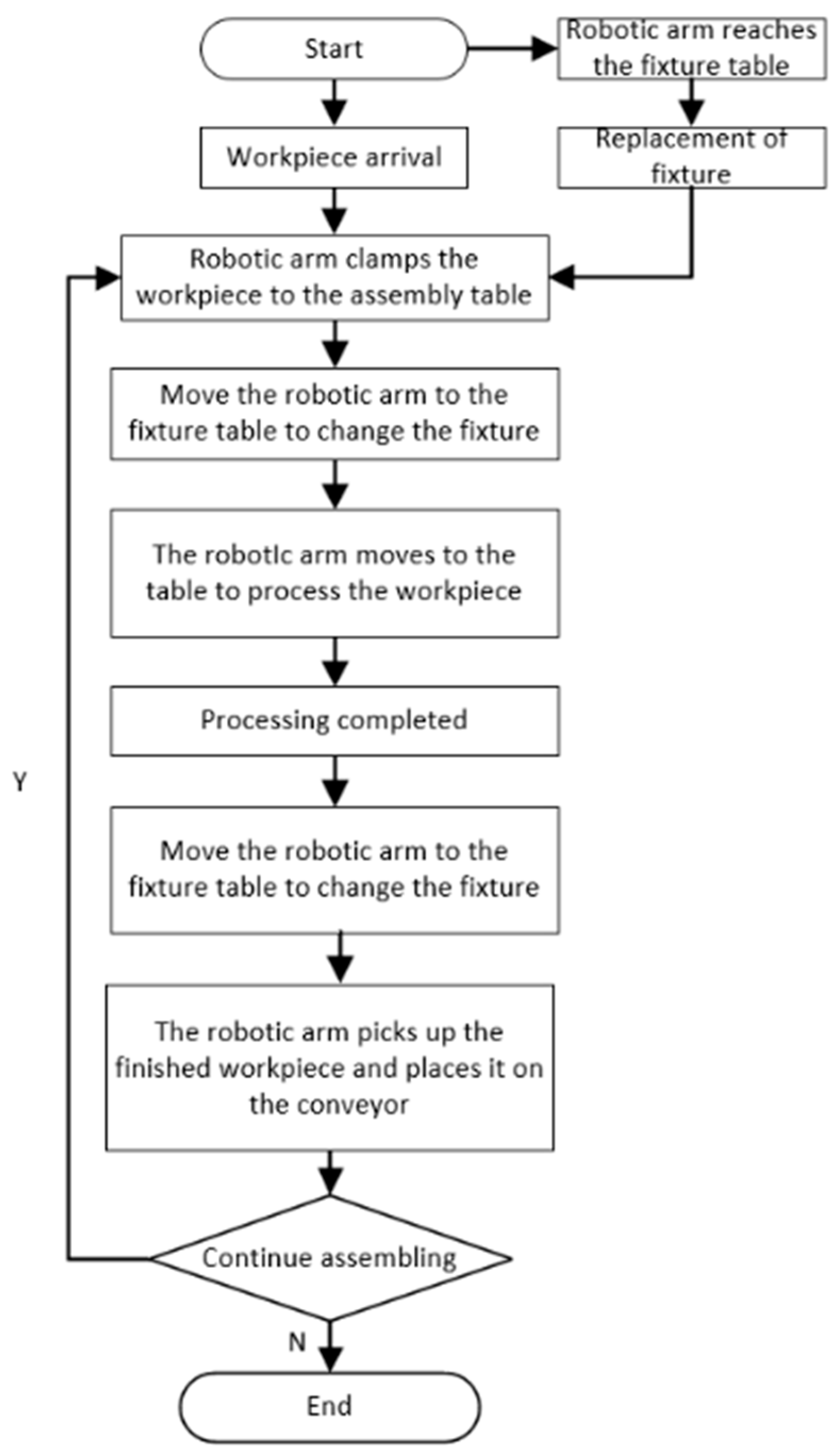
3.1. Assembly Task
According to the assembly process, the assembly flow chart is listed to give a realistic basis for the setting and selection of target points afterward. The task flow chart is shown in
Figure 1.
From the flowchart shown in
Figure 1, take the intelligent assembly test bench as an example; in order to clearly express the tasks to be accomplished by each assembly robotic arm, the total flowchart can be simplified, as shown in
Figure 2.
- 1:
The robotic arm moves from the initial position to the fixture table to change the gripper;
- 2:
The robotic arm clamps unassembled workpieces;
- 3:
The robotic arm places the clamped workpiece onto the assembly table;
- 4:
The robotic arm moves to the fixture table to replace the gripper with the screwdriver;
- 5:
The robotic arm moves to the assembly table to complete the assembly of the workpiece;
- 6:
When the assembly is complete, the robotic arm moves to the fixture table to be replaced by the gripper;
- 7:
The robotic arm returns to the assembly table to clamp the processed workpiece;
- 8:
Place the clamped workpiece onto the conveyor and wait for the next task to begin.
Based on the analysis above, we identified four target points, which are the starting points of the conveyor, assembly table, fixture table and assembly robotic arm, as well as the paths that need to be traveled to complete the assembly task. In addition, we determined that only four paths between these four target points need to be planned for motion.
3.2. IPQ-RRT* Connect Algorithm for Robotic Arms
The PQ-RRT* algorithm employs a heuristic function to guide path searching and a priority queue to expedite the process. Its primary concept is to convert the search problem into a shortest path problem, followed by utilizing a priority queue to locate the shortest possible route. However, the PQ-RRT* algorithm employs a random and disorderly approach to sampling points, inevitably leading to increased overall running time. IPQ-RRT* connect joins the node-greedy bidirectional scaling strategy, divides the process of algorithmic path search into two parts, joins the obstacle detection function, and samples according to different obstacle detection results with different random sampling methods to get rid of obstacles faster, and reduces the generation of redundant branches to speed up the efficiency of random tree expansion.
3.2.1. PQ-RRT*
The rapidly exploring random tree is a method of generating the rapidly exploring random tree in space and using random sampling and collision detection to extend its nodes, ultimately finding a collision-free path by constantly backtracking to the parent node of a particular tree node when it reaches the goal point. The PQ-RRT* algorithm adds the objective attraction function RGD and the deep parent node search function to the original RRT* algorithm. The addition of these two functions speeds up the convergence to the optimal solution and produces better initial solutions. The pseudocode for PQ-RRT* algorithm is presented in Algorithm 1.
The PQ-RRT* runs as follows:
- (1)
First, a random point is selected on the map using the SampleFree function, and then an adjusted random point is obtained by the target attraction function (RGD), under the effect of gravity at the target point. In the RGD function, the NearstestObstacle function is used to compute the Euclidean equation of the distance from to the obstacle , and the distance parameter represents the number of iterations, denotes the set distance and denotes the step size. The pseudo-code of RGD is shown in Algorithm 2. Then, the distance evaluation function Nearest is used to return the node that is positively closest to .
- (2)
Use the steer function to connect the two points and , return a line segment . After detecting no collisions with obstacles using the CollisionFree function, use the Near function to detect all nodes centered on within a radius r and return a set .
- (3)
Use the Ancestry function to search deeply into the parent nodes of all nodes in and return a set of nodes . Then, the ChooseParent function is used to compare the cost of each path and determine the node and the path based on the result of the comparison.
- (4)
Finally, the final path diagram G is generated using the Rewire-PQ-RRT* function.
| Algorithm 1: PQ-RRT* algorithm.
|
|
|
| Algorithm 2: RGD function.
|
|
|
3.2.2. Node-Greedy Bidirectional Scaling Strategy
In motion planning algorithms, the node-greedy bidirectional scaling strategy is a heuristic search strategy commonly used for robotic arm path planning. The purpose of the node-greedy bidirectional scaling strategy for robotic arms is to set up an objective function for the sampling of the sampling points in the sampling process in the three-dimensional search space in conjunction with the dual-tree strategy and use the node-greedy bidirectional scaling strategy to more efficiently find a path to the goal location from the starting point and the end point, respectively, and eventually, use the ConnectTwoTree function to connect the two trees to form a complete path. The pseudocode for the IPQ-RRT* connect algorithm is presented in Algorithm 3.
In the implementation of the algorithm for robotic arm planning, the node-greedy bidirectional scaling strategy using a node-greedy approach includes a function for detecting obstacles. Detecting obstacles during tree growth can be used to avoid unsafe situations such as collision when the robotic arm is in motion, and at the same time, it can also reduce the time and energy consumption of the robotic arm motion and improve the efficiency of the robotic arm motion.
The role of the node-greedy bidirectional scaling strategy is due to the randomly generated tree nodes being randomly distributed in the map. The generated random points are too scattered, so in order to speed up the generation of the tree, reduce the generation of redundant branches, and guide the tree to get out of the way of obstacles as soon as possible to get around the obstacles, the node-greedy bidirectional scaling strategy is added to the algorithm to improve the search efficiency of the fast search of the random tree. The pseudocode for the Greedynodes function is presented in Algorithm 4. The node-greedy bidirectional scaling strategy is applied to two trees, and the expansion process is divided into two processes in the dual-tree random point picking:
When no obstacle is detected in the obstacle detection function Objudge within the range, then the random points and are selected as the target point bias point output of and , respectively, and the target bias point will guide the two trees to grow towards the start and end points, respectively. The aim is to reduce the generation of unnecessary trees and improve the convergence.
When an obstacle is detected within dob by the obstacle detection function Objudge, the random points . and select the nodes in the other tree. and , respectively, as the target point bias point outputs, and the target bias point guides the expansion of the two trees to the other node, respectively. The aim is to get rid of obstacles faster and reduce the algorithm running time.
After going through the above two processes, two new nodes and are output, which are brought into the RGD function for further processing.
| Algorithm 3: IPQ-RRT* connect algorithm.
|
|
| Algorithm 4: Greedynodes function.
|
|
|
3.3. Model and Path Optimization
In the assembly environment, the assembly robotic arm operation process not only needs to ensure that the end-effector of the robotic arm does not collide with the obstacle but also needs to ensure that the connecting rod of the robotic arm does not collide with the obstacle; this paper uses the hierarchical wraparound box method to optimize the model of the robotic arm and the obstacle. In addition, when the IPQ-RRT* connect algorithm is used to complete the path planning, inflection points may appear in the path; these inflection points may lead to some unwanted jitter in the robotic arm during the operation process; in order to solve this problem, this paper adopts the Bezier curve method to optimize the path so that the path remains smooth.
3.3.1. Geometric Modeling of Six-Axis Robotic Arm
The collision detection between the robotic arm and the obstacle is mainly detected between each joint linkage of the robotic arm and the obstacle. In order to simplify the robotic arm model, we use cylinders and spheres to represent the robotic arm model; spheres represent some of the connecting rods, and cylinders represent other connecting rods. The simplified model of the robotic arm is shown in
Figure 3. In a real-world environment, a robotic arm may collide with the fixture table, the assembly table, and the portion of a conveyor. This is represented using a cylindrical wraparound box that matches the actual dimensions of these three obstacles. The following fixture table is chosen as an example, as shown in
Figure 4.
As illustrated in
Figure 4, obstacle detection in a robotic arm can be viewed as a distance problem between a sphere and a cylinder, as well as between two cylinders. If the distance between these geometric structures exceeds the sum of their radii, collision can be avoided. Since the collision of the robotic arm primarily occurs between the connecting rod and an obstacle, this paper examines the collision detection algorithm of the robotic arm and obstacle using the calculation of the shortest distance as an illustration.
Figure 5 shows an example.
When the robotic arm is not on the same plane as the obstacle, to determine the distance between the robotic arm’s connecting rod and the obstacle, use the neutral lines of the two cylinders, labeled as a and b. This is calculated as follows:
where
and
are the center points of the linkage and obstacle, respectively, which can be calculated using positive kinematics;
is the normal vector of the plane formed by
and
. From the above analysis, it can be seen that the problem of collision detection between the robotic arm linkage and the obstacle can be transformed into the problem of distance calculation from the centerline of the cylinder. The
parameter in the Objudge function of the node-greedy bidirectional scaling strategy is used as the distance function. When
, this indicates that there is no collision between the two cylinders. This ensures that the sampling points are at a safe distance from obstacles during the sampling process. If there is no collision relationship between all of the robotic arm’s connecting rod’s basic geometric structures and the obstacle, then it can be assumed that the robotic arm will not collide during operation. This method is computationally less intensive, making it suitable for detecting obstacles that may lead to a collision and it has the advantage of using the hierarchical wraparound box algorithm.
3.3.2. Trajectory Optimization
When the completion of the IPQ-RRT* connect algorithm is finished, some inflection points will appear, and the appearance of these inflection points may lead to the jitter problem of the robotic arm during operation, and the appearance of the jitter may lead to the damage of the equipment. In addition, the high degree of freedom joint constraints of the robotic arm may not be satisfied at some inflection points. Therefore, this paper proposes a trajectory optimization scheme by adding the Bezier curve.
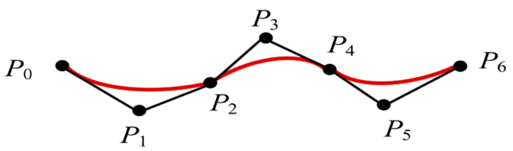
The Bezier curve is a parametric curve applied to graphics applications [
24]. This is a smooth curve plotted based on the coordinates of four consecutive points on the path. Where
is the four curvature control points,
is a Bernstein polynomial and
is a parameter that takes values from 0 to 1.
denotes the order of the curve and
denotes the control point.
Since the IPQ-RRT* connect algorithm runs with a large number of path nodes, the Bezier curve optimized smooth path order is greater than or equal to 3. Therefore, the Bezier curve fitted smooth slip path must have continuous curvature. In addition, since the higher the order of the Bezier curve, the greater the deviation of the optimized smooth curve from the original path, it may happen that the original path, which is originally safe, collides with the obstacle after the Bezier curve optimization. In this paper, by dividing the three control points in the original path into a small segment and performing segmented Bezier curve optimization on the original path, a path that meets the needs of assembly robotic arm motion planning is generated. It is shown in
Figure 6.
This method of Bezier curve optimization ensures that the optimized path is not shifted too much compared to the original path while ensuring the smoothness of the planned path. It meets the application requirements for assembly robotic arms in assembly environments.
4. Case Applications
In this study, MATLAB 2023b was used as the simulation software. The simulation results of the IPQ-RRT* connect algorithm are compared with the existing RRT*, Informed RRT*, Improved Bi-RRT*, and PQ-RRT* in two two-dimensional maps with different characteristics. It is proved that the IPQ-RRT* connect algorithm has the advantages of fast search speed, shorter search path, and stability.
In the three-dimensional environment, the target points to be passed through are specified based on the actual assembly environment. These paths are planned using the IPQ-RRT* connect algorithm. Optimize the planned paths using Bezier curves after planning is complete. After ensuring the smoothness of the paths, the model of the assembled robotic arm is optimized using the hierarchical wraparound box method. Finally, the paths are completed in the simulation environment using the simulated robotic arm.
Finally, the effectiveness of the IPQ-RRT* connect algorithm is verified by completing the assembly task in the real assembly environment.
4.1. Two-Dimensional Simulation
Due to the random nature of the sampling-based path planning algorithms. Each algorithm was run 30 times individually and the algorithm run time, trajectory length, number of iterations and number of failures were recorded. The simulations were implemented on an Intel I5 12500H CPU with 16GRAM. The test environment was the same for all three algorithms, and if a solution could not be found within 200 s, the experiment was directly recognized as a failure.
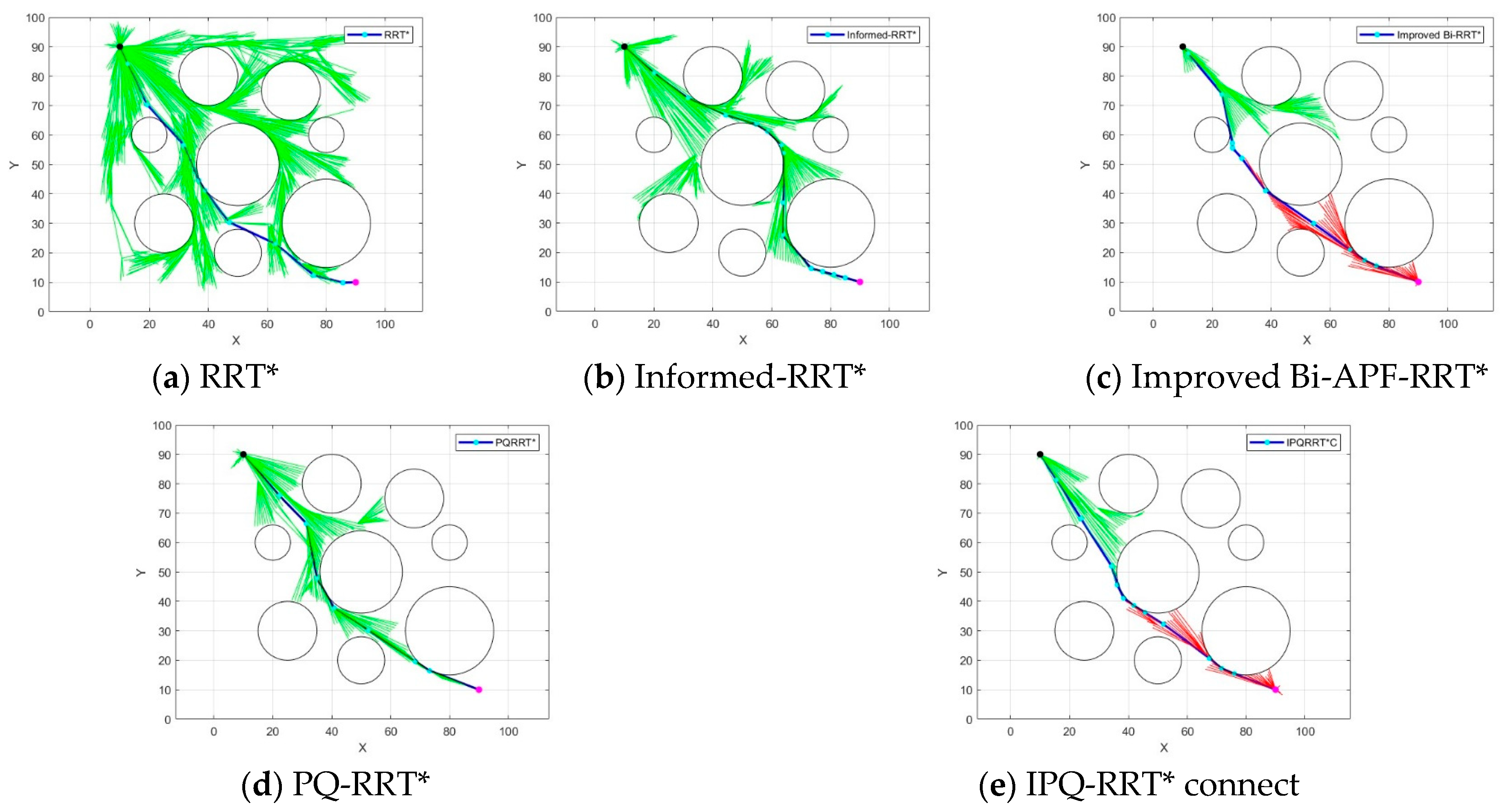
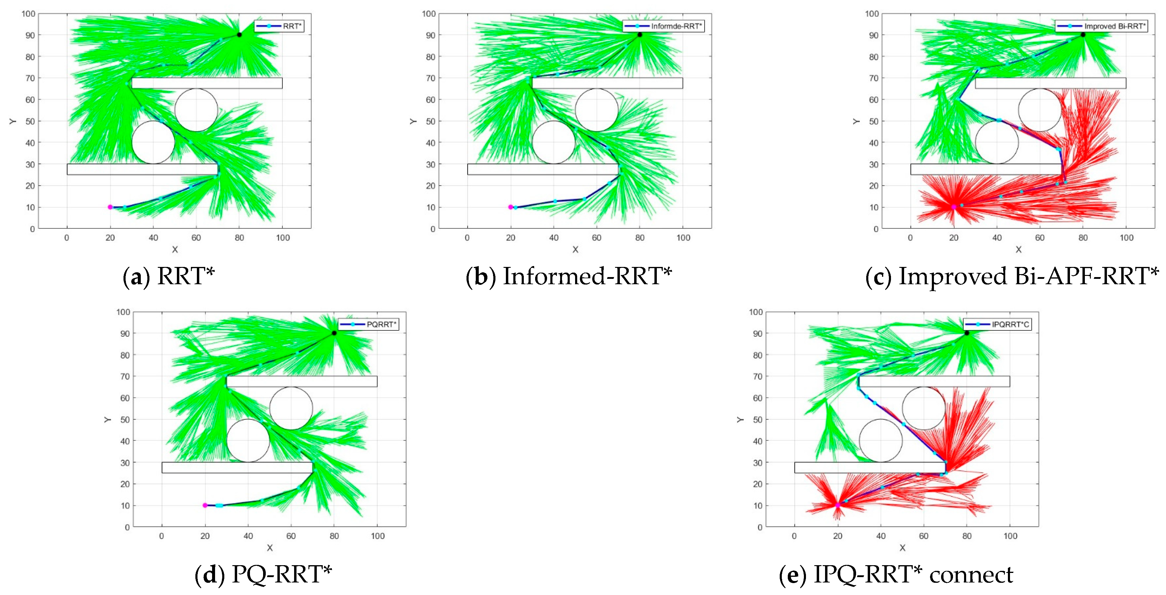
Two different two-dimensional environments were chosen, both with a map range of 100 mm × 100 mm, and the first map was set up as a unidirectional map with starting coordinates of (10, 90) and target coordinates of (90, 10). The second type of map was set up as a more complex folding line map. The starting point coordinates are (20, 10), and the target coordinates are (80, 90). In the figure, the black point and the rose red point serve as the start and end point, respectively. The blue line is the generated path after the algorithm is run. The green and red lines are the branches generated by the algorithm as it runs from the start and end point, respectively. In the first simulation environment, we set up eight black circular obstacles. The first simulation environment is shown in
Figure 7.
The results of the simulation environment (1) are shown in
Figure 7. In
Figure 7a, it can be clearly seen that due to the large number of point picking in the environment by RRT*, its final trajectory had more inflection points and longer paths. In
Figure 7b, the path length of Informed-RRT* is longer compared to that of RRT*, and the overall path is skewed towards searching above the middle circular obstacle, but its random trees grew faster, the search range was more concentrated, and the time used was shorter. Compared to Informed-RRT*, the Improved Bi-APF-RRT* algorithm in
Figure 7c added the obstacle exclusion effect and reduced some of the redundant points so that the algorithm’s search efficiency was improved, but there were still more trees in the algorithm. In
Figure 7d, the PQ-RRT* algorithm had a faster search speed compared to the Improved Bi-APF-RRT* algorithm, and the generation of redundant random trees is less. In
Figure 7e, the IPQ-RRT* connect algorithm given in this paper is shown, which had a clearer search direction, generated fewer branches and shorter paths, and met the working requirements of the robotic arm. The simulated data in the environment (1) are shown in
Table 1.
Analysis of
Table 1 shows that the IPQ-RRT* connect algorithm trajectory length was reduced by 5.24% compared to the pre-improved PQ-RRT* algorithm trajectory length. Compared to the Improved Bi-APF-RRT* algorithm, the average running time and the number of iterations were reduced by 96.97% and 56.46%, respectively. The results show that the algorithm in this paper improved the search speed and significantly reduced the generation of redundant tree branches in unidirectional search maps, also proving the stability of the algorithm. In the second simulation environment, we set up two rectangular black obstacles and two circular black obstacles. The second simulation environment is shown in
Figure 8.
Facing a more complex environment (2), the Informed-RRT* algorithm and Improved Bi-APF-RRT* experienced search failures. The IPQ-RRT* connect algorithm in this paper guarantees a shorter search time and also guarantees a shorter path length. The simulated data in the environment (2) are shown in
Table 2.
Analyzing the above table shows that the IPQ-RRT* connect algorithm trajectory length was reduced by 6.34% compared to the PQ-RRT* algorithm trajectory length before improvement. The average running time and number of iterations were reduced by 85.67% and 31.25%, respectively, compared to the Improved Bi-APF-RRT* algorithm.
In summary, it can be seen that the IPQ-RRT* connect algorithm can maintain a short search time and good path quality, whether facing the simpler unidirectional environment or the more complex folded line environment.
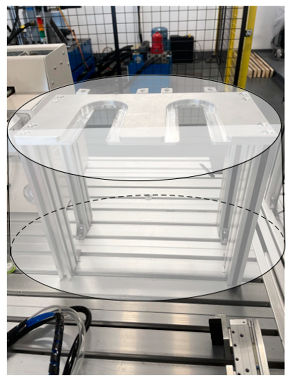
4.2. Three-Dimensional Simulation
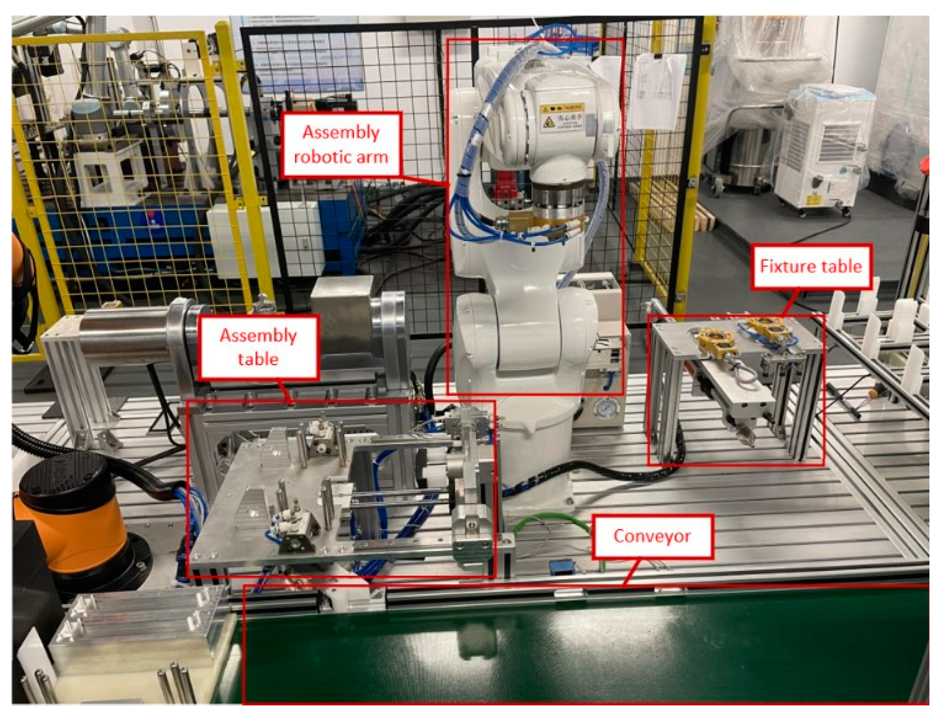
Based on the analysis in
Section 3.1, the four goal points and the paths that need to be path planned can be identified. We assume that the robotic arm end-effector position is P0, the fixture table position is set to P1, the conveyor belt position is set to P2, and the assembly table position is set to P3. We determine the coordinates of each target point in the simulation environment based on the actual position coordinates of the real assembly platform. The real assembly environment is shown in
Figure 9.
We set up a 1000 mm × 1000 mm × 1000 mm map, and in order to test the obstacle avoidance ability of the IPQ-RRT* connect algorithm in a three-dimensional environment, we set up six virtual spherical obstacles with different radii in the three-dimensional map. In addition, we set the exact position coordinates according to the target point P0 of the end-effector of the assembly robotic arm, the target point P1 of the fixture table, the target point P2 of the conveyor, and the target point P3 of the assembly table. The spatial coordinates of P0 are (500, 0, 600), the spatial coordinates of P1 are (0, 789.2, 100), and the spatial coordinates of P2 are (907.6, 612.5, 100), and the P3 space coordinates are (702.4, −200.6, 100). In the map, black dot denote the target point P1, blue dot denote the target point P2, rose-red dot denote the target point P3, and yellow dot denote the target point P4. Blue line denotes the path after the algorithm is run. The red and green lines indicate the branches generated during the running of the algorithm. Yellow spheres indicate obstacles.
The path planned by the IPQ-RRT* connect algorithm is shown in
Figure 10a. It can be found that there are many inflection points in the planning path. We used the Bezier curve method for optimization, and the optimized path is shown in
Figure 10b. It can be found that the optimized path is guaranteed to be smooth.
In the simulation robotic arm experiment, to ensure the realism of the simulation environment, the robotic arm simulation model is modeled according to the DH parameters of the real robotic arm. Inverse kinematic solution paths for each intermediate path point of the robotic arm running path using the ikine function in the Robotic Toolbox tool of MATLAB 2023b software. In the simulation map, several spherical obstacles were set to verify the obstacle avoidance ability of the robotic arm end-effector. In addition, to verify the obstacle avoidance of the linkage of the robotic arm, the assembly table, the fixture table, and the conveyor belt were set up as obstacles using the hierarchical wraparound box method in
Section 3.2.1 with cylindrical wraparound boxes. This visualized the collision and accuracy of the robotic arm. The joint angles were also recorded to check whether the robotic arm jerked during operation. In the map, red dots indicate target points. The blue line indicates the robotic arm end-effector run path. Yellow spheres and green cylinders indicate obstacles.The simulation results of the robotic arm are shown in
Figure 11.
It can be seen from
Figure 11 that the simulated robotic arm yields four collision-free and smoother paths after running the simulation. In the actual assembly process, the robotic arm end-effector only needs to follow these four collision-free paths. Under the premise of ensuring safe and fast paths, the overall efficiency of the assembly task is improved.
The joint angles of the robotic arm in the four-segment path are shown in
Figure 12.
From the analysis of the robotic arm simulation diagram, it can be seen that the end-effector and linkage did not collide with the obstacles during the operation of the robotic arm. From the analysis of the angle diagram of each joint, it can be seen that no inflection point was found in the curve of any joint. It can be demonstrated that the hierarchical wraparound box method used in the robotic arm model effectively avoided the collision of the robotic arm linkage with obstacles. The application of the Bezier curve method ensures that the generated paths are sufficiently smooth. It also avoided jittering of the robotic arm and allowed the robotic arm to run smoothly.
4.3. Real Environment Experiment
In this study, the I5 robotic arm was used to conduct experiments in a real environment. The end-effector of the robotic arm is located at a certain position in space, so it can have many possible attitudes. Since the end-attitude constraint of the robotic arm is not the focus of this paper, we chose two reasonable attitudes as the working attitudes of the robotic arm, i.e., vertical and horizontal. The robotic arm operated in a real environment, as shown in
Figure 13. The process of each assembly is explained in the red boxes in the figure.
As shown in
Figure 13a, when the workpiece reaches the specified position, the robotic arm reaches the fixture table to change the gripper; As shown in
Figure 13b, the robotic arm clamps the unassembled workpiece; As shown in
Figure 13c, the robotic arm moves to the assembly table and places the clamped workpiece to the assembly table; As shown in
Figure 13d, the robotic arm moves to the fixture table, places the gripper to the fixture table and replaces the screwdriver machine; As shown in
Figure 13e, the robotic arm moves to the assembly table and uses the screwdriver machine to assemble the workpiece; As shown in
Figure 13f, after replacing the gripper, the robotic arm places the already assembled workpiece onto the conveyor. The task of assembling the workpiece is finally completed.
During the operation of the robotic arm, the robotic arm operated smoothly without sudden changes. Finally, the assembly task was completed.


