
Hybrid Nursing Robot Based on Humanoid Pick-Up Action: Safe Transfers in Living Environments for Lower Limb Disabilities
1
School of Artificial Intelligence, Anhui University of Science & Technology, Huainan 232001, China
2
Anhui Artificial Intelligence Laboratory, Artificial Intelligence Research Institute of Hefei Comprehensive National Science Center, Hefei 230000, China
3
School of Mechanical Engineering, Anhui University of Science & Technology, Huainan 232001, China
*
Author to whom correspondence should be addressed.
Actuators 2023, 12(12), 438; https://doi.org/10.3390/act12120438
Submission received: 9 October 2023
/
Revised: 20 November 2023
/
Accepted: 23 November 2023
/
Published: 24 November 2023
(This article belongs to the Special Issue Advanced Robots: Design, Control and Application—2nd Edition)
Abstract
:This research paper outlines the development of a modular and adjustable transfer care robot aimed at enhancing safe and comfortable transfers for individuals with lower limb disabilities. To design this robot, we utilized a 3D motion capture system to analyze the movements of a person assisting another person and to determine the necessary range of motion and workspace for the robot. Based on this analysis, we developed a 3-UPS + UPR parallel spreader to transfer the person receiving care. We also conducted kinematic and dynamic analyses of the parallel spreader to validate its operational space and to obtain the force change curve for the drive. To evaluate the robot’s performance, we enlisted the help of ten volunteers with varying heights and weights. Our findings indicate that the pressure distribution during transfers remained largely consistent. Additionally, the surveys revealed that those receiving care perceived the robot as being capable of securely and comfortably transferring individuals between different assistive devices. This modular and adaptable transfer assistance robot presents a promising solution to the challenges encountered in caregiving.
1. Introduction
With the aggravated aging of the population, the number of disabled/semi-disabled persons is increasing, which causes many social problems, such as the lack of care and increased bodily injuries to nursing persons [1,2,3]. For disabled/semi-disabled persons, nursing services include transfer support, excretion support, guardian support, and spiritual consolation, wherein transfer support poses the most serious risk of bodily injury to the nursing person [4,5]. Transfer support refers to the heavy physical work of assisting or carrying a disabled person to transfer them between living appliances such as a bed, wheelchair, a close stool, or sofa. It is a key factor that causes home nursing difficulty, disharmonious family relationships, and other social problems [6].
The common transfer carriers are divided into direct and indirect carriers [7]. Direct carriers adopt a bed–wheelchair integrated design. Based on the Internet of Things (IoT), Muangmeesri and Wisaeng [8] designed an intelligent wheelchair with a health monitoring function. Zhou et al. [9] designed an intelligent nursing bed that integrates the functions of a traditional nursing bed and a powered wheelchair. Lang et al. [10] developed a smart nursing bed designed to facilitate automatic defecation for patients. Nevertheless, the expensive and non-transferable equipment transfer approach poses limitations, as it does not enable transfers between various devices. At present, the indirect carrier is the popular transfer carrier. Wang et al. [11] designed a power-driven transfer device that uses a sling to lift and move a nursed person. It is simple and cheap, but it is less comfortable and can easily cause secondary injury. The RI-MAN humanoid bilateral-arm rehabilitation robot [12] designed by the RIkagaku KENkyusho/Institute of Physical and Chemical Research has 19 degrees of freedom (DOFs) and contains two coupled six-DOF robotic arms and multiple sensors for the rapid perception of the external environment. The second generation of the robot nursing assistant (RoNA) launched by HStar [13,14] adopts a tandem elastic drive system that effectively guarantees the safety and flexibility of two arms and has a loading capacity of 227 kg. It is also equipped with a three-dimensional (3D) intelligent navigation system. Its shortcoming is that it requires the assistance of two medical care personnel and is thus less efficient. Zhang et al. [15] created a nursing robot with an aluminum alloy structure by focusing on the center of gravity. This robot can move safely and efficiently along a predefined path between two work points. However, the use of motor-driven arm joints proves to be expensive and unsuitable for widespread adoption. Liu et al. [16] developed a humanoid back-holding transfer rehabilitation robot that uses a three-DOF chest support to support the chest of a nursing person while it carries the nursed person on its back for transfer. However, this robot is complex and large. To sum up, the existing transfer equipment, aimed at ensuring the safety and comfort of care, comes with elevated costs and equipment complexity. This high price tag poses challenges for the broader population to afford such equipment [17,18,19].
Simultaneously, the emotional well-being of an individual receiving care and their comfort during the transfer process play significant roles in caregiving. Previous studies [12,13,14] have employed humanoid robots, demonstrating that human-like movements can enhance the emotional connection between the robot and the individual while improving comfort. However, none of the aforementioned studies analyze the movements of a person embracing another individual, instead opting for a costly robotic arm with multiple motors.
To create a transfer care robot that is safe, comfortable, and cost-effective while mimicking the anthropomorphic hugging and transferring motions, our approach involved using a 3D motion capture system to analyze human hugging movements and determine the necessary range of motion and workspace for the robot. Building on this analysis, we developed a hybrid transfer robot equipped with a 3-UPS + UPR parallel spreader designed for optimal structural stability. To ensure the functionality and safety of the designed robot, we conducted kinematic and dynamic analyses. Subsequently, we fabricated a prototype and conducted experiments with recruited volunteers. The results demonstrated the robot’s ability to comfortably transfer caregivers between chairs, beds, sofas, wheelchairs, and other everyday living appliances. This success suggests the potential for the widespread application of this innovative robot.
2. Analysis of the Pick-Up Action
In this study, we employed a 3D motion capture system to determine the necessary degrees of freedom for our mechanism’s design and its range of motion. Additionally, we conducted tests involving several individuals who require care to establish the required workspace, tailored to the needs of a wide range of individuals. The specific body parameters for individuals who can benefit from this robot’s assistance are outlined based on the inertial parameters defined by the General Administration of Quality Supervision, Inspection and Quarantine of the People’s Republic of China, China National Committee for Standardization [20]. These parameters include a height range of 1500 mm to 1880 mm and a weight range of 50 KG to 90 KG.
2.1. Design of the Pick-Up Test
In this test, a NOKOV optical 3D motion capture system was used to capture the actions of the nursed person in the pick-up process [21,22]. According to the standard human skeleton model [23] given in the ISO/IEC19774-Human animation (H-Anim) standard, “r_shoulder”, “l_shoulder”, “vl5”, and “sacroiliac” in the model were selected as the markers (Figure 1). As shown in the figure, a nursed person sat on a chair, and a nursing person picked up the nursed person and moved them by walking.
The nursed persons were five volunteers with different heights and weights, as shown in Table 1. The first nursing person was a male, aged 23, 1750 mm in height, and 85 kg in weight. To avoid daytime sunshine from affecting the motion capture, the test was conducted at night. Before the test, the nursed persons and the nursing person did not drink, but they had a good rest. In addition, to prevent the physical fatigue caused by the continuous tests from affecting the pick-up action, the nursed persons and the nursing person were asked to take a 10 min break before participating in the next set of tests.
2.2. Analysis of the Pick-Up Action
The pick-up and transfer actions, illustrated in Figure 2, included four stages: approaching, picking up, steady movement, and lowering. First, the nursed person sat on a chair, and the nursing person approached the nursed person and bent to an appropriate position. Second, the nursing person maintained their leg posture when approaching the nursed person, put their arms on the back and thighs of the nursed person, and then stood up. In this process, the back angle of the nursed person changed a little. Third, the nursing person adjusted the posture of the nursed person to a “comfortable” state and leaned the body of the nursed person backward. Fourth, the nursing person leaned the nursed person’s body frontward and slowly lowered them down into the chair.
A coordinate system was established by considering the body of the nursed person as a rigid rod and considering the projection center of the chair on the ground as the origin (Figure 3). Using an example of a person being cared for who has a height of 1700 mm and a weight of 72 kg, the entire lifting process takes 18 s. During this process, we observed the change in the angle between the cared-for person’s body and the X-axis, as illustrated in Figure 4. The nursed person’s subjective feeling in the pick-up process was affected by their posture and the change in the interaction between the two persons due to the posture variation; when the said angle was within 10°–25°, the nursed person felt “comfortable” as the forces on their back, legs, and other contact parts were acceptable [24].
Figure 5 provides the minimum trajectory ranges of the markers on the five nursed persons. The vertical displacement of each marker was nondimensionalized by the corresponding nursed person’s height as the denominator. The smallest trajectory range covers 640 mm horizontally and 280 mm vertically. These minimum trajectory ranges are crucial for designing the workspace of the robot. A requirement is that the workspace of the sling used in this innovative design should be greater than the minimum trajectory range.
The test results revealed that the forces on the nursed person changed with the change in the nursing person’s posture, which directly affected their comfort. Therefore, based on the features of the pick-up action, the robotic pick-up sling should have three DOFs (for horizontal movement, vertical movement, and rotation), as shown in Figure 6.
3. Hybrid Robot: Structure and Functionality
As illustrated in Figure 7, The modular hybrid robot, described in this paper, incorporates several components including a mobile chassis, a 3UPS + UPR parallel spreader, a linear skid module, a binocular vision system, a protective hood, a slewing device, and a lifting device. Its dimensions are 1000 mm × 700 mm × 1750 mm, supporting a load capacity of 50 KG to 90 KG. These specifications stem from an in-depth analysis of the physical characteristics of the intended user group, detailed in Section 2. The focus of this research centers on the 3-UPS + UPR parallel spreader.
The 3-UPS + UPR’s three-dimensional movement is facilitated by adjusting the lengths of the four electrically driven rods. These rods offer a motion range of 0–350 mm, a maximum thrust of 2500 N, and a telescopic speed of 7 mm/s. Coupled with the horizontal slide movement, this mechanism allows for precise positioning relative to the caregiver. The module’s design prioritizes structural integrity and stability, effectively replacing traditional multi-joint robotic arms. This aspect is crucial in minimizing the risk of mechanical failures during operation, thereby safeguarding the user’s safety during transfer processes.
The work process of this robot is as follows: when detecting a nursed person, the binocular vision system moves the mobile chassis to a designated position and adjusts the 3-UPS + UPR paralleled sling to a position that is wearable for the nursed person through the rotatory device, lifting device, and straight pulley block modules; when the nursed person wears the sling well, the paralleled sling can pick up the nursed person and adjust the postures until the transfer nursing process is finished.
In response to the requirements identified during the analysis of pick-up and carry movements, the 3-UPS + UPR parallel spreader is designed to offer three essential degrees of freedom: horizontal movements, vertical movements, and rotational capability. This design specifically addresses the diverse mobility needs of individuals with lower limb disabilities.
As illustrated in Figure 8, the 3-UPS + UPR paralleled mechanism is composed of a fixed platform, a mobile platform, three identical UPS branches (hooke joint (U), sliding pair (P), and spherical joint (S)), and a UPR branch. The four branches are distributed like a square on the fixed platform.
4. Kinematic Analysis
To confirm whether there is a sudden change in the driving force of the parallel mechanism during the holding motion, which could be potentially hazardous, a kinematic analysis is required. This analysis will help to derive the position inverse solution and the Jacobian matrix for the parallel mechanism, establishing the groundwork for a subsequent dynamic analysis. Simultaneously, it is essential to determine the workspace to ensure that it exceeds the minimum trajectory range required for the cared-for person.
4.1. Inverse Solution for Positions
To pick up a person with the robotic 3-UPS + UPR paralleled sling, the kinematic parameters of the sling were calculated based on the trajectory of the humanoid pick-up motion. Further, the topological structure of the 3-UPS + UPR paralleled sling was established, as shown in Figure 9.
A base coordinate system (O) is established at the center of the fixed platform, where the center of the square is the origin O, the X-axis is parallel to line A1A3, the Y-axis is parallel to line A2A4, and the Z-axis is vertical to face A1A2A3A4; a moving coordinate system (o) is established at the center of the mobile platform, with the origin o at the center of the square mobile platform, the x-axis parallel to line B1B3, the y-axis parallel to line B2B4, and the z-axis vertical to face B1B2B3B4. In this paper, the first shaft Ri1(i = 1,2,3,4) of each hooke joint is along the Z-axis direction and vertical to the second shaft Ri2(i = 1,2,3,4), the second shaft Ri2 of each hooke joint is vertical to the driving pair Pi of each branch, the second shaft R12 of the hooke joint in the UPR branch is vertical to the R13, and the rotating axis of R13 is parallel to the x-axis of the mobile platform.
As for the inverse kinematic of the position of the 3-UPS + UPR mechanism, the length vector of the drive rod in each branch of the mechanism was determined by using a rotation matrix and constraint equation, given that the length from the center to the vertex of the fixed platform is , the length from the center to each vertex of the mobile platform is , and the pose of the center o of the mobile platform relative to the fixed coordinate system is For the 3-UPS + UPR paralleled mechanism, the constraint equation is determined, as shown below, based on the geometrical relationships of the revolving pairs R12⊥A1B1, R12⊥R13, R11⊥R12, and R13⊥A1B1:
The variables , , , and are set, representing the unit direction vectors of , , , and in the base coordinate system, and is set as the length of the revolving pair, where
The pose transformation matrix of each vertex Bi on the mobile platform in the base coordinate system is
According to the position transformation relation, the direction vector of the vector hi in the base coordinate system (O) can be expressed as
Hence, the coordinates of each vertex on the mobile platform in the base coordinate system are obtained as follows: is the coordinate of a vertex on the mobile platform in the base coordinate system, is the pose transformation matrix of each vertex on the mobile platform in the base coordinate system, is the coordinate of the vertex on the mobile platform in the moving coordinate system, and is the coordinate of the vertex on the mobile platform in the base coordinate system.
Thus, the vector equation of each branched mobile chain in the 3-UPS + UPR paralleled mechanism is established as shown below:
In combination with the constraint equation, the rotation matrix, and the vector equations of the branches, the position inverse kinematic expression of the 3UPS + UPR paralleled mechanism is obtained as shown below:
4.2. Solution of the Jacobian Matrix
The first-order influential factor matrix of the mechanism was calculated using the differential transform method based on the symbolic operation. Then, the first-order motion influential factors were used to solve the velocity Jacobian matrix of the 3-UPS + UPR paralleled mechanism. According to the motion feature of the mechanism, the length of the drive rod can be expressed as
By calculating the derivative of time based on the above equation, the velocity of the drive rod in each branched chain is obtained as follows:
Hence, the mapping relationship between the velocity of the mobile platform and the driving velocity can be expressed as
Let and . Then,
where is the velocity of the drive rod, J is the 1-order influential factor matrix of the mechanism, which is written as , and is the motion velocity of the mobile platform. The Jacobian matrix of the 3-UPS + UPR paralleled mechanism has four rows and three columns.
4.3. Analysis of the Workspace
The pose adjustability of the paralleled sling depends on the workspace of the paralleled mechanism. To realize “global” pose adjustment for a nursed person, the reachable workspace of the mechanism can be calculated with a numerical method and analytical method. However, the latter method requires an explicit expression of the position solution of the mechanism and has a complicated calculation process and high cost. Hence, the numerical method was used to calculate the flexible workspace of this mechanism.
The workspace of the 3-UPS + UPR paralleled sling is affected by the structural dimension of the mechanism, the rotation angle limit of the revolving pair, and the interference of the connecting rods. The dimensions of the platforms in the mechanism are listed in Table 2.
The constraint conditions are as follows: (a) the travel of the driving pair ranges within 320 mm–600 mm; (b) the rotation angles (, and λ) of the hooke joint and spherical joint are limited to ±25°.
The following displays the process flow in calculating the workspace of the paralleled mechanism with the numerical method:
- Set the pre-workspace of the mechanism and divide the uniform step size equally.
- Substitute the position parameters and posture rotation angle in the workspace into the constraint equation and establish a system of nonlinear equations.
- Use the homotropy method to obtain multiple groups of numerical solutions, then compare this set of solutions with the preset constraint conditions, and screen out the correct solution.
- All solutions satisfying the constraints in the pre-workspace are reachable workspaces, as presented in Figure 10.
Meanwhile, the SoildWorks software was used to verify the correctness of the workspace of the paralleled mechanism based on the numerical solution, with the following major process flow:
- Establish a 3-UPS + UPR paralleled mechanism model in the SoildWorks software.
- Read and tabulate the equal division points in step 1 of the numerical solution, and then use Visual Studio to compile an EXE file, and read the elongation of each rod and the angle of the shafts of the revolving pair while inputting all points in the table into the center of the mobile platform of the mechanism successively.
- Delete the point locations that cannot be generated by SoildWorks, screen out the points satisfying the constraint equation, and reserve the remaining points.
- Generate the remaining points into curves in SoildWorks and seam the curved surfaces, obtaining the workspace, as provided in Figure 11, and the volume parameter.
As discovered by comparing the workspace figure obtained based on the numerical solution with the simulated diagram, the simulated workspace is identical to the calculated workspace, which proves that the conducted work is correct. Further, the inscribed cylinder in the workspace, as shown in the reachable workspace figure, was calculated, obtaining a task workspace with a diameter of 650 mm and a height of 300 mm. The workspace of the robot exceeds the minimum trajectory required for the individual receiving care. This result verifies that the designed robot sling satisfies the transfer demands of most nursed persons.
5. Dynamical Analysis and Simulation
To ensure the safety of the transfer process for the individual receiving care and to avoid abrupt changes in the driving force, a dynamic analysis of the 3-UPS + UPR parallel mechanism is conducted using the principle of virtual work. The parameters for the moving platform position are determined based on the humanoid hold-and-take action, enabling us to derive the curve depicting changes in its driving force.
5.1. Dynamical Analysis
Performing a dynamical analysis of a paralleled mechanism based on the principle of virtual work is one of the analysis methods for such systems [25,26,27]. This method involves a high calculation speed and low complexity, without calculating the constraining force and moment. Thus, the principle of virtual work has been used to analyze the dynamics of the 3-UPS + UPR paralleled mechanism.
The mass, , of the mobile platform; the external force, , and the moment, , on the barycenter of the mobile platform; and their references, and , in the fixed coordinate system are given as follows: and .
Taking as the inertial matrix of the mobile platform in the mobile coordinate system, the inertial matrix of the mobile platform in the fixed coordinate system is expressed as .
The relationship between the force and moment on the barycenter of the mobile platform is expressed as
When each branched chain only bears gravity, given the mass of the drive rod in a branched chain, its inertial matrix in the branched system is represented as . The force and moment on the branched chain are indicated as
Based on Equations (12) and (13), the dynamical equation of the mechanism is established based on the principle of virtual work as follows:
where is the virtual displacement of the mobile platform, is the driving force, is the virtual displacement of the driving force, and is the virtual displacement corresponding to .
The virtual displacement shown in Equation (14) and the generalized virtual displacement of the mechanism satisfy the geometric constraints of the 3-UPS + UPR mechanism itself, and their relationships can be denoted as and . Equation (14) can be written as
Equation (15) is satisfied for any . Hence,
In Equation (16),
, , and are the pseudo-inverse matrix of , the base vector of the null space, and the base vector coefficient of the null space, respectively. In other words, Equation (17) can be treated as the dynamic model of this mechanism. For the 3-UPS + UPR redundancy parallel mechanism, Equation (17) comprises three linear equations, which, however, have four unknown numbers. Hence, the solutions of these equations are not unique. Based on the two-norm solution of the driving force, Equation (17) can be denoted as
5.2. Numerical Simulation for Verification
The simulation performed using MATLAB and the ADAMS software was carried out to verify the validity of the kinematic and dynamical models established for the paralleled mechanism. The parameters of the 3-UPS + UPR paralleled mechanism (Table 2) were determined as per the work requirement and workspace of the transfer nursing robot.
Utilizing the trajectory of the humanoid pick-up motion, we made an assumption regarding the pose parameters of the mobile platform.
The driving force curves of the drive rods in the 3-UPS + UPR paralleled mechanism were calculated based on the motion trajectory of the mobile platform and the aforementioned kinematic and dynamical equations. Figure 12 shows the driving force curves calculated using Matlab, and Figure 13 shows the driving force curves simulated using ADAMS, where the step size was 0.2 s and the calculation time was 20 s. The results reveal that the driving force varied continuously and steadily such that the nursed person could be transferred steadily. The theoretically calculated results were almost equal to the simulated results, with a maximum error of 3%, which is allowable. Hence, it was proven that the dynamical model of the mechanism is valid.
6. Functional Test and Analysis of the Prototype
6.1. Functional Test
The series-parallel transfer nursing robot has been designed mainly for transferring a person with healthy upper limbs and disabled lower limbs between different living appliances. In this test, we selected ten young adults aged 20–35 with different heights and weights (Table 3), but with healthy upper limbs and disabled lower limbs, to experience the transfer function of the robot designed in this study.
The study was approved by the Biomedical Research Ethics Committee of Anhui University of Science and Technology (Anhui, China) in accordance with the Declaration of Helsinki. All methods were carried out in accordance with relevant guidelines and regulations. Written informed consent was obtained from all individual patients included in the study.
The transfer nursing process of a test subject with a height of 1750 mm and a 70 kg weight (the nursed person), as an example, is illustrated in Figure 14. At the beginning, the nursed person adjusted his sitting posture and the chair height as per his subjective feeling. Once the preparatory work was finished, in the course of nursing, the parallel spreader was shifted to the individual being cared for using the lifting device and the linear slide module. This movement was carried out in accordance with the position described in the previous section for adjusting the humanoid holding action mechanism. The nursing staff assisted in placing the individual on the spreader. The parallel spreader adapted the length of the individual drive rods based on the posture parameters of the humanoid lifting action, simulating the lifting action to raise the cared-for person. After that, the nursed person moved his head to the protective hood and laid flat, entering a steady convey stage (Figure 14a–c). After approaching the ward bed, the sling was used to readjust the lengths of the drive rods and lower the nursed person down onto the bed slowly (Figure 14d–e). At this time, the transfer nursing was finished.
In this functional test, the robot completed the transfer of ten test objects successfully and the test objects also gave good feedback without adverse reactions.
6.2. “Comfort” Test
In the transfer process, the forces on the parts of the nursed person contacting the robot were the direct factors affecting their comfort. The pressure on their back changed with the change in the posture of the 3-UPS + UPR paralleled sling. The vibration in the movement also contributed to the pressure change. Therefore, arrayed flexible tactile sensors were provided on the contact parts (back) between the sling and the nursed person, and a pressure acquisition system was used to record the change in the pressure distribution on the backs of the ten test subjects during the transfer.
At the beginning of the test, the test subjects adjusted the chair height and position as per their specific heights and subjective feelings. Then, the robot’s motion trajectory was designed based on each test subject’s subjective feeling, respectively. According to the motion modes of the robot, the transfer was divided into four stages: the starting stage (the nursed person leaves the chair), the lifting stage, the steady stage, and the lowering stage. Figure 15 exhibits the pressure changes on the ten test objects in the four stages, where the maximum pressure was 26.6 kPa, the minimum pressure was 4.5 kPa, and the maximum variation was 24.1 kPa. A person can noticeably feel a pressure change of 24.1 kPa, which falls within the normal acceptable range. In the test, the test subjects’ pressure distributions changed less in four states, with an average pressure variation of 5.2 kPa/s. Therefore, their pressure distributions wereless affected by the change in the posture of the 4-UPR sling and the vibration during transferring. This result verifies that this prototype is stable and can transfer a nursed person comfortably.
As pain or comfort is based on the subjective judgment of individuals, a questionnaire survey and analysis was also made on whether the nursed persons felt “comfortable” or not in the test stages. In the subjective comments, the nursed persons’ comfort degrees were divided into four levels: “uncomfortable”, “acceptable, “good”, and “comfortable”. The comfort degree comments of the nursed persons in the stages are exhibited in Figure 16. As can be seen in Figure 16, the nursed persons did not feel uncomfortable in the starting stage and steady stage; one nursed person felt uncomfortable in the lifting stage, and two nursed persons felt uncomfortable in the lowering stage; and no nursed person felt uncomfortable in the whole transfer process, and those who felt good and comfortable accounted for 80%. The pressure distribution test and subjective comments all reveal that most nursed persons feel comfortable in the test process. Hence, the designed robot can transfer a nursed person comfortably.
7. Conclusions
This paper examines the action of humanoid hugging and employs this analysis to design a hybrid shift-riding care robot. To begin, a 3D motion capture system is utilized to record the human hugging action, allowing for an analysis of the movement path of the person being cared for. This analysis yields information on the degrees of freedom and workspace relevant to this action. Subsequently, a transfer-riding nursing robot with a 3-UPS + UPR parallel mechanism is devised. Kinematics and dynamics are employed to assess the workspace and stability of the robot. The results indicate that the robot’s workspace exceeds the minimum trajectory range required for caring for the individual, meeting the necessary nursing care standards. Furthermore, during the humanoid-carrying motion, the driving force in each branch of the parallel mechanism transitions smoothly, without sudden changes, thus fulfilling stability requirements. In a prototype experiment, all volunteers report positive experiences when the robot performs humanoid holding care, and the change in the back pressure remains within an acceptable range. This robot offers convenience and reduces the workload of caregivers.
In contrast to the dual-arm humanoid care robot, this robot utilizes a hybrid plus modular structural design, providing improved structural stability at a lower cost. In the future, we plan to enhance the robot’s structure, develop more advanced control algorithms, and undertake clinical validation to better address caregivers’ requirements.
Author Contributions
J.L.: conceptualization, writing—original draft, writing—review and editing, data curation, formal analysis, and visualization. C.W.: conceptualization, methodology, writing—review and rditing, supervision, and resources. H.D.: writing—review and editing, data curation, and investigation. All authors have read and agreed to the published version of the manuscript.
Funding
This work was supported by the University Synergy Innovation Program of Anhui Province (grant numbers GXXT-2022-053); Anhui New Era Education Quality Project (Graduate Education); Provincial Graduate students “Innovation and Entrepreneurship Star” (grant number 2022cxcyzx127); and Huainan City science and technology plan project (grant number 2021A242).
Institutional Review Board Statement
This study was approved by the Biomedical Research Ethics Committee of Anhui University of Science and Technology (Anhui, China) in accordance with the Declaration of Helsinki. All methods were carried out in accordance with relevant guidelines and regulations. Written informed consent was obtained from all individual patients included in the study.
Data Availability Statement
The datasets used and analyzed during the current study are not available for public disclosure and are available from the corresponding authors upon reasonable request.
Acknowledgments
The authors thank the volunteers who contributed to the experiment.
Conflicts of Interest
The authors declare no conflict of interest. The funders had no role in the design of the study; in the collection, analyses, or interpretation of data; in the writing of the manuscript; or in the decision to publish the results.
References
- van Dam, K.; Gielissen, M.; Reijnders, R.; van der Poel, A.; Boon, B. Experiences of Persons With Executive Dysfunction in Disability Care Using a Social Robot to Execute Daily Tasks and Increase the Feeling of Independence: Multiple-Case Study. JMIR Rehabil. Assist. Technol. 2022, 9, e41313. [Google Scholar] [CrossRef]
- Pedace, C.; Rosa, A.; Francesconi, P.; Acampora, A.; Ricciardi, W.; Damiani, G. Governance in a project addressing care of disabled elderly persons within the regional healthcare system of Tuscany, Italy. Ig. Sanita Pubbl. 2017, 73, 351–372. [Google Scholar] [PubMed]
- Moon, C.H.; Groman, R.; Jasak, R.S.; Burnetta, E.C.; Gonzalez-Fernandez, M.; Annaswamy, T.; Jayabalan, P.; Venesy, D.A.; Sereiko, T.J.; Flanagan, S.R. PM&R BOLD: The American Academy of Physical Medicine and Rehabilitation’s strategic initiative to envision—And effectuate—The future of care across the rehabilitation care continuum. PM&R J. Inj. Funct. Rehabil. 2022, 14, 1497–1508. [Google Scholar] [CrossRef]
- van Rooijen, M.; Lenzen, S.; Dalemans, R.; Beurskens, A.; Moser, A. Stakeholder engagement from problem analysis to implementation strategies for a patient-reported experience measure in disability care: A qualitative study on the process and experiences. Health Expect. 2021, 24, 53–65. [Google Scholar] [CrossRef] [PubMed]
- Yang, K.; Lan, L.; Shen, P.; Wen, X.; Yue, P.; Luo, L. Application of APN model based on nursing studio in home rehabilitation of patients with ischemic stroke. Chin. Nurs. Res. 2022, 36, 3906–3911. [Google Scholar]
- Garg, A.; Lobner, K.; Mitchell, R.; Song, J.; Egbunine, A.; Kudchadkar, S.R. PP324 [Critical Care Rehabilitation» Rehabilitation]: Health disparities in pediatric rehabilitation: A systematic review. Pediatr. Crit. Care Med. 2022, 23, 11S. [Google Scholar] [CrossRef]
- Mireles, C.; Sanchez, M.; Cruz-Ortiz, D.; Salgado, I.; Chairez, I. Home-care nursing controlled mobile robot with vital signal monitoring. Med. Biol. Eng. Comput. 2023, 61, 399–420. [Google Scholar] [CrossRef]
- Muangmeesri, B.; Wisaeng, K. IoT-Based Discomfort Monitoring and a Precise Point Positioning Technique System for Smart Wheelchairs. Appl. Syst. Innov. 2022, 5, 103. [Google Scholar] [CrossRef]
- Zhou, S. Research on Design and Key Technologies of Compound Intelligent Nursing Bed. Master’s Thesis, Jiangnan University, Wuxi, China, 2018. [Google Scholar]
- Lang, J.; Zhang, Z.; Zhao, J. Mechanical analysis and simulation of intelligent nursing bed. IOP Conf. Ser. Mater. Sci. Eng. 2019, 677, 022069. [Google Scholar] [CrossRef]
- Wang, C.; Hu, K.; Wang, X.; Dai, R. Design and kinematics simulation analysis of disabled shifter. Mach. Design Manuf. 2020, 11, 279–283. [Google Scholar] [CrossRef]
- Qassim, H.M.; Wan Hasan, W.Z. A Review on Upper Limb Rehabilitation Robots. Appl. Sci. 2020, 10, 6976. [Google Scholar] [CrossRef]
- Narayanan, K.L.; Krishnan, R.S.; Son, L.H.; Tung, N.T.; Julie, E.G.; Robinson, Y.H.; Kumar, R.; Gerogiannis, V.C. Fuzzy Guided Autonomous Nursing Robot through Wireless Beacon Network. Multimed. Tools Appl. 2021, 81, 3297–3325. [Google Scholar] [CrossRef] [PubMed]
- Cao, S.; Kazuki, N.; Quan, C.; Luo, Z. On robotic rehabilitation of human dual arms’ coordinative function. Int. J. Appl. Electromagn. Mech. 2016, 52, 943–950. [Google Scholar] [CrossRef]
- Zhang, L.; Gao, H.; Xu, H.; Song, J. Trajectory planning of the nursing robot based on the center of gravity for aluminum alloy structure. Rev. Adv. Mater. Sci. 2021, 60, 731–743. [Google Scholar] [CrossRef]
- Liu, Y.; Guo, S.; Chen, G.; Liu, J.; Gan, Z. Bionic motion planning and the analysis for human comfort of a piggyback nursing-care robot for transfer tasks. J. Mech. Eng. 2020, 56, 147–156. [Google Scholar]
- Nielsen, S.; Langensiepen, S.; Madi, M.; Elissen, M.; Stephan, A.; Meyer, G. Implementing ethical aspects in the development of a robotic system for nursing care: A qualitative approach. BMC Nurs. 2022, 21, 180. [Google Scholar] [CrossRef] [PubMed]
- Lim, M.J.; Song, W.K.; Kweon, H.; Ro, E.R. Care robot research and development plan for disability and aged care in Korea: A mixed-methods user participation study. Assist. Technol. 2022, 35, 292–301. [Google Scholar] [CrossRef]
- Ohneberg, C.; Stöbich, N.; Warmbein, A.; Rathgeber, I.; Fischer, U.; Eberl, I. Potential Uses of Assistive Robotic Systems in Acute Inpatient Care. Stud. Health Technol. Inform. 2022, 294, 801–802. [Google Scholar] [CrossRef]
- GB/T 17245-2004; Inertial Parameters of Adult Human Body. Standardization Administration of China: Beijing, China, 2004.
- Xu, C.; Wang, X.; Duan, S.; Wan, J. Spatial-temporal constrained particle filter for cooperative target tracking. J. Network Comput. Appl. 2021, 176, 102913. [Google Scholar] [CrossRef]
- Chen, W.; Li, Z.; Cui, X.; Zhang, J.; Bai, S. Mechanical design and kinematic modeling of a cable-driven arm exoskeleton incorporating inaccurate human limb anthropomorphic parameters. Sensors 2019, 19, 4461. [Google Scholar] [CrossRef]
- ISO/IEC FCD 19774: 200x; Humanoid Animation, Annex B, Feature Points for the Human Body. ISO: Geneva, Switzerland, 2003.
- Huang, R.; Li, H.; Suomi, R.; Li, C.; Peltoniemi, T. Intelligent physical robots in health care: Systematic literature review. J. Med. Internet Res. 2023, 25, e39786. [Google Scholar] [CrossRef] [PubMed]
- Chen, X.; Yang, W. Dynamic modeling and analysis of spatial parallel mechanism with revolute joints considering radial and axial clearances. Nonlinear Dynam. 2021, 106, 1929–1953. [Google Scholar] [CrossRef]
- Hess-Coelho, T.A.; Orsino, R.M.M.; Malvezzi, F. Modular modelling methodology applied to the dynamic analysis of parallel mechanisms. Mech. Mach. Theory 2021, 161, 104332. [Google Scholar] [CrossRef]
- Chen, X.; Guo, J. Effects of spherical clearance joint on dynamics of redundant driving spatial parallel mechanism. Robotica 2021, 39, 1064–1080. [Google Scholar] [CrossRef]
Figure 1.
Test arrangement for the pick-up action.

Figure 2.
Pick-up actions performed in the pick-up test.
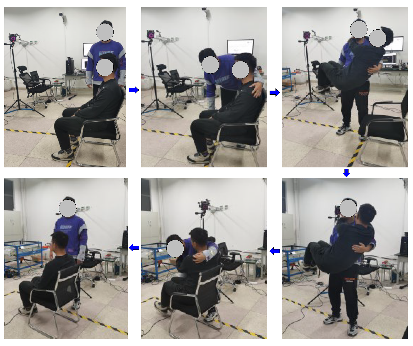
Figure 3.
Coordinate system of the pick-up action.

Figure 4.
Variation of the body angle.

Figure 5.
Minimum trajectory ranges of the markers on the nursed persons.

Figure 6.
Concept map of the robotic sling.

Figure 7.
The series-parallel transfer nursing robot.
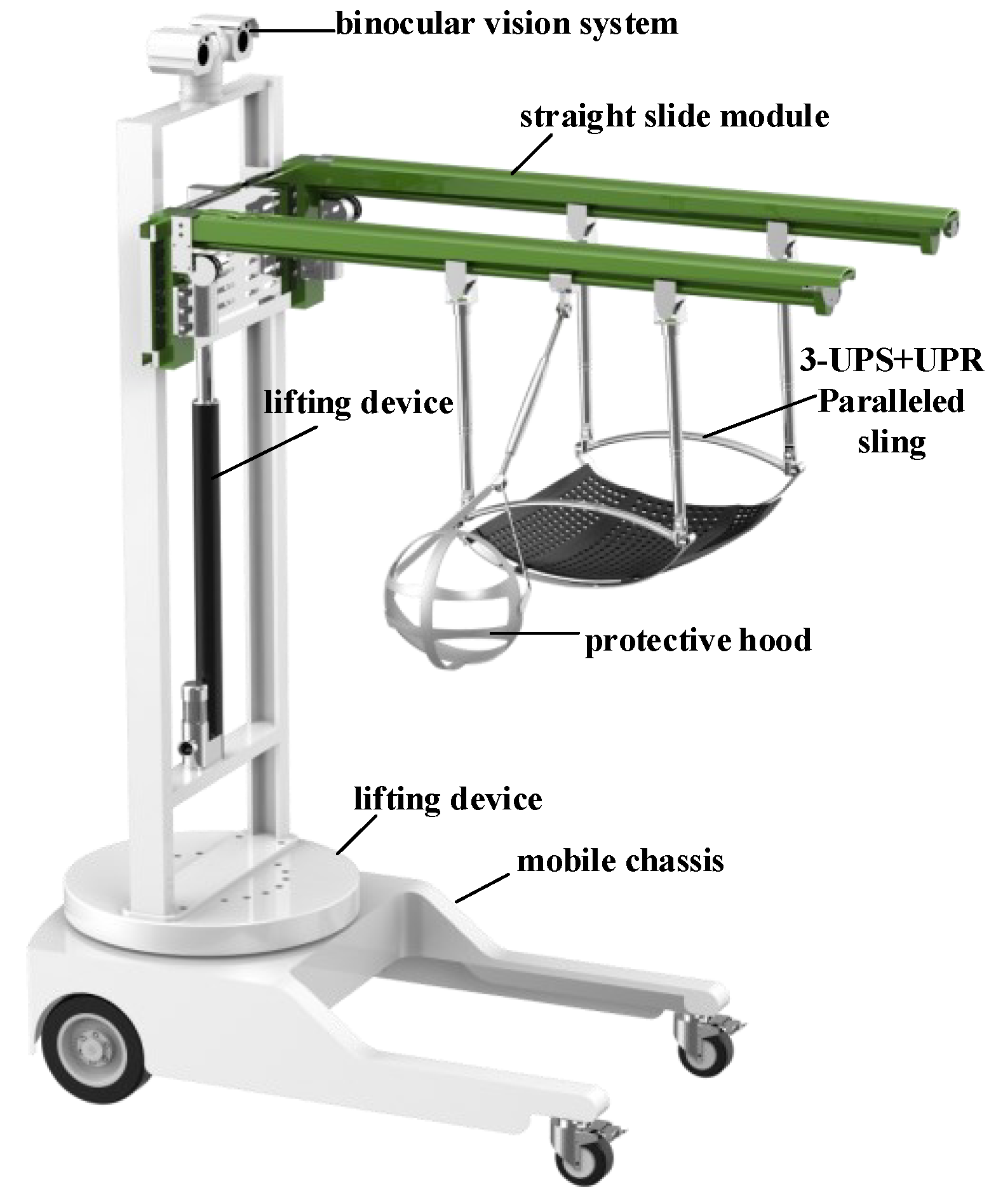
Figure 8.
The 3-UPS + UPR paralleled sling.

Figure 9.
The topological structure of the 3-UPS + UPR paralleled sling mechanism.

Figure 10.
The workspace of the 3-UPS + UPR paralleled mechanism.

Figure 11.
Simulated diagram of the workspace of the 3-UPS + UPR paralleled mechanism.

Figure 12.
Theoretical variation curve of the driving force.

Figure 13.
Simulated variation curve of the driving force.

Figure 14.
Transfer test on the robot. (a) starting transport (b) preparatory stage (c) Initial stage of transport (d) Medium-term transport (e) Post-transport (f) End of transport.
Figure 14.
Transfer test on the robot. (a) starting transport (b) preparatory stage (c) Initial stage of transport (d) Medium-term transport (e) Post-transport (f) End of transport.

Figure 15.
Contact pressure distribution on the backs of different test subjects.

Figure 16.
Comments of the nursed persons’ comfort degree in the test stages.


Table 1.
Information of the nursed persons.
| Height, mm | Weight, kg | Sex | Age | |
|---|---|---|---|---|
| Nursed person 1 | 1520 | 53 | Female | 23 |
| Nursed person 2 | 1650 | 70 | Male | 24 |
| Nursed person 3 | 1700 | 72 | Male | 24 |
| Nursed person 4 | 1750 | 78 | Male | 29 |
| Nursed person 5 | 1810 | 85 | Male | 35 |
Table 2.
Geometric and inertial parameters of the mechanism.
| Simulated Parameter | Value | Unit |
|---|---|---|
| L, l, z | 0.35, 0.30, 0.32 | m |
| ( = 1, 2, 3, 4) | 0.32 | m |
| , ( = 1,2,3,4) | 4.035, 1.524 | kg |
| diag [0.0801 0.0425 0.1225] | kg·m2 | |
| diag [0.0829 0.0639 0.0211] | kg·m2 | |
| [0 0 –120]T | N | |
| [0 50 0]T | N·m |
Table 3.
Information about the test subjects.
| Height, mm | Weight, kg | Sex | Age | |
|---|---|---|---|---|
| Nursed person 1 | 1550 | 60 | Male | 23 |
| Nursed person 2 | 1670 | 70 | Male | 24 |
| Nursed person 3 | 1710 | 73 | Male | 24 |
| Nursed person 4 | 1750 | 78 | Male | 29 |
| Nursed person 5 | 1800 | 85 | Male | 35 |
| Nursed person 6 | 1850 | 80 | Male | 26 |
| Nursed person 7 | 1700 | 56 | Female | 26 |
| Nursed person 8 | 1650 | 55 | Female | 25 |
| Nursed person 9 | 1780 | 78 | Male | 24 |
| Nursed person 10 | 1790 | 80 | Male | 25 |
Disclaimer/Publisher’s Note: The statements, opinions and data contained in all publications are solely those of the individual author(s) and contributor(s) and not of MDPI and/or the editor(s). MDPI and/or the editor(s) disclaim responsibility for any injury to people or property resulting from any ideas, methods, instructions or products referred to in the content. |
© 2023 by the authors. Licensee MDPI, Basel, Switzerland. This article is an open access article distributed under the terms and conditions of the Creative Commons Attribution (CC BY) license (https://creativecommons.org/licenses/by/4.0/).
Share and Cite
MDPI and ACS Style
Li, J.; Wang, C.; Deng, H. Hybrid Nursing Robot Based on Humanoid Pick-Up Action: Safe Transfers in Living Environments for Lower Limb Disabilities. Actuators 2023, 12, 438. https://doi.org/10.3390/act12120438
AMA Style
Li J, Wang C, Deng H. Hybrid Nursing Robot Based on Humanoid Pick-Up Action: Safe Transfers in Living Environments for Lower Limb Disabilities. Actuators. 2023; 12(12):438. https://doi.org/10.3390/act12120438
Chicago/Turabian StyleLi, Jiabao, Chengjun Wang, and Hailong Deng. 2023. "Hybrid Nursing Robot Based on Humanoid Pick-Up Action: Safe Transfers in Living Environments for Lower Limb Disabilities" Actuators 12, no. 12: 438. https://doi.org/10.3390/act12120438
Note that from the first issue of 2016, this journal uses article numbers instead of page numbers. See further details here.