Abstract
Through soft robotics, flexible structures confer an elevated degree of protection and safety in usage, as well as precision and reliability. Using theoretical models while combining different types of soft components opens a wide variety of possibilities for the development of new and better alternatives to rigid robots. Modeling and controlling soft robotic structures is still a challenge and is presented in different ways by the scientific community. The present scientific work aims to combine two of the most popular types of soft actuators, specifically shape memory alloy and pneumatic actuators. The purpose is to observe the interaction between individual entities and the resulting combined dynamics, highlighting the distinctive effects and influences observed in the combined system. An evaluation is conducted from a numerical simulation perspective in the MATLAB environment using representative mathematical models. The tests prove that a structure combining these particular actuators benefits from the advantages of both components and even compensates for individual downsides.
1. Introduction
In the context of permanently evolving robotics, the area of soft and flexible robots distinctly appears to be increasingly popular. The fundamental driving reason for every technological innovation is the necessity to offer people an easier, more comfortable life. In the current era of engineering, a significant portion of rapidly developing technology is, naturally, oriented toward people’s interactive needs, as researchers and engineers always keep in focus the social and economic impact of their developments. The healthcare sector is one of the few fields that combines technological advances with the diverse range of needs, from basic to complex, of patients and medical personnel to enable an environment where impressive medical procedures can be performed. Retrospectively, the medical field has received important help from the technology field through the adoption of tools and equipment capable of increasing the efficiency of medical staff, the speed of rehabilitation, and even professional at-home healthcare.
As described in [1], the integration of robots in medicine practice started with the neuro-surgical robot in the 1980s, leading to the voice-controlled endoscope in 2007 and the more recent da Vinci SP incision flexible arm and Monarch robot for bronchoscopy. In this manner, the development of medical robots uses a different approach, separating different types of robots and actuation for specific procedures or domains. Rigid robots are mainly used in heavy-wielding and mobility tasks, whereas medical procedures use flexible robots and structures. Increasing the safety of the operation of these devices led to the idea of different types of actuation, such as ones with reduced contact damage risk.
The need for small and powerful devices implies the need for specific types of actuation, including volume-reduced and high-precision robots and actuators. Some categories of soft actuators are electric and piezoelectric actuators [2], chemically and magnetically driven actuators [3], and pneumatic/ fluidic actuators [4], but considering the development speed of the field, new actuators continue to emerge.
As presented in [5], continuum robots have various medical applications classified by body area and actuation type. These robotic components (soft actuators) can enhance safety through their usage, but the control strategies necessitate the development of complex models and control structures. While mechanical and task-oriented approaches lead to fast development and implementation, even with many intermediary versions, the modeling area struggles to maintain mathematical representations’ simulation capabilities and accuracy.
Soft actuators include artificial muscles [6], sensing skin-imitating devices [7], and other flexible robots. The authors of [8] provided a detailed perspective on using flexible structures for actuation and sensing. An important subdivision of flexible robots is the soft robotics area and soft actuation technologies, which have been applied in developing rehabilitation devices, as presented in [9].
Performing actuations in soft robotics requires movement predictability, precision, and consistent performance. More precisely, the control structure driving the robotic soft actuator needs to be specifically designed based on a mathematical model for which classical and modern control strategies can provide predictable performance.
Most actuators in the literature are specialized, using basic actuation methods and simplified models (based mainly on physical design) to determine expected displacements. But while rigid robotics can combine electrical rotational joints, which provide angular precision, with pneumatic cylinders, which offer power and force stability, soft actuation can be used similarly, combining the benefits of both components.
Rigid–soft hybrids are one possibility of combining different actuations, using the rigid component to sustain the soft actuation or, as presented in [10], using a rigid structure to encapsulate the control of the soft robot. The resulting actuators and methods could provide more complex dynamics that enhance performance due to the use of both elements. Combining different types of soft actuation can also provide capabilities applicable in various domains or yield better outcomes. The components in the soft robotics class are fundamentally different from each other but are nevertheless compatible and interconnectable.
When considering the two types of soft actuation, one can define two types of combined soft structures: hybrid and mixed systems. Mixed structures use two or more different actuation methods and actuators in parallel, and the result is a sum of effects applied to a theoretical target point. The hybrid structure, on the other hand, represents a chain of interactions between the soft structures, with the output being the motion of the last segment.
The reduced number of mixed or hybrid soft actuators in the literature and the physical implementations or mathematical approaches used leave a widely unexplored research direction. This is a first step in simulating hybrid soft actuators and can be considered a starting point for future endeavors.
The idea of hybrid soft structures is a recent research concept, and exploring it could provide novel insights. The already realized studies regarding this subject are limited in number and only cover certain aspects. A first example can be found in [11], which utilizes parallel actuation of shape memory alloy (SMA) wires in a spring form and a pneumatic bladder. This forms an actuation system aimed at the rehabilitation of upper limb movements. The actuations are realized separately and are used for specific individual purposes. It represents a hybrid system but not a hybrid actuation.
In [12], the authors presented an approach similar to a mixed structure. A soft cylinder with intrinsic passive elastic proprieties is covered with a separately driven SMA short wires network. When a particular arrangement of wires is driven, the cylinder develops a specific bending motion. The elastic proprieties are used as a reshaping method, and the cylinder body also serves as an actuator interaction body. This approach confirms the current research direction as a potential actuation field with unexplored possibilities.
Performing actuations in soft robotics requires movement predictability, precision, and known performances. More precisely, the control structure driving the robotic soft actuator needs to be specifically designed based on the mathematical model. Most actuators illustrated in the literature are specialized, using the basic actuation method and the known model (based on physical design) to determine the outcome displacements. Mixed actuators and methods could provide more complex dynamics that combine the benefits of the individual elements.
A first step guiding toward the mentioned area can be a simple but concrete mathematical model compatibility, starting from the already created models and developing a methodology to combine and test the numerical interaction between the outcomes. In this manner, one soft actuator model gives the driving input to another soft instance, creating a deterministic outcome based on both serial actuator models.
To the authors’ knowledge, the ongoing research differs from the state of the art and does not replicate or test any previous approaches. The limited state of the art argues that the research direction is yet to be explored with a broad potential spectrum.
The novelty brought to the research field by the present work is an efficient and easy-to-handle manner of combining different soft actuation models proposed, which can describe complex soft dynamics, which is essential in designing hybrid actuators. The mentions regarding compatibility strategies and testing methods are of the same importance. One necessary and significant contribution resulting from the overall research is the usage of fundamentally different simulation strategies, proving that the mathematically represented soft structures are data-compatible, regardless of the testing method.
The chosen design uses SMA wires and a PneuNet structure to underline the potential of hybrid soft robots. A system with an SMA actuator is complicated to control precisely due to its complex electrical–thermal–mechanical characteristics. Depending on the temperature and the external load, the behavior varies, and vibrations may occur due to the wires’ elasticity. Therefore, SMA actuators must be controlled robustly in response to environmental changes, modeling errors, and vibration suppression. Also, considering hysteresis as a nonlinear element in the control system, the controllers should be able to handle both position and force control. The development of a simulation model can start with approaches based on experimental data [13].
Both SMA and PneuNet analytical models are considered in a hybrid architecture, which is implemented via simulation in a MATLAB framework. The experimental results show how the performance of the hybrid architecture surpasses the performance of individual components.
The following sections of the paper cover all the developments in hybrid architecture. The second section describes the development and testing strategies and the general connection of the elements, from physical inspiration to the simulated product. The third section covers the mathematical principles at the foundations of the separated actuators along with each integration method and results, covering the development from concept to data. The following section presents the interconnection of the actuators and the constraints and limitations of the resulting hybrid structure. The testing results are presented in Section 5, along with discussions for each case, followed by a final section containing conclusions and perspectives for the future.
2. Methodology
In the context described above, we propose a solution inspired by two essential actuation elements, air pressure and electrical power, for soft materials represented by the SMA wire and the pneumatic network (PneuNet) actuator. The proposed hybrid soft structure uses the dynamics of the SMA wire to drive a classical pneumatic network, combining the electro-thermal fast response of the first with the elastic proprieties of the second.
The PneuNet presents a shape-recovering elasticity propriety that allows the actuator to move in the initial position once the actuation is stopped. The volume is maintained constant by variation of length to diameter ratio from low temperature (blue shape) to high temperature (red shape). As represented in Figure 1, where is the SMA actuation displacement, the SMA liner displacement can be used to pull the extended silicon robot, a process similar to the string actuation used for the homogeneous silicon actuators.

Figure 1.
From SMA displacement to PneuNet bending connection.
The downside of the SMA thermal-driven behavior is its environmental dependency. Once the actuator is heated to the desired temperature, the cooling process depends on the environmental temperature, not on a controllable measure. On the other hand, the PneuNet has an internal shape recovery process due to its elastic properties and the resistive component included in the actuator body. In this manner, the pneumatic actuator performs a fast shape-recovery speed when the pressure actuation stops or, in the current case, when the pulling force starts to decrease.
Combining the fast and stable actuation of the SMA and the recovery proprieties of the PneuNet can output a fast actuation in both directions, resulting in a reliable actuator with speed, stability, and force performance.
A numerical simulation of the two separated actuations resulting in a hybrid structure is realized in the MATLAB environment to prove the hybrid actuator and the mentioned hypothesis. The resulting interconnection of the expected mathematical outcomes in a graphical representation can be found in Figure 2. A mathematical model is implemented for the SMA, and the force-resulting force motion is used as a negative pressure input. P is noted at different pressure inputs in the figure. The PneuNet is simulated in a soft robotics specialized toolbox, SoRoSim, using the force mentioned as input.
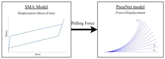
Figure 2.
From SMA numerical model towards the PneuNet simulation.
3. Modeling and Integration
The authors of [14] strongly argue about the complexity of the soft robotics model and the computational power required to accurately describe a soft behavior numerically, especially in online control structures. A simple solution is to design the control systems offline using an approximate representation of the desired actuator, which is also valid for mixed or hybrid soft structures.
The current section contains a comprehensive description of the physical principles based on the soft components and the practical integration process of the simulated models. The subsections also include the numerical representations of the physical proprieties and the numerical data used for the experimental simulations. The description provided is realized according to the mathematical model used in the numerical description.
3.1. SMA Preliminaries
The shape memory alloys are conductive metal composites, mostly found in nickel–titanium mixtures, which offer a smart-material propriety called the shape memory effect. This thermo-dynamical characteristic allows the alloy to shift from one molecular crystal structure to another when the temperature changes, reacting to the influence of the environment [15]. The alloy composition determines the range of shifting temperature and the state shapes resulting from preemptive ‘teaching’. The shape memory alloys are used in various actuators and can be driven by a wide range of actuation. As shapes, one of the most popular types of actuators is the linear wire, with the dynamics produced being a linear longitudinal displacement. For varying the actuating temperature, the conductive metal can react to chemical components, electromagnetic field changes, or even changes in the surrounding air temperature [16]. To change the internal temperature directly and obtain a faster response, an electrical current can power the wire, with the residual thermal energy activating the shape memory effect.
Considering the state of the art, different data-driven techniques were proposed to estimate the model parameters. According to the published results, the SMA model is a relation between the parameters and experimentally obtained stress, strain, and resistance data at various constant temperatures. For modeling the SMA wire, the shape memory effect and elastic and conductive properties are also considered. On the other hand, the temperature-shifting values are to be chosen according to the pre-training process and alloy composition (interdependent characteristics) [16].
3.2. SMA Model Implementation
Considering the complex behavior described above, it is clear that intertwined internal characteristics and structure variation as a response to external factors return a complex model description. For the current case exploration, the modeling considered will be the one proposed in [17]. The paper describes a coupled model of a generic shape memory alloy bar close to the SMA wire but with a detailed internal structure and material data.
The authors offer two approaches to determine the SMA internal manners, one having the stress-induced command returning the internal strain and one opposite, having the strain determining the stress. For the modeling necessary in the current development, the strain-driven model, the observable outcome is the stress of the metallic wire and the force present, both having similar forms.
The data found in the technical documents [18] was insufficient to have a complete model of the real SMA, so the available data was combined with various results from research papers, including [16,19,20].
Firstly, the material and environmental data must be specified with the critical consideration that the transitions between austenite and martensite and back determine the material propriety changes. Another aspect is related to the shape of the SMA and its size [21]. For the current implementation, Table 1 shows the material data and the phase separate proprieties.

Table 1.
Shape memory alloy numerical data.
The model is based on Gibbs energy, clearly representing the thermo-mechanical process inside the alloy and the material reactions. Computing the model requires the discretization of the SMA wire. The effect of the input is propagated along the wire, successively affecting the entire length of time.
The model uses the discretization of the SMA bat that keeps a consecutive step state change on the length. The surface area to volume ratio represents the physical dimensions and is included in the algorithm as the thermo-mechanical coupling.
The initial data and command signals need to be specified. Inspired by Equations (17), (24a,b), and (30) from [17], we can assume the initial values for force, the mean value of state-shifting temperatures , the differential mean temperature for coupled state temperatures w, and different prescribed strain shapes, used as a starting point for the current implementation. Also, the initial temperature is the room temperature specified in Table 1.
Each discreet segment of the wire is transitioning from one state to another depending on the strain value given as input. By transitioning, the internal variables of the wire are changing and need to be iteratively actualized, depending on the instantaneous phase.
Consider the following notations: is the state shifting length proportion, is the strain input, is the room temperature, and are the Young modulus at the shifting states, is the transfer strain, and is the thermal stress.
The internal temperature T shifting in time, containing all the material transformations, is given by (1), where k is the time moment for strain command. The stress is given in (2), and force F is given in (3).
Now, the phase shifting is to be analyzed by comparing the updated value of the force with the previous one. If the segment analyzed is transiting one state, the force is between the stress–temperature boundaries of the state. At this point, depending on the state, the stress is computed using (4) for martensite or (5) for austenite:
In both cases, the temperature is required to be recalculated using (6):
Depending on the phase-shifting state of the SMA, the next step is to compute the new shifting proportion with (7):
After the iterative phase-shifting process is realized, the force will be updated using (3). This process is to be applied for each discrete part of the considered wire, in this manner, the strain used as input is gradually applied to each one, and the transition is treated fluently and dynamically.
The modeled process is coupled, indicating that the stress–strain diagram suggests the type of alloy described, with the thermo-mechanical interaction having a critical impact. For the current approach, the stress–strain diagram is portrayed in Figure 3, in which the hysteresis gap describes the characteristic fount on a commercial SMA produced by DYNALLOY Inc., Irvine, CA, USA.
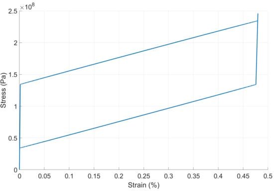
Figure 3.
Shape memory alloy stress–strain diagram.
3.3. PneuNet Functional Principle
The secondary actuator is a fast PneuNet pneumatic actuator, a succession of interconnected elastic silicon chambers. This type of actuator is prevalent in the literature and can be considered a standard choice for the current application. The proprieties of this actuator are explored in terms of design and material in [22].
From the actuation point of view, the PneuNet is driven by air pressure inflating the individual chambers and creating consecutive separating forces between chambers. The constraining layer at the base of the actuator has the decency to determine the shape of the motion.
The speed of the actuation and overall displacement are denoted by the shape, the elastic material used in the fabrication, and the wall thickness. Therefore, creating a universal interpretation in the form of a mathematical model or simulation environment is a challenge. In the literature, the modeling of the PneuNet is developed overwhelmingly in mechanical-oriented environments for the study of forces and elastic proprieties.
3.4. PneuNet Implementation
For the current approach, the actuator in the case is an 11-chamber PneuNet, as displayed in Figure 4. The model of the simulated body accurately represents the physical dimensions of the actuator, the overall elastic properties, and the motion restrictions on the base layer.
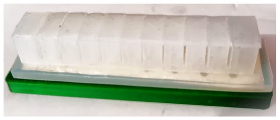
Figure 4.
Physical PneuNet used for modeling.
For development, the MATLAB R2023b toolbox SoRoSim is used due to its facilities for interconnecting soft, rigid, and combined structures. The only downside for the problem at stake is the non-homogeneity of the PneuNet; as the toolbox is designed for homogeneous robotic structures, the problem proved to be solvable in [23]. The material data presented and used for the integration are already modified to describe a non-homogeneous actuator, based on the same principle that the actuators used are similar.
The toolbox uses the interaction pop-up windows to create the composing elements of the PneuNet and the complete body, interconnections, and actuation. The elements have individual dimensions and material properties to reproduce the actual segment and, when connected, accurately reproduce the physical actuator.
Geometric Variable Strain (GVS) formalism is used for mathematical modeling to create similar support for rigid, soft, and mixed actuators. The modeling procedure is described in [24] and is resumed in the following paragraphs.
The technique used to map a shape reconfiguration of the robot uses the Cosserat roads description theory. This is known as micropolar elasticity, which incorporates the elastic behavior (twisting, bending, etc.) and defines the dynamics of a continuous segment. From this theory, the authors in [24] propose the interpretation of a continuous soft link as being from the initial configuration, or the Cosserat road base, () to the final configuration at the end of the road ().
Starting from a chain of consecutive segments composing a Cosserat rod, where is an element in the Special Euclidian group (SE(3)) or a curve for flexible structures and is represented by a homogeneous transformation containing a rotational matrix and a position vector in (8), where the body-frame at also includes joint constraints. A specific can be used to express the relation between a soft or rigid body segment and the previous chain of segments, as for a particular , from the Cosserat rod , a transformation has the form from (8):
To construct a chain of bodies describing consecutive spatial transformations, a product of exponentials (PoE) is used, based on the partial derivatives of space and time as in (9):
The strain twist body-frame can be further described as a component of the Euclidean space or in a vectorial representation in (10), where and are representations of angular strains, and represents the linear strain, with being the operations added to the Euclidean group:
Similarly, the velocity twist body-frame is described in the Euclidean space and in the vectorial representation in (11), where and are representations of angular velocity, and represents the linear velocity:
Using the equations in (9), the construction of a PoE can be done regardless of the rigidity of the analyzed segment. For the rigid body, the is similar to the body frame attached to i. In this manner, the product of exponentials describing the configuration of link i for the spatial frame can be developed using the Magnus expansion of at :
Therefore, the PoE results in the form of (14)
Starting from the product of exponentials, the kinematic chain of rigid, soft, or mixed links has the development described in [24] from Equation (8) to (19). The dynamic model covers the classical Lagrangian representation in (15), where is the vector of coordinates based on the considered strain. represents the mass matrix, is the Coriolis matrix, is the stiffness matrix, is the damping matrix, all of order, is the actuation matrix dependent on the number of actuators, and is the vector of generalized external forces. All matrices have specific representations as found in [24].
Concerning the computational implementation, some restrictions occur regarding the finite representations of components. Therefore, the product of exponentials implemented has the form of (16), considering the hth interval of a soft link i for which the value of the configuration is computed. The Magnus expansion also requires an approximation in the form detailed in the [24], along with the rest of the computational integration of the model.
These mathematically described components describe the kinematic and dynamic behavior of the complete elastic chain that can be created at the toolbox level. Working with the SoRoSim required the abstract definition of the individual links and their particular proprieties to define a complete linkage.
When the link is created, the model defines a chain of interaction between the consecutive geometric variables, describing the possible deformation in the form of linear and twist motion. As the discretization defines the motion model precision, the created links must reflect the deformation generated or applied during actuation. In the physical actuation, as mentioned in the previous subsection, the chambers’ interaction creates the pushing force, therefore the segments have separate effects.
For the current PneuNet, in the toolbox, three different links representing the principal types of segments are created:
- Ending link: representing the first and last chamber, with larger chambers and least powerful deformations;
- Chamber link: representing the intermediary chambers, which cause the deformation and the shape restoration;
- Channel link: representing the small segments interconnecting the other links, encapsulating the majority of the deformation.
The three link types are combined in a structure of 21 links, each keeping the material proprieties. The linkage structure also determines the links’ interaction and actuation possibilities. The toolbox’s default actuation type is string actuation. Although the PneuNet is generally actuated pneumatically, with pressurized air, a capability of the toolbox already proven possible in [25], the default string actuation accurately represents the SMA actuation.
The PneuNet propriety on focus is the shape recovery characteristic of elastic material. For the effect of the propriety to reach maximum potency, the pulling force outputted by the SMA model must be uniformly distributed along the actuated body. This is achieved using a distributed actuator (one for each link) with equal pulling force amplitude applied in the same manner as the air pressure [25].
The physical data used in the SoRoSim toolbox to describe PneuNet can be found in Table 2. The data describes each segment by the exterior dimensions, and the material data is already modified to represent the non-homogeneous elastic behavior as described in [25].

Table 2.
Soft robot physical dimensions and material characteristics.
Another critical aspect of the PneuNet linkage model is the presence of gravitational force. As the expected dynamic displacement evolves on the XOZ plane, or around the Y-axis, in the form of a rising on the Z-axis, the gravitational force is oriented in the negative Y direction. The motion of the PneuNet aims to be antagonistic to the gravitational pull, amplifying the shape recovery speed. Figure 5 presents the spatial representation of the PneuNet linkage created. The gravitational force is marked by the black arrow pointing in the negative Z-axis direction.

Figure 5.
Schematic PneuNet resulting from modeling.
The actuation functions used as input are provided to the simulation part of the toolbox as mathematical time-dependent expressions. The actuator’s initial condition must also be specified. The default posture is used in all of the following simulations, with no previous displacement on any robot link. The integration resulting linkage has the dimensional representation shown in Figure 6, with the physical constraint layers on the upper side.
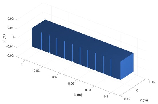
Figure 6.
PneuNet integrated body in default configuration.
The validity of the integrated model is given by the existing models found in the literature in the form of the displacement shown as the final posture and Z and X-axis time-displacement graphics, as the PneuNet was realized with the data provided in the research mentioned. The functions used for testing are a constant step function and a sigmoidal evolution, both with the same maximum value, as proven in [25].
4. Models Interconnection and Testing
The mathematical models of both actuators require and return specific data based on the modeling approach but are not necessarily simulation-compatible. The present section covers the procedures needed to convert the SMA model output, represented by force–time variation, into an input compatible with the PnueNet integration, represented by air pressure, in the toolbox. As mentioned above, the driving data used in the dynamic simulation of the PneuNet is a pulling force applied equivalently on each segment of the actuator.
The data obtained from the SMA model are a numerical representation of the force variation in time, being a deterministic result of a given temperature variation. The resulting force evolution in time does not respect a simple characteristic; it can be a succession of complex shapes united by discontinuity points. An example is depicted in Figure 7, showing a force output used for the first experiment.
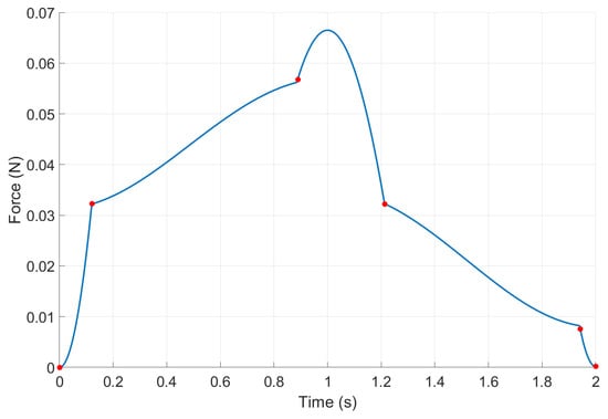
Figure 7.
Example of SMA model output.
On the other hand, the dynamic simulation in the SoRoSim toolbox requires a time-dependent solvable shape to interpret and drive the PneuNet. Considering this, several procedures are required to create numerical compatibility. Firstly, the SMA resulting shape must be separated into continuum intervals using the discontinuity points for discrimination. To increase the precision, the discontinuity points are determined using the second-order gradient for the evolution. In this manner, points are numerically determined based on the evolution, not approximated.
Each interval, containing numerically continuous partial evolution from the complete force, needs to be approximated using polynomial characteristics with a certain precision. The resulting time-dependent functions approximating the entire evolution of the SMA model force are compatible with the SoRoSim dynamic simulation input.
A critical aspect of the procedure is that a different simulation is realized for each approximated force interval. The dynamic simulation requires an initial condition for the geometric strain for each interval. The condition is the PneuNet state at the end of the previous simulation. In the case of the first interval, the initial condition is the default geometric strain state.
5. Results
This section covers the dynamics returned by the composed topology described above and the modeling principles presented, and it analyzes the final shape and the movement evolution. The expected displacement is shown distinctively in planar evolution (on the XOZ plane) and on the principle axis. It is important to note that the simulated experiments are realized in an open loop, focusing on the usefulness of the combined structure’s effect rather than on a controlled outcome.
Firstly, we need to analyze the effect of the SMA output shown in Figure 7 of the modeled PneuNet. As observed, the evolution presents five continuum intervals, offering a rapid variation over a 2 s period, which, according to [25], can be considered a shock actuation, therefore resulting in oscillatory potential behavior. The resulting outcomes for the described simulated experiment are shown in Figure 8.
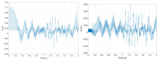
Figure 8.
PneuNet displacement on a rapid driving force (X—left; Z—right).
The oscillatory behavior of the actuated PneuNes is a simple and natural response of the elastic body to a rapidly increasing actuation force. It is a consequence that further proves the accuracy of the model. The physical reaction to a sudden pressure input in the pneumatic chambers is determining the fast contact interaction.
The compatibility forces and dynamics need to be ensured in the measurable environment provided by the PneuNet integration. The initial approaches correlating the inputs and outcomes for the model in a compatible manner were flawed but even more necessary in the development road, returning useful information about the compatibility status.
One possibility to reduce the shock effect is to expand the actuation over a more significant period, giving a more extended actuation period for each continuum interval. The following experiment uses the exact strain actuation of the SMA model but extends over a longer period, from 2 s to 20 s as in Figure 9. The figure below depicts the strain input on the alloy model and the force outputted to be used as PneuNet’s driving force.
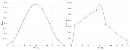
Figure 9.
SMA signals: Slower strain command (left) and outputted force (right).
As proven in [25], the expected behavior is an evolution with minimum oscillations, avoiding elastic shock–vibrational proprieties. A consequence of the extended intervals is a slower axial evolution, returning a more complex motion. In addition, the actuation returns a stable dynamic around the 10 s moment as a response to a negative oscillatory evolution by increasing the force. It is clear that the SMA response is directly reactive to the SMA outputted force and contains the specific PneuNet proprieties. The resulting displacements on the axis are displayed in Figure 10.
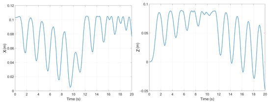
Figure 10.
PneuNet displacement on a slower driving force (X—left; Z—right).
Another aspect is represented by the observable fast response, presented by the experiments in Figure 10, where the Z-axis displacement has a constant initial increase, similar to an S-shaped function. The PneuNet outcome is an elastically damped response to the first interval (Figure 9 Right), resulting in a combined effect of the soft hybrid actuator.
Another experiment is realized with a strain input at half amplitude, returning a continuum pulling force. As displayed in Figure 11, the force evolution presents only two discontinuity points necessary for three interval approximations. Still, more importantly, it describes a steady force increase but at half the amplitude.
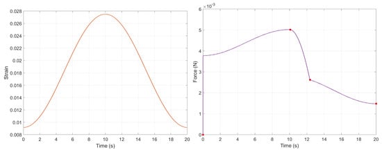
Figure 11.
SMA signals: Wider strain command (left) and outputted force (right).
By comparing with the experiments described in [25], the evolution on the first interval is expected to be also oscillatory; the time given for the force to reach a specific value, after which a slower variation occurs, is almost instantaneous. Although this can cause an unwanted oscillation, the effect should be damped by the slow and steady increase over time (over 10 s) before the start of the decreasing ramp.
On the second interval, the force is quickly decreasing, and considering also the gravitational pull on the PneuNet, it is expected to perform an amplified fall-like behavior. As the fall occurs, the final force’s level will rise after a decrease below the force’s resulting value. For the last interval, the displacement is expected to be stabilize at a particular position, oscillating around it. The results are observable in Figure 12.
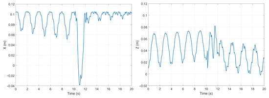
Figure 12.
PneuNet displacement on for previous driving force (X-left and Z-right).
The displayed images confirm the supposition by the displacements presented on both axis evolutions. It is important to note that the force amplitude driving the PneuNet decreased compared to the previous experiments. The consequence was the decreased Z displacement and damping of the oscillations.
In the current experiment, the relation between the SMA-generated force directly influencing the PneuNet behavior and the oscillatory dynamics produced by the elastic characteristic. Each force interval described above generates a specific outcome, combining the actuation speed of the SMA and the PneuNet shape recovery propriety.
Corroborating the experiments described above, important ideas can be extracted. One essential aspect is the generated actuation force from the SMA, presented as the PneuNet driving signal acting antagonistically to the elastic shape recovery propriety and towards a damped, smoothed displacement. In the presented experiments, we validated that the hybrid architecture benefits from a superposition behavior regarding the advantages of each component. This result allows for future development in both modeling and practical applications.
6. Conclusions and Future Work
The present work proves that soft robotics is at the beginning of the exploratory phase and still has vast areas to uncover and understand. The proposed architecture shows the potential of hybrid soft actuation in the performance enhancement of the individual components. The concept proves that more complex structures could be tested and verified and that the numerical representations of soft components are inter-connectable using slight compatibility regarding scales and approximations.
In the detailed analysis, the hybrid architecture uses mathematical models that are approximations of ideal physical components. One critical remark is that the numerical data (namely the force signal) transferred from one actuator to the other are suitable for polynomial approximation. Based on this, the resulting dynamical behavior shows enhanced performance compared to individual components’ performance.
The experimental results highlight that the behavior of the force generated by the SMA wire model can drive the PneuNet integrated model. The resulting displacements contain a combined influence of the component proprieties. The elastic characteristics dampen the SMA wire’s fast responses, while the oscillatory dynamic of the PneuNet is reduced by the constant force maintained by the SMA.
The presented procedure proves functional for the test case but can be extrapolated and used for different hybrid structures. The only required consideration is the conversion between the physical data, creating physical quantity compatibility and, if necessary, converting the amplitude from one actuator to the other, representing a transfer element in the real system.
Regarding future work, one of the main goals will be to integrate elements from fluid mechanics and thermodynamics in a hybrid architecture. Also, sensing elements can be used to widen the application areas. The resulting schemes would allow for the simulation of multiple case studies with potential physical implementation. This can provide novel actuation types, hybrid structures, and more complex testing scenarios.
Last, but not least, the required work to firmly conclude the hybrid performance is to physically implement and test the simulated structure while measuring and evaluating data and outcomes. Although the real testing plant could be influenced by material imperfections and various surrounding thermal or positioning conditions, the continuous phenomena at the material level of the SMA and PneuNet, the effect discretized in modeling, could prove to be a more fluent combined behavior.
Author Contributions
Conceptualization, both; methodology, both; software and validation, F.-A.B.; formal analysis, A.B.; writing—original draft preparation, F.-A.B.; writing—review and editing, both; supervision A.B. All authors have read and agreed to the published version of the manuscript.
Funding
This research received no external funding.
Data Availability Statement
The data supporting this study’s findings are available from the first author or corresponding author upon reasonable request.
Conflicts of Interest
The authors declare no conflicts of interest.
References
- Troccaz, J.; Dagnino, G.; Yang, G.Z. Frontiers of medical robotics: From concept to systems to clinical translation. Annu. Rev. Biomed. Eng. 2019, 21, 193–218. [Google Scholar] [CrossRef] [PubMed]
- Kheirikhah, M.M.; Rabiee, S.; Edalat, M.E. A review of shape memory alloy actuators in robotics. In Proceedings of the RoboCup 2010: Robot Soccer World Cup XIV 14, Singapore, 25 June 2011; pp. 206–217. [Google Scholar]
- El-Atab, N.; Mishra, R.B.; Al-Modaf, F.; Joharji, L.; Alsharif, A.A.; Alamoudi, H.; Diaz, M.; Qaiser, N.; Hussain, M.M. Soft actuators for soft robotic applications: A review. Adv. Intell. Syst. 2020, 2, 2000128. [Google Scholar] [CrossRef]
- Xavier, M.S.; Fleming, A.J.; Yong, Y.K. Finite element modeling of soft fluidic actuators: Overview and recent developments. Adv. Intell. Syst. 2021, 3, 2000187. [Google Scholar] [CrossRef]
- da Veiga, T.; Chandler, J.H.; Lloyd, P.; Pittiglio, G.; Wilkinson, N.J.; Hoshiar, A.K.; Harris, R.A.; Valdastri, P. Challenges of continuum robots in clinical context: A review. Prog. Biomed. Eng. 2020, 2, 032003. [Google Scholar] [CrossRef]
- Park, Y.L.; Santos, J.; Galloway, K.G.; Goldfield, E.C.; Wood, R.J. A soft wearable robotic device for active knee motions using flat pneumatic artificial muscles. In Proceedings of the 2014 IEEE International Conference on Robotics and Automation (ICRA), Hong Kong, China, 31 May–7 June 2014; pp. 4805–4810. [Google Scholar]
- Tabasi, S.F.; Banihashemi, S. Design and mechanism of building responsive skins: State-of-the-art and systematic analysis. Front. Archit. Res. 2022, 11, 1151–1176. [Google Scholar] [CrossRef]
- Heng, W.; Solomon, S.; Gao, W. Flexible electronics and devices as human–machine interfaces for medical robotics. Adv. Mater. 2022, 34, 2107902. [Google Scholar] [CrossRef] [PubMed]
- Pan, M.; Yuan, C.; Liang, X.; Dong, T.; Liu, T.; Zhang, J.; Zou, J.; Yang, H.; Bowen, C. Soft actuators and robotic devices for rehabilitation and assistance. Adv. Intell. Syst. 2022, 4, 2100140. [Google Scholar] [CrossRef]
- Stokes, A.A.; Shepherd, R.F.; Morin, S.A.; Ilievski, F.; Whitesides, G.M. A hybrid combining hard and soft robots. Soft Robot. 2014, 1, 70–74. [Google Scholar] [CrossRef]
- Golgouneh, A.; Beaudette, E.; Woelfle, H.; Li, B.; Subash, N.; Redhouse, A.J.; Jones, M.; Martin, T.; Lobo, M.A.; Holschuh, B.; et al. Design of a hybrid SMA-pneumatic based wearable upper limb exoskeleton. In Proceedings of the 2021 ACM International Symposium on Wearable Computers, Virtual, 21–26 September 2021; pp. 179–183. [Google Scholar]
- Allen, E.A.; Swensen, J.P. Design of a Highly-Maneuverable Pneumatic Soft Actuator Driven by Intrinsic SMA Coils (PneuSMA Actuator). In Proceedings of the 2020 IEEE/RSJ International Conference on Intelligent Robots and Systems (IROS), Las Vegas, NV, USA, 24 October–24 January 2020; pp. 8667–8672. [Google Scholar]
- Shibly, H.; Söffker, D. Mathematical models of shape memory alloy behavior for online and fast prediction of the hysteretic behavior. Nonlinear Dyn. 2010, 62, 53–66. [Google Scholar] [CrossRef]
- Walker, J.; Zidek, T.; Harbel, C.; Yoon, S.; Strickland, F.S.; Kumar, S.; Shin, M. Soft robotics: A review of recent developments of pneumatic soft actuators. Actuators 2020, 9, 3. [Google Scholar] [CrossRef]
- Brojan, M.; Bombač, D.; Kosel, F.; Videnič, T. Shape memory alloys in medicine Materiali z oblikovnim spominom v medicini. RMZ-Mater. Geoenviron. 2008, 55, 173–189. [Google Scholar]
- Crews, J.H.; Smith, R.C.; Pender, K.M.; Hannen, J.C.; Buckner, G.D. Data-driven techniques to estimate parameters in the homogenized energy model for shape memory alloys. J. Intell. Mater. Syst. Struct. 2012, 23, 1897–1920. [Google Scholar] [CrossRef]
- Zhuo, M. Timescale competition dictates thermo-mechanical responses of NiTi shape memory alloy bars. Int. J. Solids Struct. 2020, 193, 601–617. [Google Scholar] [CrossRef]
- DYNALLOY Inc. Technical Characteristics of FLEXINOL® Actuator Wires. 2023. Available online: https://www.dynalloy.com/pdfs/TCF1140.pdf (accessed on 3 October 2023).
- Bengisu, M.; Ferrara, M. Materials That Move: Smart Materials, Intelligent Design; Springer: Cham, Switzerland, 2018. [Google Scholar]
- Abdullah, E.J.; Soriano, J.; Fernández de Bastida Garrido, I.; Abdul Majid, D.L. Accurate position control of shape memory alloy actuation using displacement feedback and self-sensing system. Microsyst. Technol. 2021, 27, 2553–2566. [Google Scholar] [CrossRef]
- Kim, M.S.; Heo, J.K.; Rodrigue, H.; Lee, H.T.; Pané, S.; Han, M.W.; Ahn, S.H. Shape memory alloy (SMA) actuators: The role of material, form, and scaling effects. Adv. Mater. 2023, 35, 2208517. [Google Scholar] [CrossRef] [PubMed]
- Gariya, N.; Kumar, P. A comparison of plane, slow pneu-net, and fast pneu-net designs of soft pneumatic actuators based on bending behavior. Mater. Today Proc. 2022, 65, 3799–3805. [Google Scholar] [CrossRef]
- Braşoveanu, F.A. Soft Robotics Modeling and Simulation. In Proceedings of the IFToMM International Symposium on Science of Mechanisms and Machines (SYROM), Iasi, Romania, 17–18 November 2022; Springer: Cham, Switzerland, 2022; pp. 371–380. [Google Scholar]
- Mathew, A.T.; Hmida, I.M.B.; Armanini, C.; Boyer, F.; Renda, F. Sorosim: A Matlab toolbox for hybrid rigid-soft robots based on the geometric variable-strain approach. IEEE Robot. Autom. Mag. 2022, 30, 106–122. [Google Scholar] [CrossRef]
- Braşoveanu, F.A.; Burlacu, A. Soft Robotics: A Numerical Evaluation of Model-Based PneuNet Simulation. In Proceedings of the International Symposium on Measurements and Control in Robotics (ISMCR), Iasi, Romania, 21–22 September 2023; Springer: Cham, Switzerland, 2023. [Google Scholar]
Disclaimer/Publisher’s Note: The statements, opinions and data contained in all publications are solely those of the individual author(s) and contributor(s) and not of MDPI and/or the editor(s). MDPI and/or the editor(s) disclaim responsibility for any injury to people or property resulting from any ideas, methods, instructions or products referred to in the content. |
© 2024 by the authors. Licensee MDPI, Basel, Switzerland. This article is an open access article distributed under the terms and conditions of the Creative Commons Attribution (CC BY) license (https://creativecommons.org/licenses/by/4.0/).