
Suspension Flux Internal Model Control of Single-Winding Bearingless Flux-Switching Permanent Magnet Motor


Abstract
:1. Introduction
2. Topology and Mathematical Model of BFSPMM
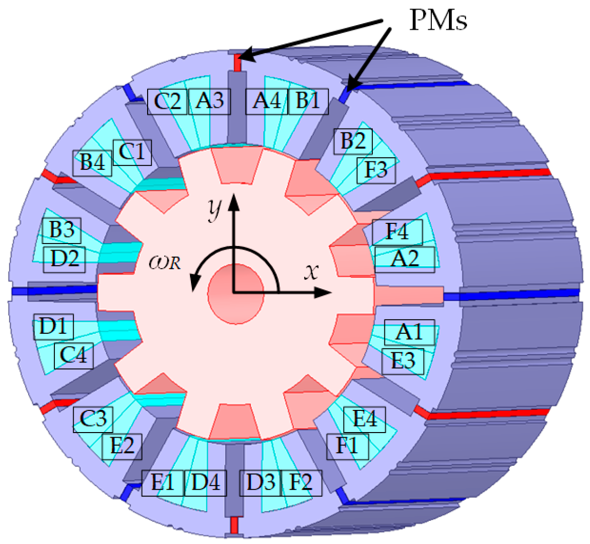
2.1. Topology
2.2. Rotor Dynamics Model of BFSPMM
2.3. Suspension Force-Flux Mathematical Model
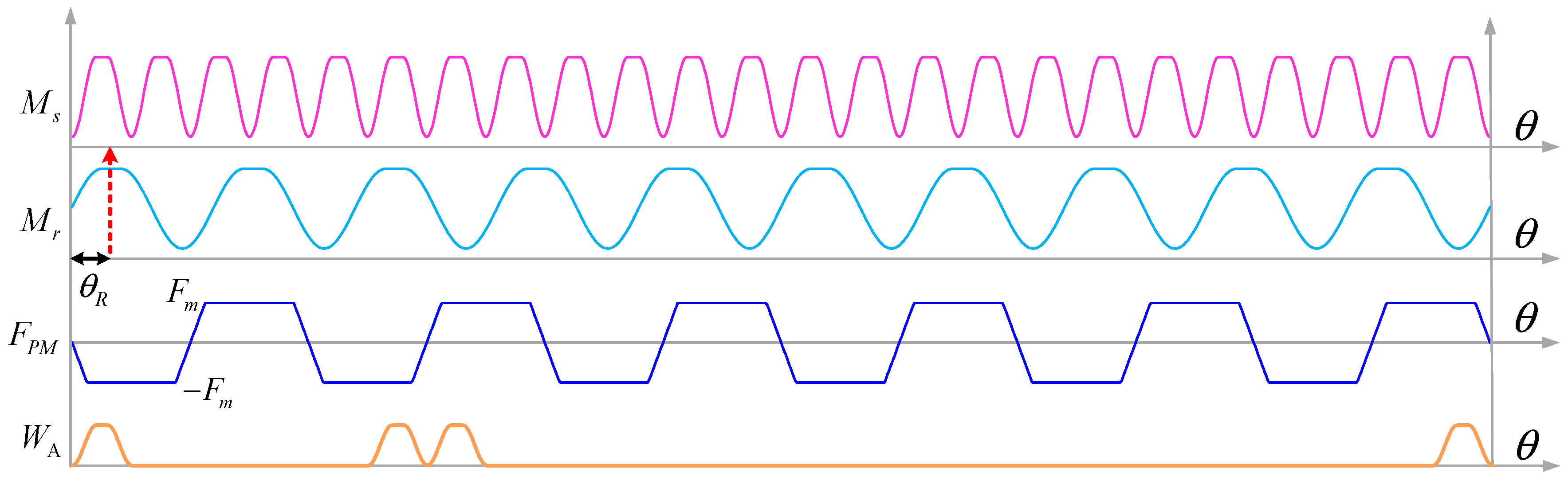
2.3.1. Expression of No-Load PM Flux
2.3.2. Inductance Expression
2.3.3. Mathematical Model of Suspension Flux
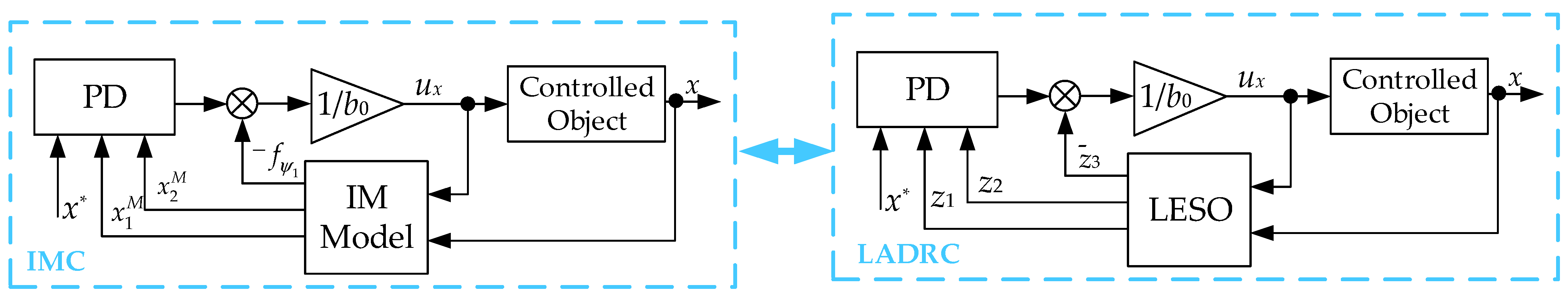
3. Suspension Flux Internal Model Control Strategy
3.1. Suspension Flux-Dynamics Internal Model of BFSPMM
3.2. Feedback Linearization of Auxiliary Function
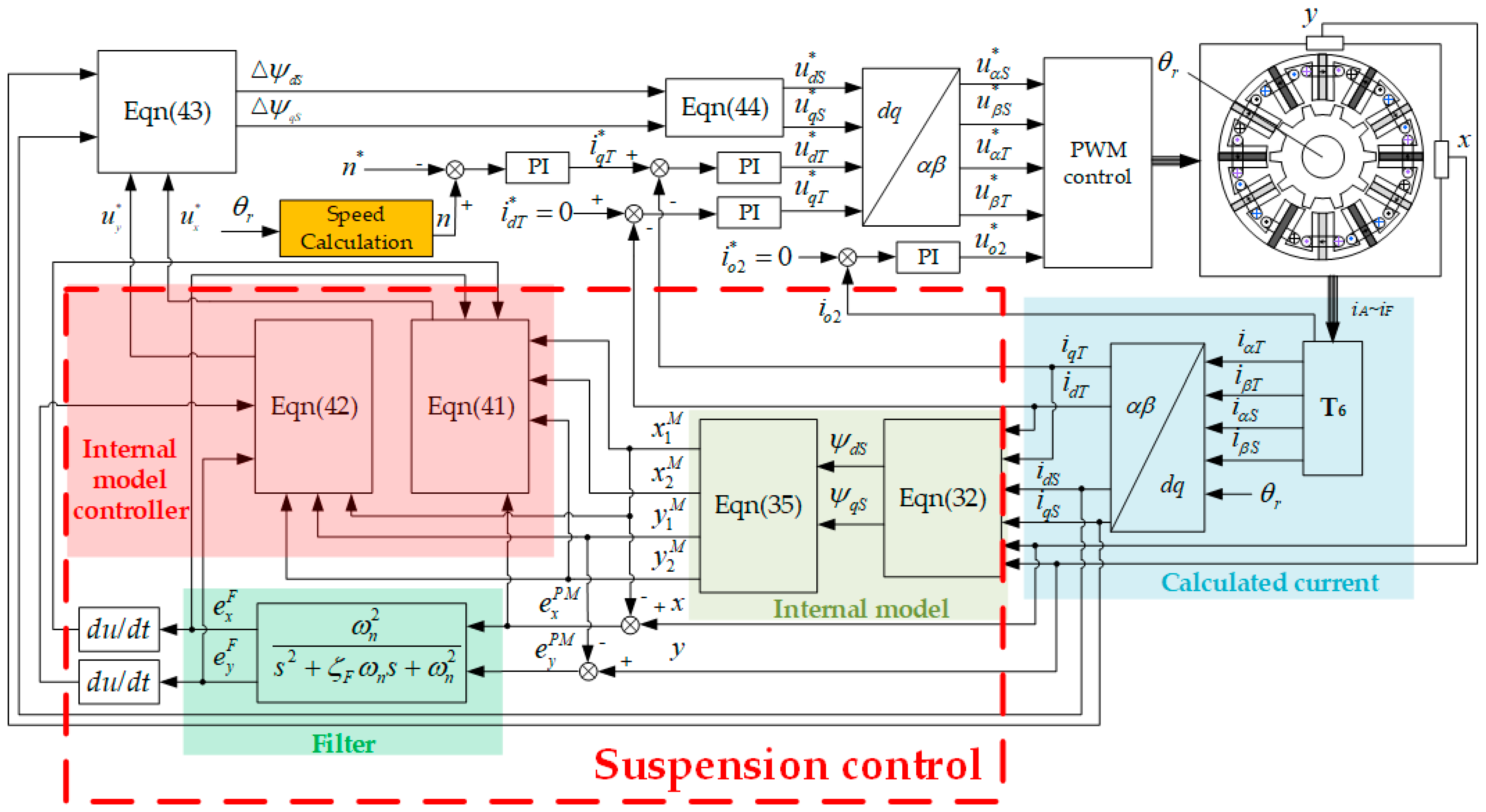
3.3. Control Block Diagram
4. Verification
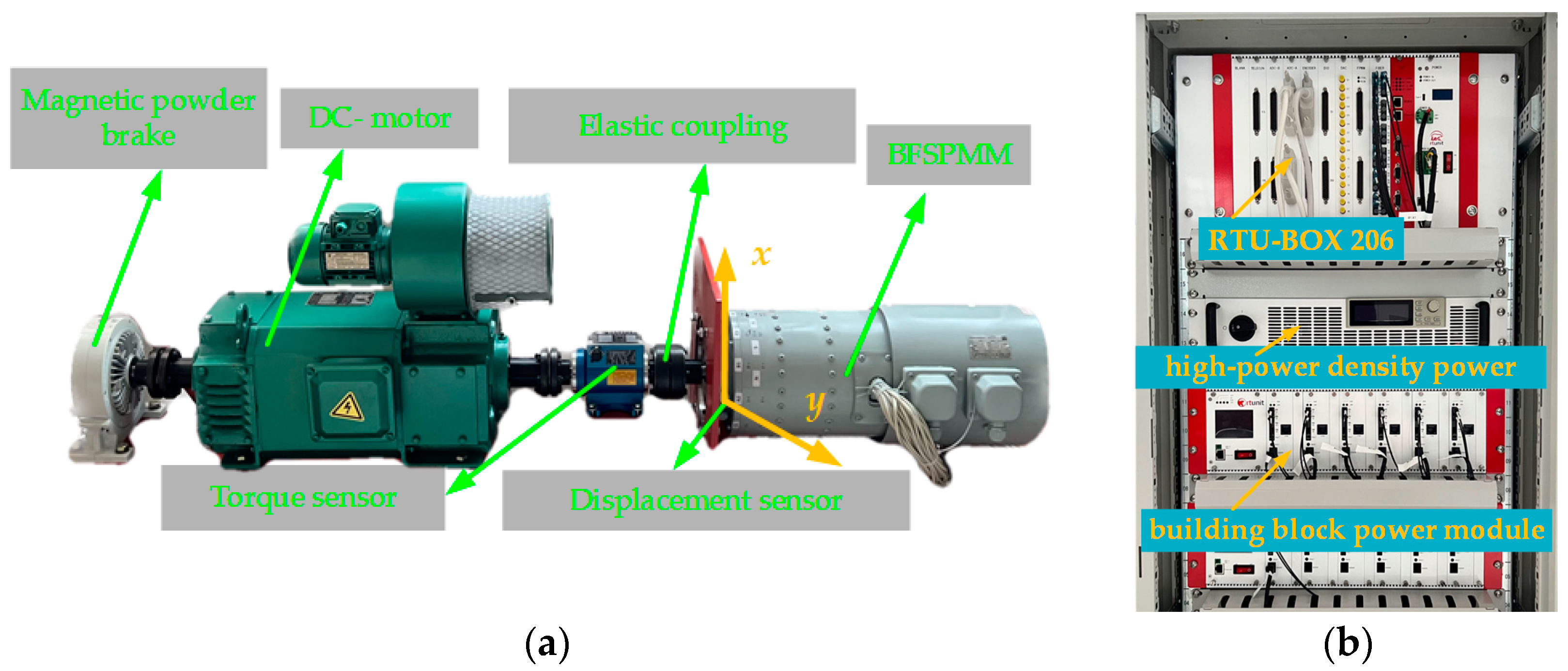
4.1. Test Platform
4.2. Simulation Results
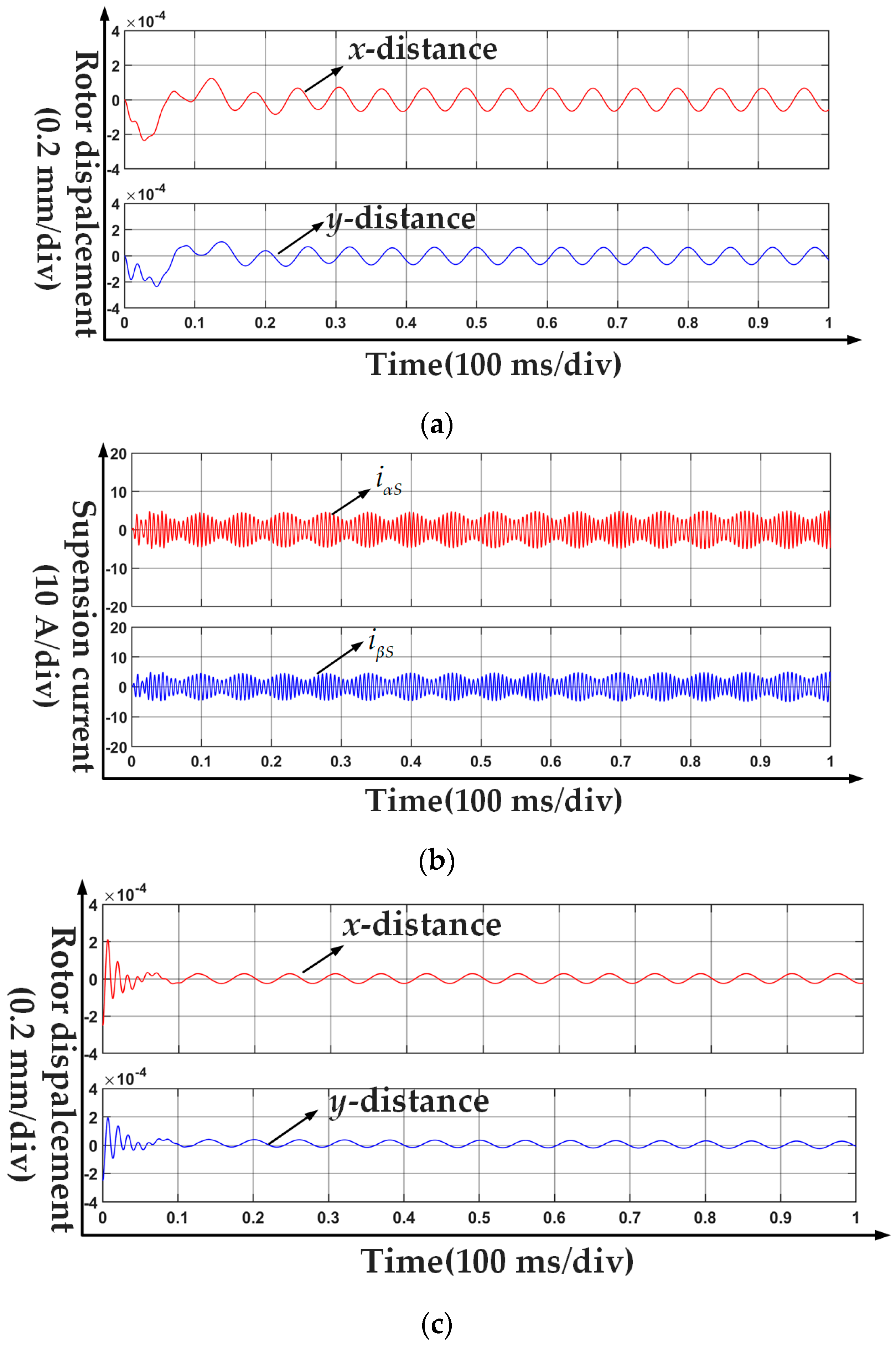
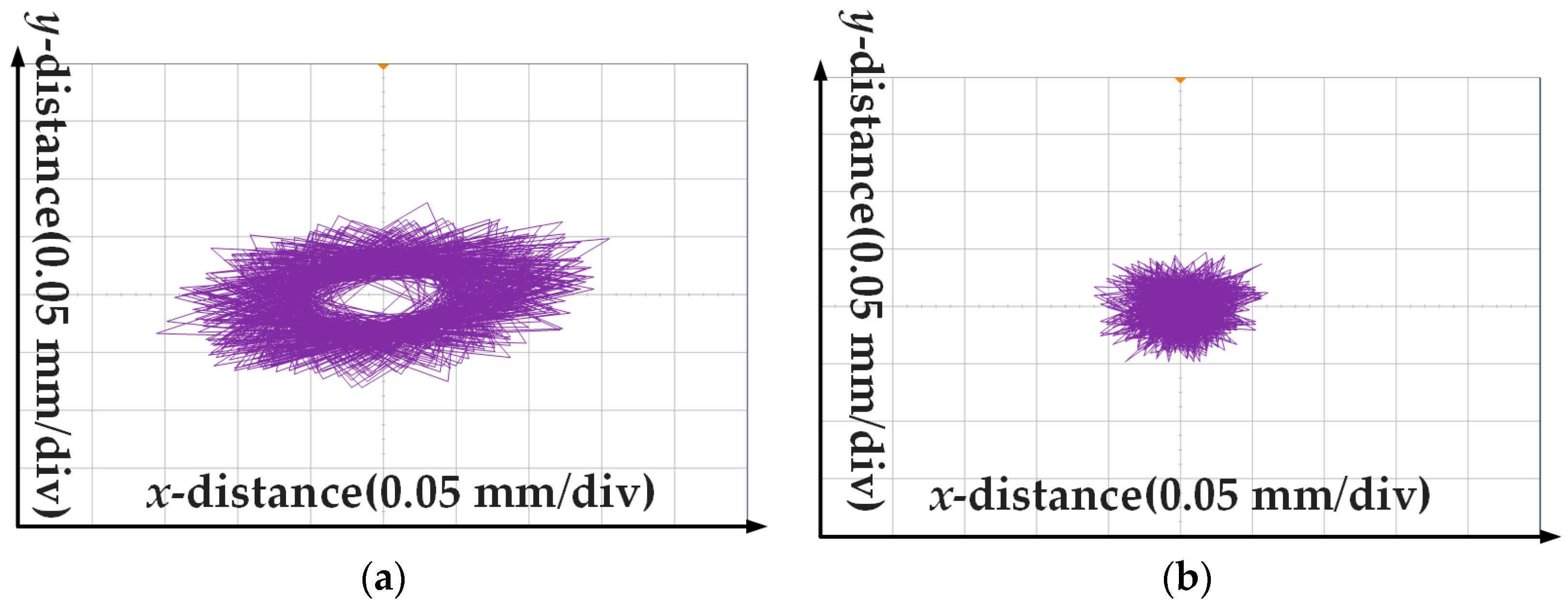
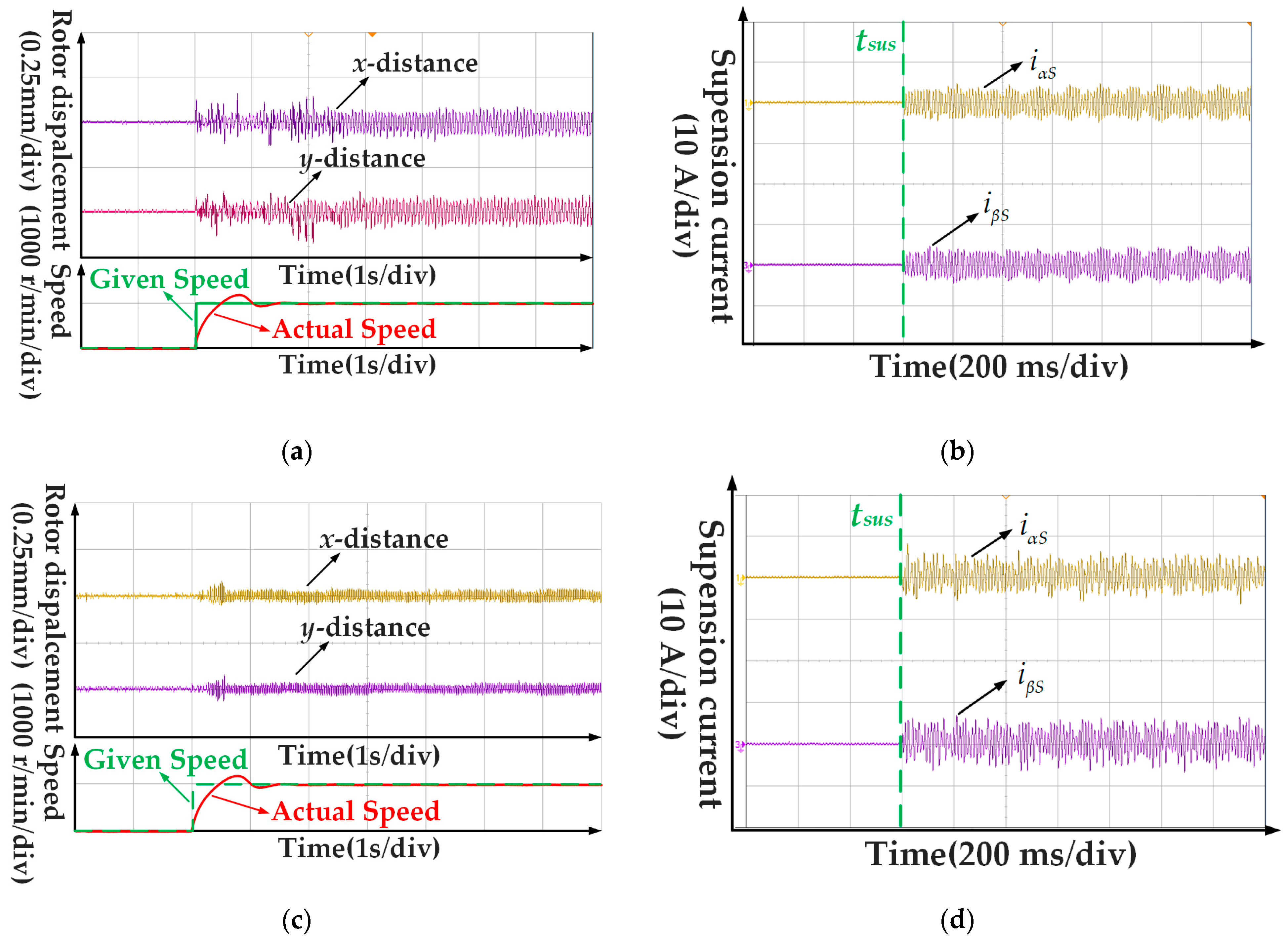
4.3. Steady-State Experiment
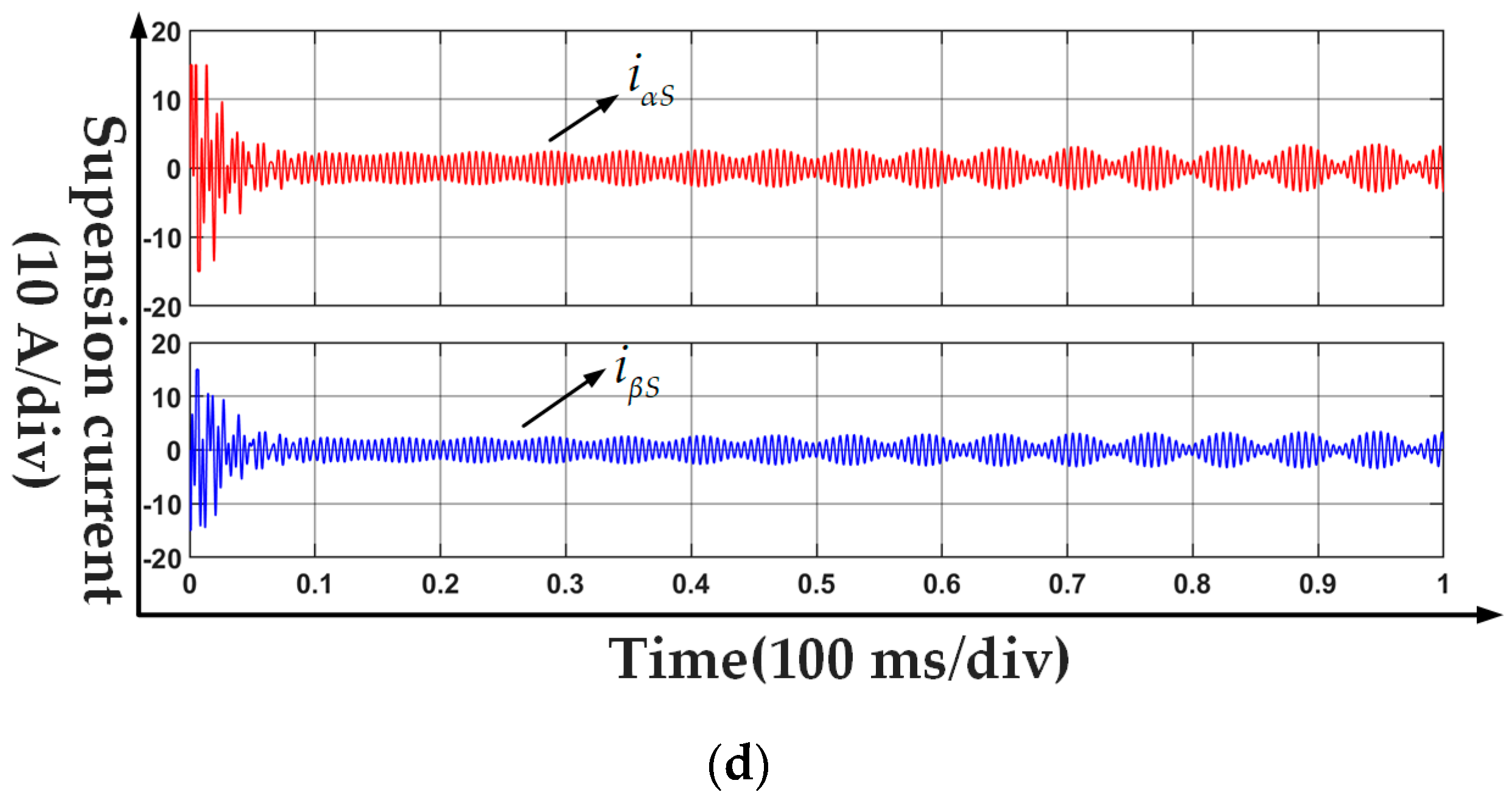
4.4. Dynamic-State Experiment
5. Discussion
6. Conclusions
- (1)
- The high-performance decoupling control of a single-winding BFSPMM is realized, and the radial displacement of the rotor is always suspended with a small radial displacement in the geometric center axis.
- (2)
- Compared with the traditional PID control, the proposed method has better steady-state performance, and the maximum radial displacement ripple of the rotor is reduced by 53%, which effectively improves the antijamming and robustness of the system.
- (3)
- Compared with the traditional PID control, the proposed method has better dynamic-state performance and reduces the radial vibration of the rotor in the process of speed regulation under the load-speed step condition.
Author Contributions
Funding
Data Availability Statement
Conflicts of Interest
References
- Chen, J.; Zhu, J.; Severson, E.L. Review of Bearingless Motor Technology for Significant Power Applications. IEEE Trans. Ind. Appl. 2020, 56, 1377–1388. [Google Scholar] [CrossRef]
- Sun, X.; Chen, L.; Yang, Z. Overview of Bearingless Permanent-Magnet Synchronous Motors. IEEE Trans. Ind. Electron. 2012, 60, 5528–5538. [Google Scholar] [CrossRef]
- Asama, J. Development of Slotless Single-Drive Bearingless Permanent Magnet Motor With Aerostatic Bearings for High-Speed Applications. IEEE Trans. Ind. Appl. 2023, 59, 4076–4082. [Google Scholar] [CrossRef]
- Sala, G.; Valente, G.; Di Nardo, M.; Degano, M.; Zanchetta, P.; Gerada, C. Power-Sharing Control in Bearingless Multi-Sector and Multi-Three-Phase Permanent Magnet Machines. IEEE Trans. Ind. Electron. 2021, 68, 9070–9080. [Google Scholar] [CrossRef]
- Khamitov, A.; Gruber, W.; Bramerdorfer, G.; Severson, E.L. Comparison of Combined Winding Strategies for Radial Nonsalient Bearingless Machines. IEEE Trans. Ind. Appl. 2021, 57, 6856–6869. [Google Scholar] [CrossRef]
- Chen, Y.; Wu, X.; Zhou, Y. Fault-Tolerant Operation Control Strategy for Combined Winding Bearingless Flux-Switching Permanent Magnet Motor Drive System with One Opened Phase. IEEE Trans. Energy Convers. 2021, 36, 2861–2871. [Google Scholar] [CrossRef]
- Jurdana, V.; Bulic, N.; Gruber, W. Topology Choice and Optimization of a Bearingless Flux-Switching Motor with a Combined Winding Set. Machines 2018, 6, 57. [Google Scholar] [CrossRef]
- Van Verdeghem, J.; Severson, E.L.; Dehez, B. Hybrid Active–Passive Actuation Approach of Passively Levitated Thrust Self-Bearing Machines. IEEE Trans. Ind. Appl. 2021, 57, 7035–7045. [Google Scholar] [CrossRef]
- Asama, J.; Chiba, A. Three-Coil Combined Winding Configuration for a 2-DOF Actively Controlled Bearingless Permanent Magnet Motor. IEEE Trans. Ind. Appl. 2021, 57, 6765–6773. [Google Scholar] [CrossRef]
- HNguyen, H.P.; Nguyen, X.B.; Bui, T.T.; Ueno, S.; Nguyen, Q.D. Analysis and Control of Slotless Self-Bearing Motor. Actuators 2019, 8, 57. [Google Scholar]
- Yang, F.; Yuan, Y.; Sun, Y.; Ding, S.; Yan, L.; Xu, J. Coupling Suspension Force Regulator Considering Time-Varying Characteristic for a Bearingless Switched Reluctance Motor. IEEE Trans. Ind. Electron. 2023, 70, 6632–6641. [Google Scholar] [CrossRef]
- Yang, Z.; Sun, C.; Sun, X.; Sun, Y. An Improved Dynamic Model for Bearingless Induction Motor Considering Rotor Eccentricity and Load Change. IEEE Trans. Ind. Electron. 2022, 69, 3439–3448. [Google Scholar] [CrossRef]
- He, X.; Yao, Y. An Improved Hybrid Control Scheme of a Switched Reluctance Motor for Torque Ripple Reduction. Appl. Sci. 2022, 12, 12283. [Google Scholar] [CrossRef]
- Nguyen, Q.D.; Giap, V.N.; Huang, S.-C. Inversed Model-Based Disturbance Observer Base on Adaptive Fast Convergent Sliding Mode Control and Fixed-Time State Observer for Slotless Self-Bearing Motor. Symmetry 2022, 14, 1206. [Google Scholar] [CrossRef]
- Sun, X.; Shi, Z.; Chen, L.; Yang, Z. Internal Model Control for a Bearingless Permanent Magnet Synchronous Motor Based on Inverse System Method. IEEE Trans. Energy Convers. 2016, 31, 1539–1548. [Google Scholar] [CrossRef]
- Xu, B.; Zhu, H.; Wang, X. Decoupling Control of Outer Rotor Coreless Bearingless Permanent Magnet Synchronous Motor Based on Least Squares Support Vector Machine Generalized Inverse Optimized by Improved Genetic Algorithm. IEEE Trans. Ind. Electron. 2022, 69, 12182–12190. [Google Scholar] [CrossRef]
- Sun, X.; Chen, L.; Jiang, H.; Yang, Z.; Chen, J.; Zhang, W. High-Performance Control for a Bearingless Permanent-Magnet Synchronous Motor Using Neural Network Inverse Scheme Plus Internal Model Controllers. IEEE Trans. Ind. Electron. 2016, 63, 3479–3488. [Google Scholar] [CrossRef]
- Petersen, N.; Slininger, T.; Severson, E.L. State Observers and Run-Out Reduction for Magnetically Levitated Motor Systems. IEEE Trans. Ind. Appl. 2023, 59, 1812–1823. [Google Scholar] [CrossRef]
- Yuvapriya, T.; Lakshmi, P. Design of Fractional Order Sliding Mode Controller for Semi Active Suspension System. In Proceedings of the 2019 IEEE International Systems Conference (SysCon), Orlando, FL, USA, 8–11 April 2019; pp. 1–5. [Google Scholar]
- Yang, Z.; Wu, J.; Lu, C.; Wang, D. Predictive current control of a bearingless induction motor model based on fuzzy dynamic objective function. Trans. Inst. Meas. Control 2020, 42, 3183–3195. [Google Scholar] [CrossRef]
- Rao, P.N.; Devarapalli, R.; Márquez, F.P.G.; Malik, H. Global Sliding-Mode Suspension Control of Bearingless Switched Reluctance Motor under Eccentric Faults to Increase Reliability of Motor. Energies 2020, 13, 5485. [Google Scholar] [CrossRef]
- Ye, X.; Yang, Z.; Sun, X. Improved Repetitive Control for Bearingless Induction Motor. Proc. CSEE 2019, 39, 6104–6112. [Google Scholar]
- Teixeira, R.d.A.; da Silva, W.L.A.; Amaral, A.E.S.; Rodrigues, W.M.; Salazar, A.O.; Villarreal, E.R.L. Application of Active Disturbance Rejection in a Bearingless Machine with Split-Winding. Energies 2023, 16, 3100. [Google Scholar] [CrossRef]
- Chen, Y.; Zhou, Y. Active Disturbance Rejection and Ripple Suppression Control Strategy with Model Compensation of Single-Winding Bearingless Flux-Switching Permanent Magnet Motor. IEEE Trans. Ind. Electron. 2022, 69, 7708–7719. [Google Scholar] [CrossRef]
- Yang, Z.; Jia, J.; Sun, X.; Xu, T. A Fuzzy-ELADRC Method for a Bearingless Induction Motor. IEEE Trans. Power Electron. 2022, 37, 11803. [Google Scholar] [CrossRef]
- Wang, X.; Zhu, H. Active Disturbance Rejection Control of Bearingless Permanent Magnet Synchronous Motor Based on Genetic Algorithm and Neural Network Parameters Dynamic Adjustment Method. Electronics 2023, 12, 1455. [Google Scholar] [CrossRef]
- Chen, Y.; Zhou, Y. Radial Displacement Sensorless Control in Full Speed Range of Single-Winding Bearingless Flux-Switching Permanent Magnet Motor. IEEE Trans. Energy Convers. 2022, 38, 599–610. [Google Scholar] [CrossRef]
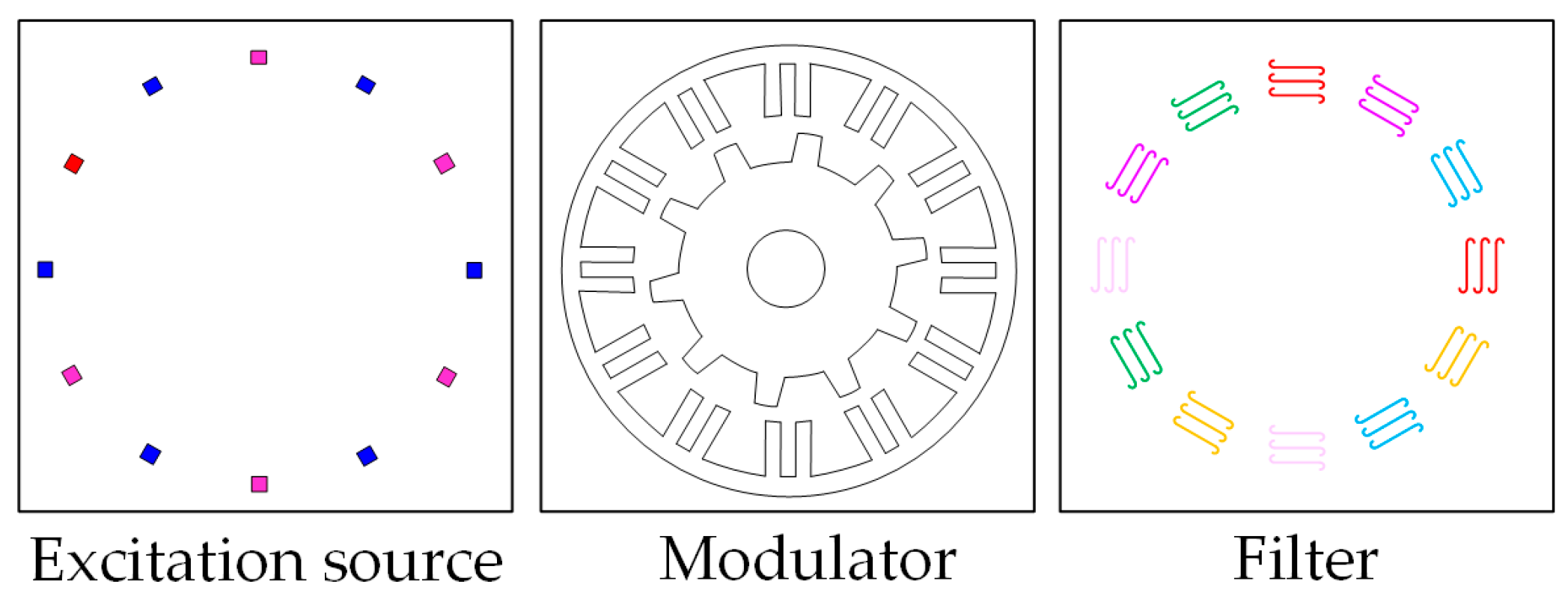
- Cheng, M.; Han, P.; Hua, W. General Airgap Field Modulation Theory for Electrical Machines. IEEE Trans. Ind. Electron. 2017, 64, 6063–6074. [Google Scholar] [CrossRef]
- Chen, Y.; Zhou, Y. Radial Displacement Sensorless Control of Bearingless Flux-Switching Permanent Magnet Machines Based on Difference of Symmetric-Winding Flux Linkages. IEEE Trans. Ind. Electron. 2021, 68, 7793–7803. [Google Scholar] [CrossRef]
- Pathak, K.; Franch, J.; Agrawal, S. Velocity and position control of a wheeled inverted pendulum by partial feedback linearization. IEEE Trans. Robot. 2005, 21, 505–513. [Google Scholar] [CrossRef]


| Parameter | Symbol | Value |
|---|---|---|
| Rotor gravity | G | 98 N |
| Shaft length | lr | 135 mm |
| Moment of inertia of the rotor radial | Ir | 0.16123 kg·m2 |
| Moment of inertia of the rotor tangential | IR | 0.00986 kg·m2 |
| Suspension-plane inductance | Lss | 0.004553 H |
| Self-inductance variation coefficient | Le | 1.4556 H/m |
| Amplitude of PM flux | ψfm | 0.0294 Wb |
| PM flux variation coefficient | ψem | 11 Wb/m |
| Performance | PID Method | Proposed Method |
|---|---|---|
| Stable suspension time in simulation | 200 ms | 100 ms |
| Steady-state rotor displacement | ±0.15 mm | ±0.07 mm |
| Maximum rotor displacement in step speed | ±0.2 mm | ±0.1 mm |
| Parameter dependence | Low | High |
| Complexity | Low | High |
| Loss | Low | High |
| Control accuracy | Low | High |
| Dynamic response | Slow | Fast |
Disclaimer/Publisher’s Note: The statements, opinions and data contained in all publications are solely those of the individual author(s) and contributor(s) and not of MDPI and/or the editor(s). MDPI and/or the editor(s) disclaim responsibility for any injury to people or property resulting from any ideas, methods, instructions or products referred to in the content. |
© 2023 by the authors. Licensee MDPI, Basel, Switzerland. This article is an open access article distributed under the terms and conditions of the Creative Commons Attribution (CC BY) license (https://creativecommons.org/licenses/by/4.0/).
Share and Cite
Chen, Y.; Yu, W.; Yang, R.; Cui, B. Suspension Flux Internal Model Control of Single-Winding Bearingless Flux-Switching Permanent Magnet Motor. Actuators 2023, 12, 404. https://doi.org/10.3390/act12110404
Chen Y, Yu W, Yang R, Cui B. Suspension Flux Internal Model Control of Single-Winding Bearingless Flux-Switching Permanent Magnet Motor. Actuators. 2023; 12(11):404. https://doi.org/10.3390/act12110404
Chicago/Turabian StyleChen, Yao, Wanneng Yu, Rongfeng Yang, and Bowen Cui. 2023. "Suspension Flux Internal Model Control of Single-Winding Bearingless Flux-Switching Permanent Magnet Motor" Actuators 12, no. 11: 404. https://doi.org/10.3390/act12110404
APA StyleChen, Y., Yu, W., Yang, R., & Cui, B. (2023). Suspension Flux Internal Model Control of Single-Winding Bearingless Flux-Switching Permanent Magnet Motor. Actuators, 12(11), 404. https://doi.org/10.3390/act12110404