Article

Octopus-Inspired Robotic Arm Powered by Shape Memory Alloys (SMA)

SoRobotics Lab, Department of Mechanical Engineering, College of Engineering, Wayne State University (WSU), Detroit, MI 48208, USA
*
Author to whom correspondence should be addressed.
Actuators 2023, 12(10), 377; https://doi.org/10.3390/act12100377
Submission received: 16 August 2023 / Revised: 24 September 2023 / Accepted: 29 September 2023 / Published: 4 October 2023
(This article belongs to the Special Issue Soft Actuators and Robotics)

Abstract

:
Traditional rigid grippers that are used for underwater systems lack flexibility and have lower degrees of freedom. These systems might damage the underwater environment while conducting data acquisition and data sampling. Soft robotics, which is mainly focused on creating robots with extremely soft materials are more delicate for the grasping of objects underwater. These systems tend to damage the underwater ecosystem in the least possible way. In this paper, we have presented a simplified design of a soft arm inspired by the octopus arm actuated by coiled Shape Memory Alloys (SMAs) using completely flexible lightweight material. The characterization arm performance under various load and input current conditions is shown. We hope this work will serve as a basis for the future of underwater grasping utilizing soft robotics.

1. Introduction

Traditional robotic systems that are used for various applications such as medical, manufacturing, as well as exploration are always a bit invasive to the environment they are working in. This is due to the rigid body components of such systems. Even though rigid robotic systems get the job done, they can be inefficient, large, bulky, and expensive, making them unfavorable for delicate tasks. Work is being carried out to increase the efficiency of such systems. However, a better approach would be to take inspiration from a highly advanced system that has been evolving for billions of years: Nature.
Engineering problems can be approached by taking inspiration from nature’s solution to various problems. This design, known as the biomimetic design approach, uses natural principles, structures, and processes as a basis for innovation and problem-solving in a wide range of fields. Soft robotics is another field that makes use of soft and flexible materials, such as silicone and elastomers, and allows the robotic system to adapt to its environment, conform to different shapes, and exhibit behaviors like living organisms. One of the key benefits of using biomimetic soft robots is that they can help to create more sustainable and efficient products and systems. A biomimetic system can use various actuation techniques depending on its application. Many such robotic systems make use of artificial muscles as their actuation technique and sensors. Artificial muscles are used to mimic the function of biological muscles when subjected to an external stimulus. Some examples of artificial muscles that can be used in biomimetic soft robots are Electroactive Polymers (EAPs) [1,2] that change their shape in response to an electric current, Pneumatic Artificial Muscles (PAMs) [3,4] that are made from elastomeric tubes which expand when they are pressurized, Twisted and Coiled Polymer muscles (TCPs) [5,6,7] and Shape Memory Alloys (SMAs) [8,9] that contract and expand in response to change in temperature. Each of the actuation techniques, including all the artificial muscles, has its advantages and disadvantages. A trade-off of one property while compensating for another property is necessary while developing any robotic system. Selecting an actuator that is compatible with the structure and can accomplish the designed tasks efficiently is critical to the success of the robotic system.
For underwater applications, although electroactive polymers and pneumatic artificial muscles work, their performance is greatly affected by the conductivity of the surrounding water medium. The performance and the actuation capacity of Shape Memory Alloys (SMAs) and Twisted and Coiled Polymers (TCPs) remain unaffected even if they are used in the underwater medium. While electrical motors and fluidic actuators are energy efficient and easily controlled, they tend to be bulky, expensive, and produce a lot of noise and disturbances in an underwater environment. Hence, using SMAs and TCP muscles is a great alternative to using traditional actuation techniques. On top of these advantages, artificial muscles such as TCPs and SMAs also have higher force density [10], higher strain [7,11,12], faster actuation [13], high endurance [5,14], and are lightweight.
The promising results of the Twisted and Coiled Polymer (TCPs) muscle behavior were shown by Haines et al. [15] and opened new ways in which these muscles can be created and modified. The behavior of these muscles embedded inside a soft silicone material was further investigated, and the optimized parameters were observed in [7]. Moreover, these muscles have demonstrated good grasping abilities in the remotely controlled octopus robot [6]. There has been research to investigate the inculcation of TCPs in devices for medical use. One such attempt is presented in [16], where a hand orthosis device has been fabricated and investigated. TCPs have also been used to accurately mimic the locomotive swimming nature and the appearances of a couple of jellyfish found in nature, namely, Chrysaora achlyos [12,14,17]. Another artificial muscle whose performance is unaffected due to the conductivity of the surrounding medium, specifically, in underwater environments is the Shape Memory Alloys that remember their memory shape and revert to it when the temperature increases.
Previously, SMAs have been employed in soft robots to mimic various aspects of the animals found in nature. The potential of linear Shape Memory Alloys coupled with silicone rubber tubes in a soft robotic actuator for gripping objects has been demonstrated [18]. A robotic structure that can swim in multiple directions using linear SMAs confined in a conduit and actuated by electrical current stimulation and mimics the appearance and biological locomotion of a jellyfish found in nature, Chrysaora Colorata is presented in [5]. Coiled SMAs have been used to create a soft robotic hand able to lift off weight up to 130 g through the process of Joule heating [19]. Coiled SMAs can be easily fabricated from linear SMAs. One such study presents the fabrication of coiled SMAs from linear SMAs and the characterization of the resulting coiled SMAs for using them in humanoid robots [10]. Hence, both coiled and linear SMAs have very high potential in applications for soft robots. Some advantages of using these artificial muscles in underwater soft robots are that they are flexible, noninvasive to marine life, durable, and typically have a low cost of operation. However, researchers are working on solving the challenges faced in developing these robots. Some of the challenges faced are the development of small, efficient, lightweight power sources and control systems, durability, and control due to the lack of rigidity in them, scaling up a soft robot also becomes a challenge as when the soft materials become larger, they tend to become less and less stable. Mimicking the anatomy and physicality of an octopus arm is a common solution for underwater manipulation due to its high degree of freedom. Varying octopus-inspired designs and actuation methods have been presented such as tendon-driven [20,21,22], actuated by SMAs and EAPs [2,23,24,25,26], hybrid actuation using stepper motors and fishing line TCP [6], pneumatics and fluidic [3,4,27,28,29,30]. Some insights regarding creating soft robots while having a minimum invasion of marine life are presented in the survey paper [31]. One of the first attempts at creating a biomimetic robot that moved on its own without requiring an external power supply was the Octobot [27], which is a 3D-printed soft-bodied autonomous robot. PoseiDRONE is a robot mimicking the maneuverability of an octopus through jet propulsion by the virtue of its equidistant arms around the body [21]. A dynamic model of a completely soft octopus-mimicking robot with an elastomeric main body has been presented in [32]. A bipedal walking of a soft robot inspired by a coconut octopus has been studied. The gait analysis of the bipedal octopus is presented along with the design of the mechanical structure and the control systems [33].
In this paper, a simplistic version of a biomimetic soft robotic octopus tentacle using coiled Shape Memory Alloys embedded in Ecoflex silicone is presented. The bending angle characteristics of the arm are studied when it is freely suspended with and without weights attached at the tip in an underwater environment and subjected to Joule heating (some examples are presented in supplementary movie S1). A simple temperature model is created that can be used to predict the temperature of an SMA when it is actuated under embedded conditions. The key highlights of this work can be summarized as follows:
  • We introduce a modular and lightweight bio-inspired robotics arm. The design is simple and emphasizes flexibility utilizing artificial muscles as actuators.
  • We develop a predictive temperature model for the coiled SMAs when actuated in silicone. This model aids in studying the control behavior of the SMAs during operation.
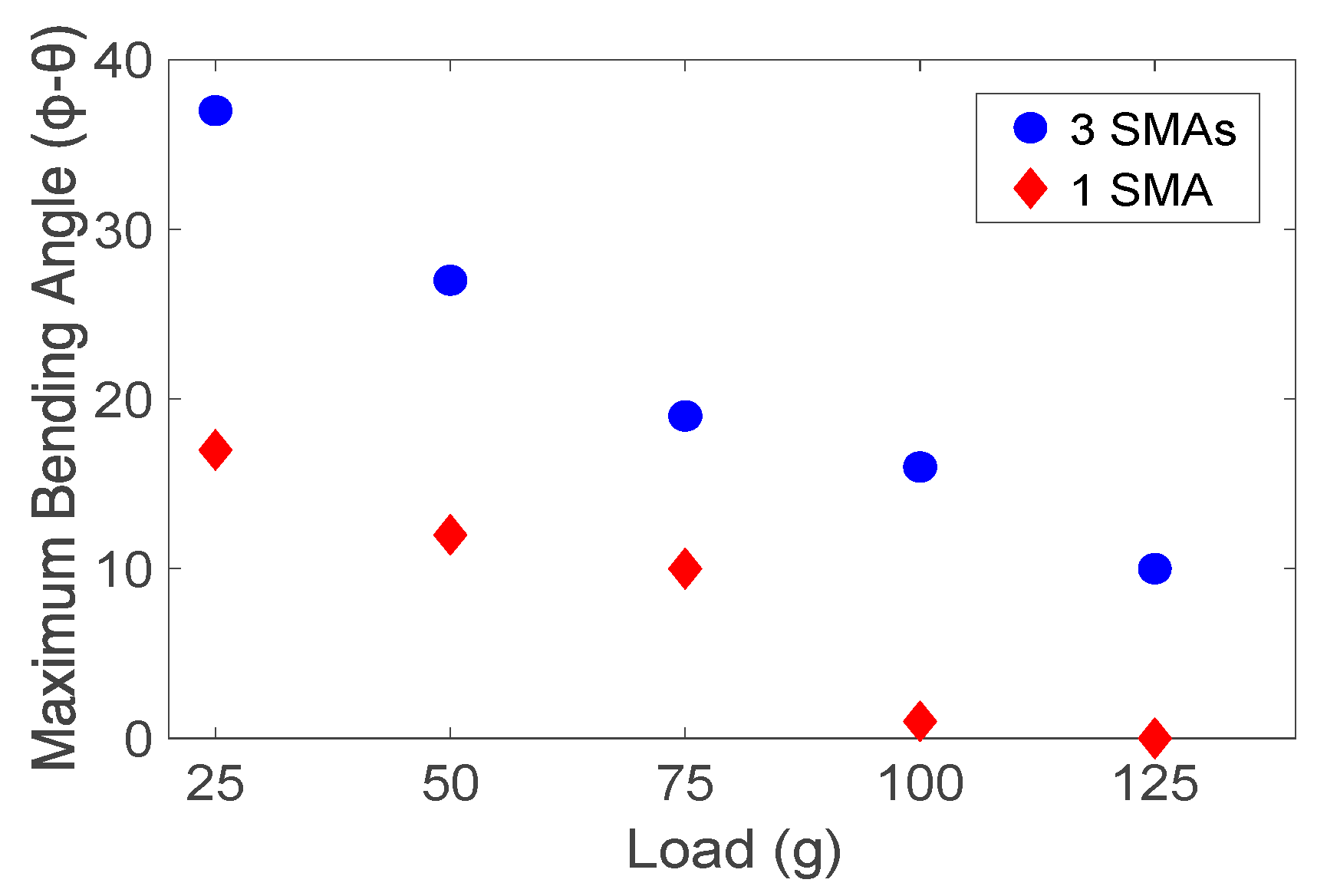
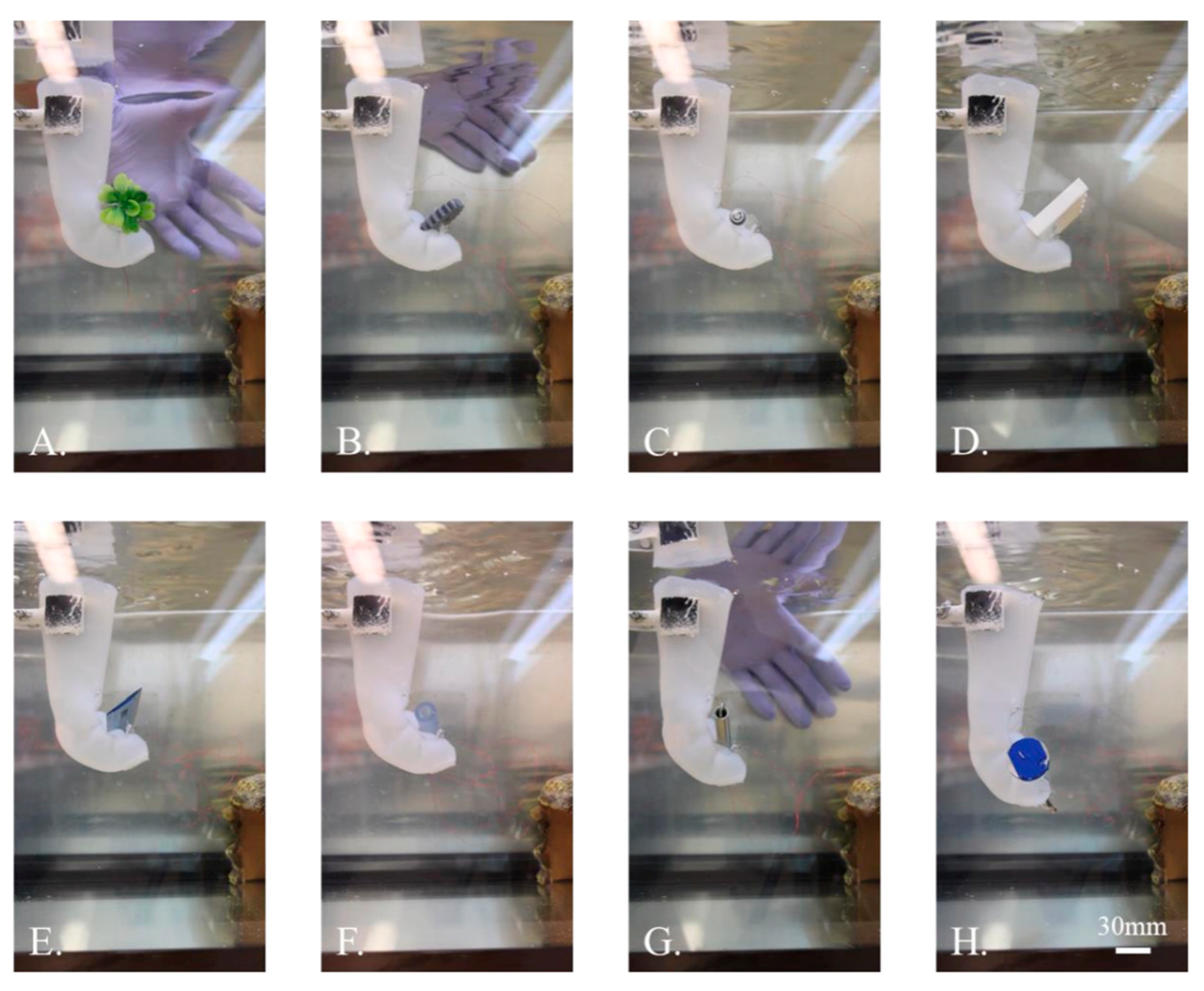
  • Extensive actuation analyses reveal the arm’s capabilities, including controllable 2D and 3D bending, a lifting capacity of up to 125 g, and the ability to grasp and hold objects of diverse sizes and shapes.

2. Materials and Methods

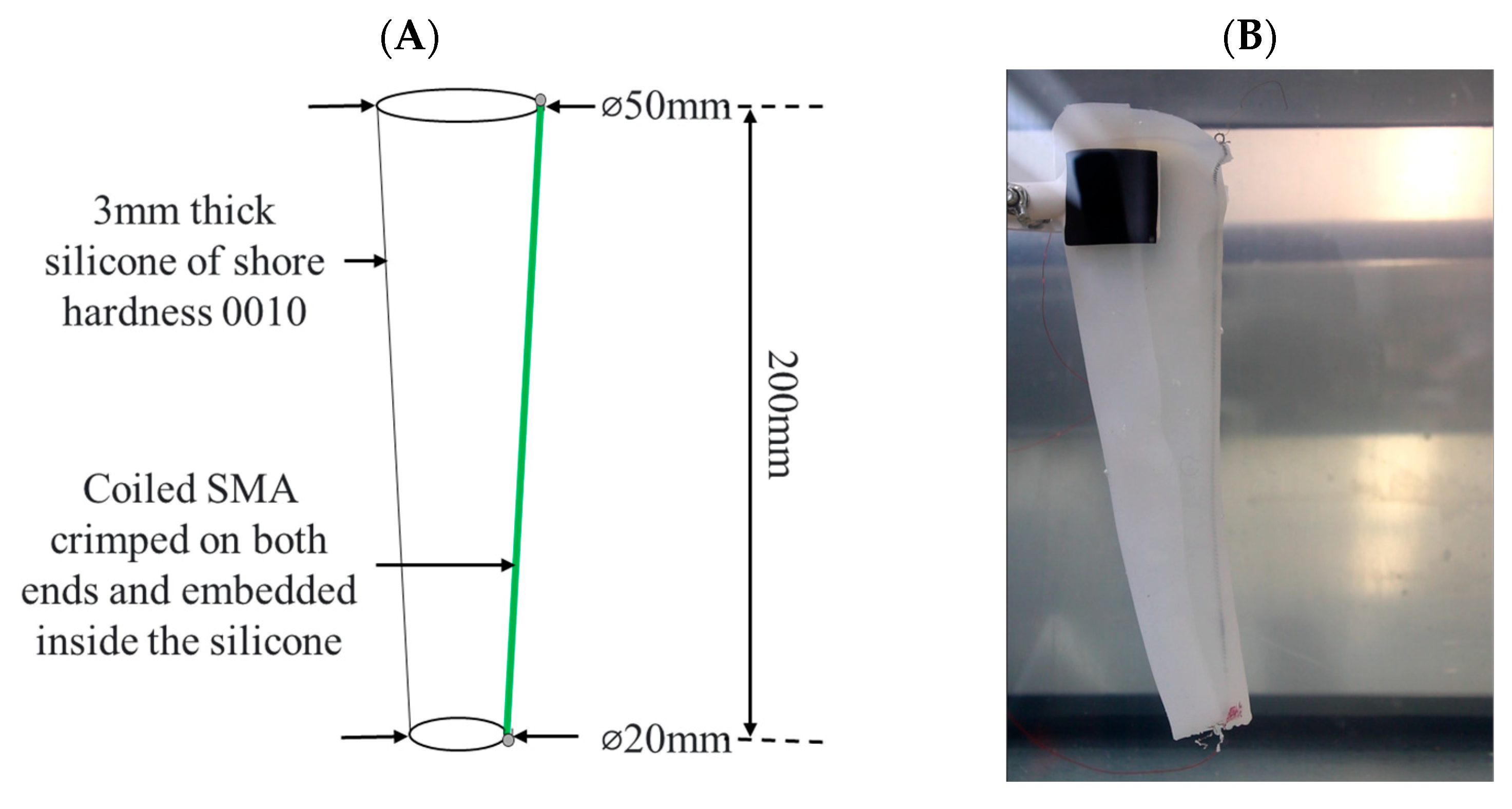
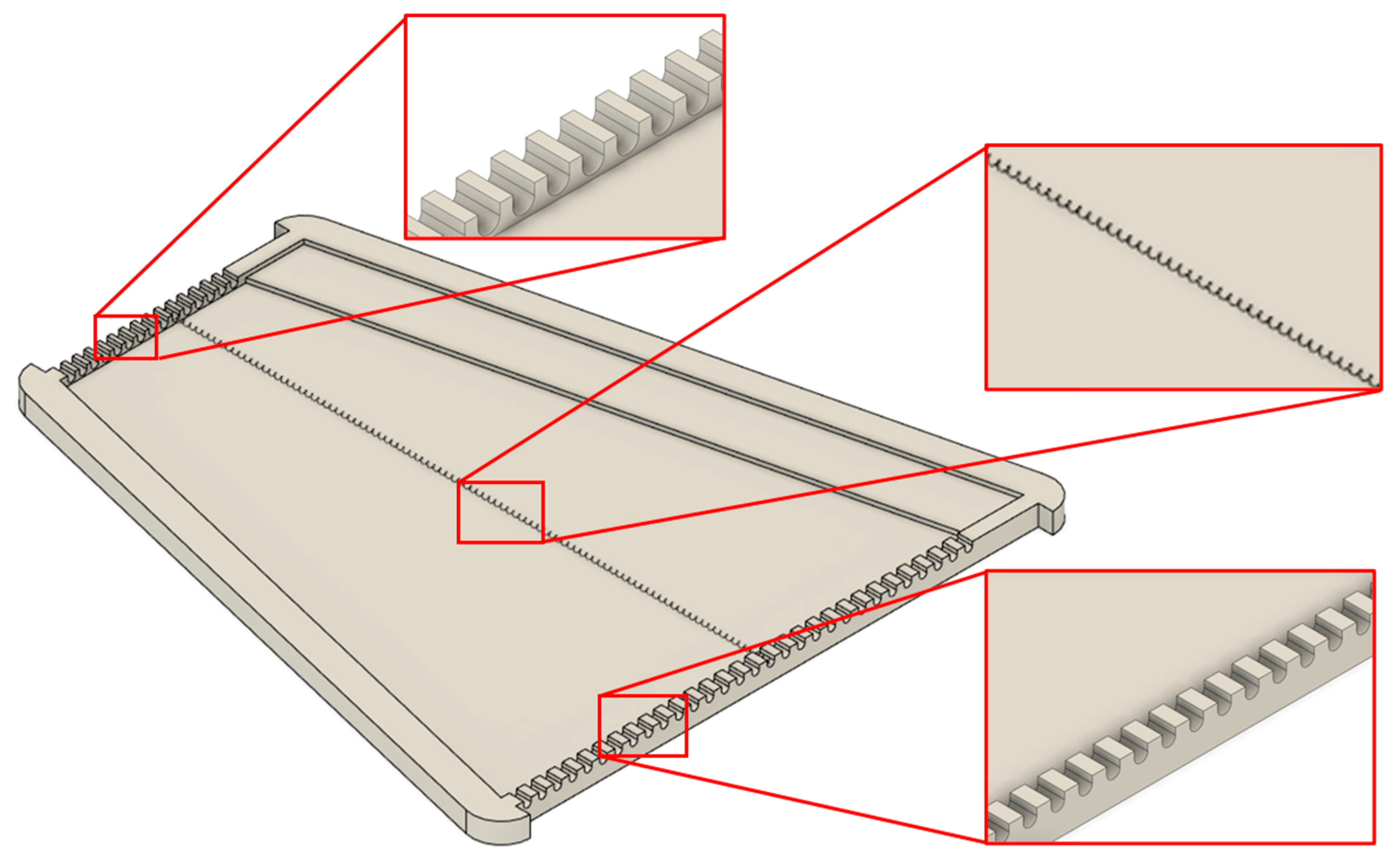
2.1. Design of the Silicone Arm with Embedded Coiled SMA

The proposed silicone arm shown in Figure 1 was created by embedding the coiled Shape Memory Alloys inside Ecoflex silicone with a shore hardness of 0010. The arm is in the shape of an inverted frustum of a cone with a base diameter of 50 mm and a truncated diameter of 20 mm with a silicone thickness of 3 mm. The total length of the arm is 200 mm. A coiled SMA with a spring wire diameter of 0.008” (0.203 mm) and spring outer diameter of 0.054” (1.37 mm) is crimped on both ends and embedded inside the silicone.

2.2. Fabrication Methods Used for Creating the Silicone Arm

The three-dimensional silicone arm is created by folding a trapezoidal silicone sheet into a truncated cone shape, as shown in Figure 1. To create the trapezoidal sheet, the CAD of the mold is designed in Fusion 360 and is 3D printed with PLA filament using Lulzbot Taz 5, as shown in Figure 2.
The mold has multiple slots to fix the crimped SMA in place before embedding it in silicone. The slots are 2.5 mm in diameter and are centered 2.5 mm from the top surface of the mold. The silicone curing area of the mold is 3 mm thick, and the sides are equal to the circumference of the diameters of the arm. The smaller base of the trapezium is 60 mm long, while the larger base is 160 mm long. A lip of 20 mm is added at the side of the trapezium to seal the 2D sheet into a 3D truncated cone.
Firstly, the length of the SMA coil is chosen in such a way that when the coil is tensioned with a pull force of 0.089 pounds (38.3 g), the length becomes 200 mm. The compressed spring is hung vertically, and a calibrated weight of 38.3 g is attached to it. After tensioning the coil, the 3D-printed PLA mold is sprayed with a BK30 mold-release lubricant. The tensioned and crimped SMA is fixed in the mold, as shown in Figure 2. Next, 40 mL each of parts A and B of the platinum-cured Ecoflex 0010 were mixed and poured over the SMA fixed on the PLA mold. The silicone is set for curing at room temperature for 4–5 h. After the silicone is cured, the flat sheet of silicone that is embedded with the SMA is carefully removed from the mold, and the excessive silicone around the edges is cut. The 2D flat sheet is then folded over the sides, and the lip is sealed over the arm with small amounts of fast-curing Ecoflex 0035.

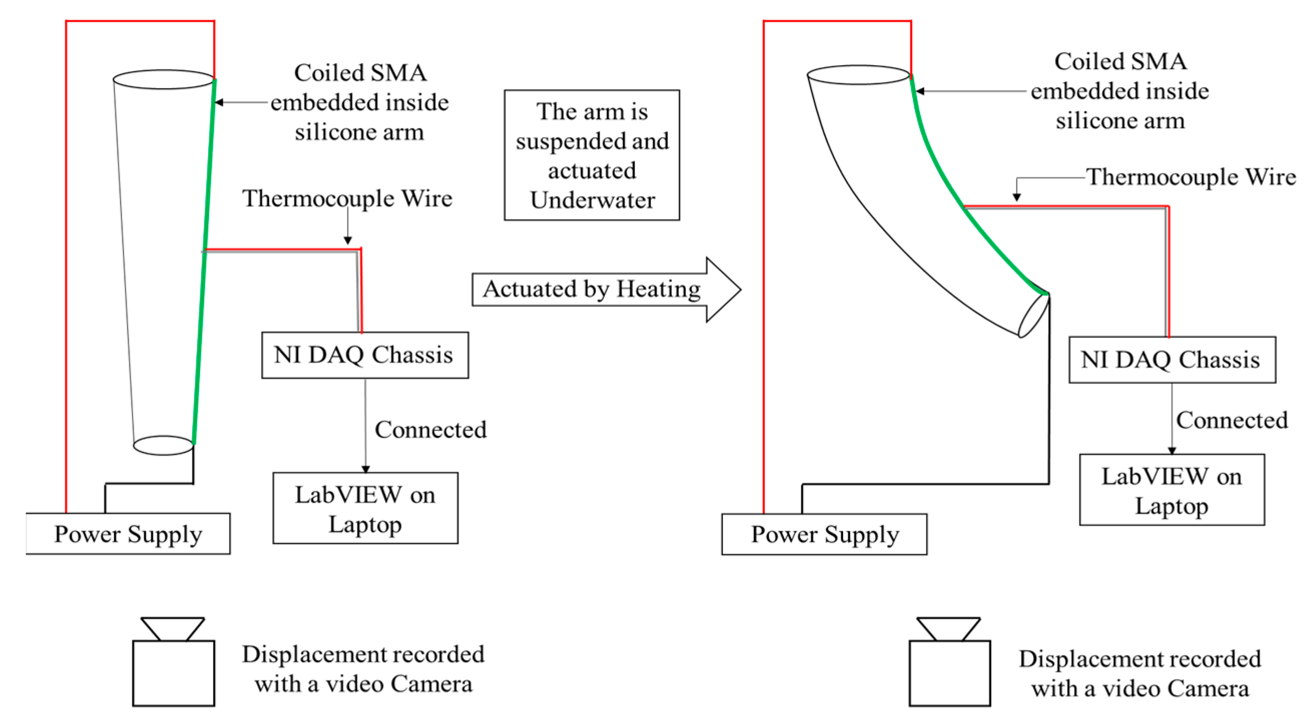
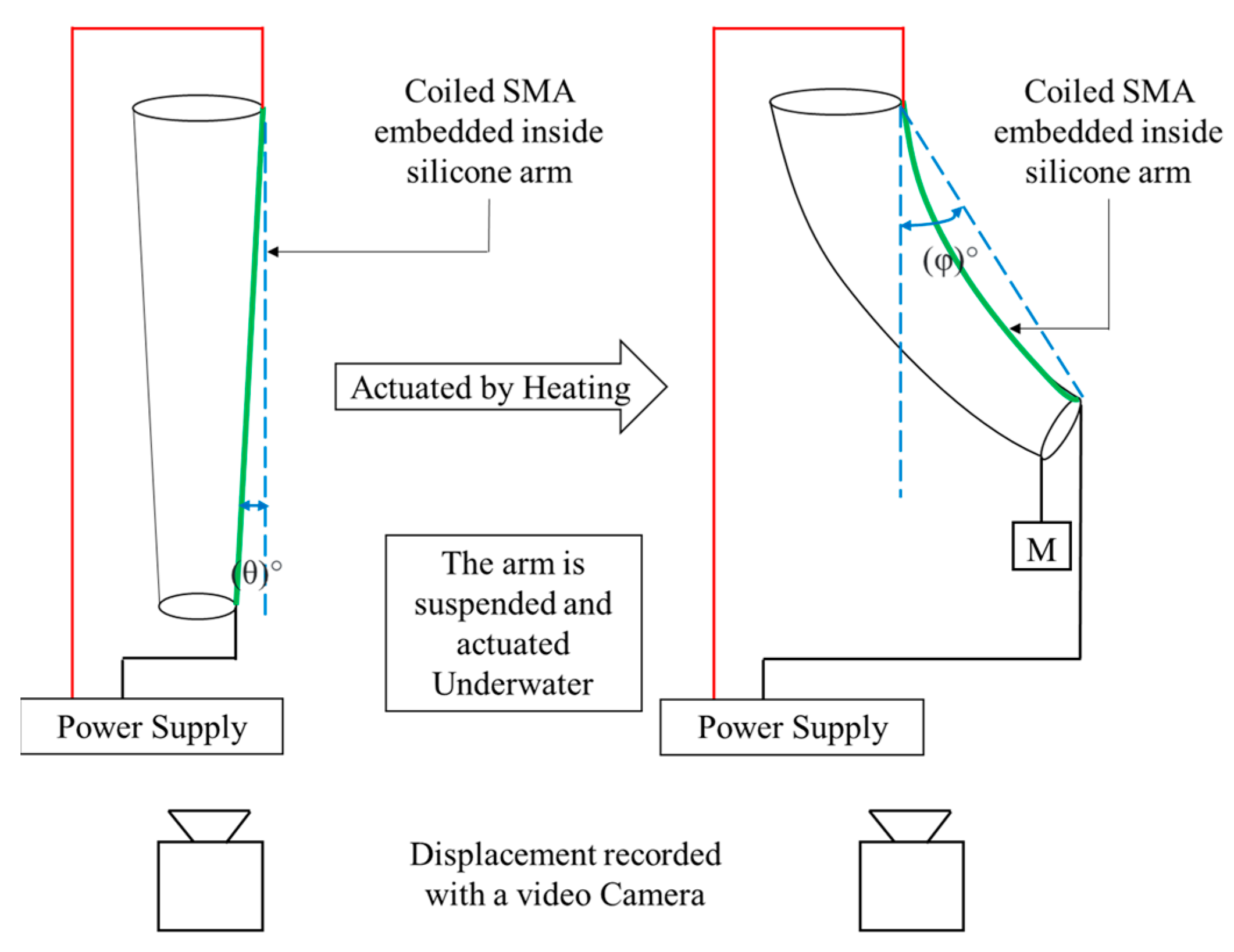
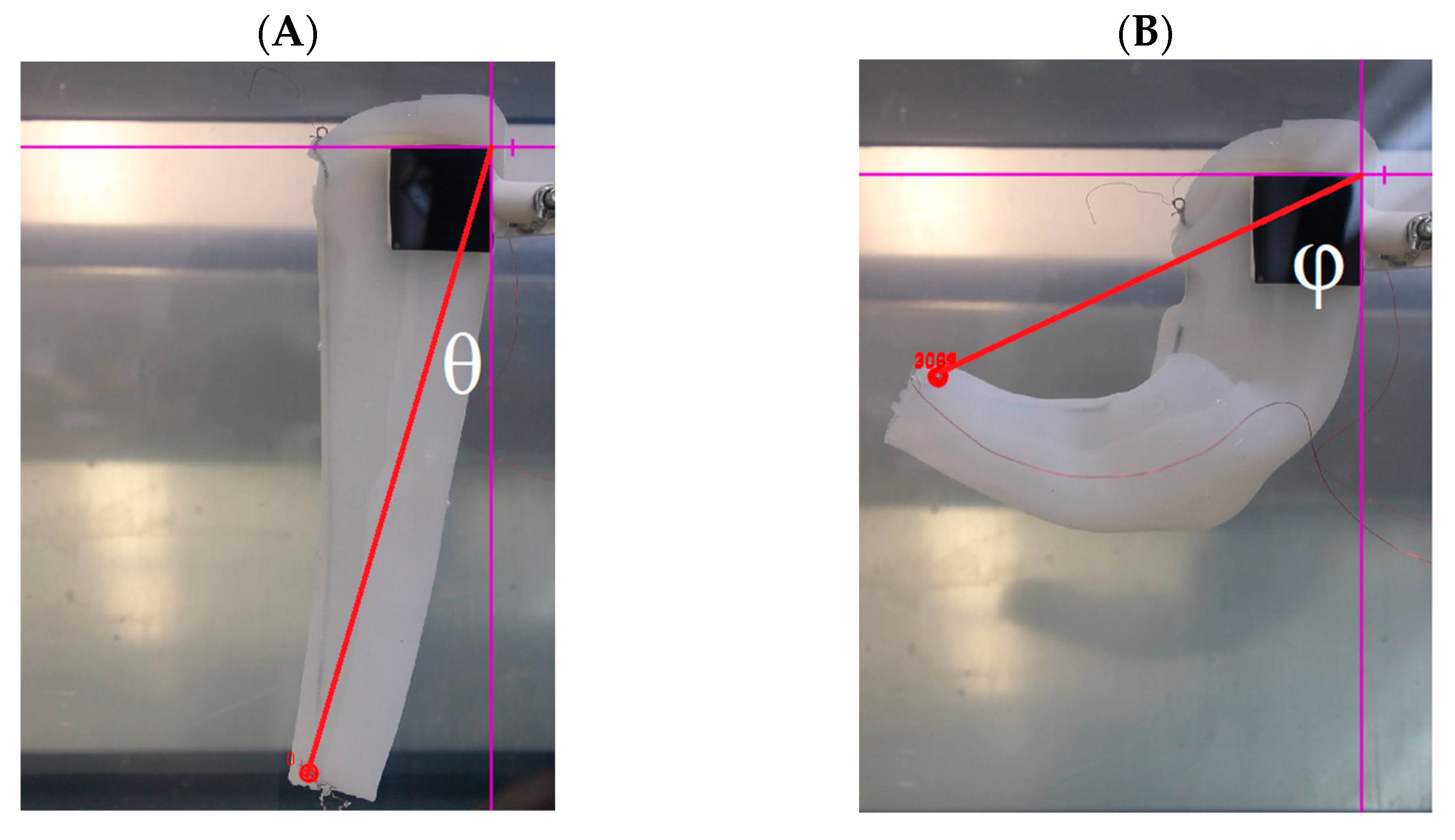
2.3. Experimental Setup of the Bending Characteristics of the Arm

The silicone arm is suspended in a tank underwater such that the SMA is exactly on the side of the arm, as shown in the schematic in Figure 3. The value of M for studying the bending characteristics is 0 g, as no weight is attached to the tip of the arm. The SMA embedded inside the arm is actuated with all combinations of 1.125 A–1.5 A with an interval of 0.125 A and heating times of 2 s–5 s with an interval of 1 s and the cooling time of 45 s underwater. All the actuation cycles were captured in a video recording.
The final videos of the actuation cycles were analyzed in Tracker Physics software. As shown in Figure 4A,B, a cartesian coordinate system was set up with the origin at the corner of the fixed stand. The final bending angle (plotted below) is given by the expression (φ − θ), where φ and θ are as shown in the figure below. The bending angle of the arm with respect to the initial position as described in the mathematical description was studied as a function of the actuation current and actuation time.

2.4. Weightlifting Characterization of the Single SMA Embedded Inside the Silicone Arm

The experimental setup for performing the weightlifting capabilities of the SMA coil is shown in Figure 3, except that the mass M is nonzero in the case of the weightlifting characterization.
The broader end of the arm was hung with the help of a stand, as shown in Figure 5A. The other end of the arm was free to move. Figure 5B,C show the full displacement of the tip of the silicone arm when no weight is attached to the other end and with weight, respectively. The arm was actuated with the same combinations of the current and the heating times. Standard calibrated weights of 25 g, 50 g, and 75 g were used for this experiment. The bending angle of the arm with respect to the initial position when weights are attached with the help of a fishing line was recorded.

2.5. Temperature Modeling of the SMA Embedded in the Silicone Arm

The coiled SMA embedded silicone arm is suspended underwater with the help of a lab stand. The J-type thermocouple wire which is connected to a NI-cDAQ 6178 chassis is inserted in the silicone and wound on the SMA coil in the geometrical center to obtain the temperature readings that are not affected by the extremities. The NI-cDAQ 6178 chassis reads the temperature of the coil with the help of LabVIEW. The frequency of the data acquisition is 10 Hz (explained in Figure 6). A simplistic analytical temperature model of the arm is developed to predict the temperature of the SMA coil. One can say from the first law of thermodynamics using Equation (1),
m C p d T d t = h A T T + I 2 R
Integrating this equation, we obtain Equation (2),
T = T + I V h A 1 e x p h A t m C p
The values and the descriptions of each of the parameters in Equations (1) and (2) are given in Table 1.
Equation (1) is a first-order differential equation containing the rate of change of temperature with respect to time and the temperature of the SMA coil at that specific time. To solve this equation, a Simulink model is created in MATLAB. The input to the Simulink model is the parameters as defined in Table 1. The experimental temperature output of LabVIEW in each case is recorded and plotted against time. In this section, the model was validated with the help of the experimental temperatures. The model was run alongside combinations of temperatures in which either only the current is varied or only the heating time is varied.

3. Results and Discussion

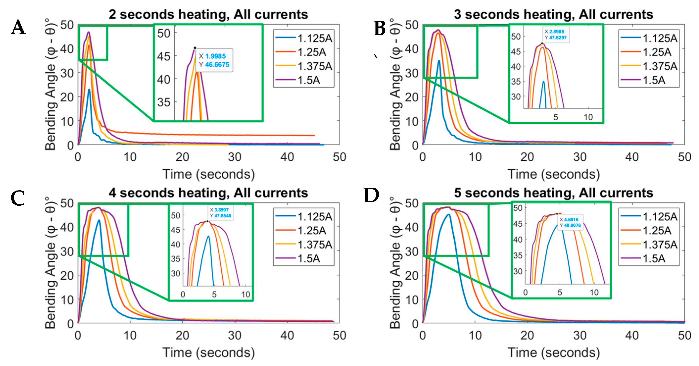
3.1. Bending Characterization of the Silicone Arm

Figure 7A–D show the bending angle of the tip of the arm vs. time for the currents used. As expected, a higher bending angle is caused by actuating the SMA with a higher current and a corresponding higher heating time. However, as can be seen in Figure 7B, the bending angle peaks at a minimum current of 1.25 A and a corresponding minimum time of 3 s. The maximum bending angle achieved is about 48°, as can be seen in Figure 7. This peak angle can be set as the limit of the silicone arm above which the arm is not able to bend.
For some heating time and current combinations (for example, 1.125 A for 2 s of heating), the tip of the arm does not reach the maximum bending angle. For most such cases, it can be said that the coil is not getting enough time to be heated, and the surrounding silicone and water are cooling the coil before it can reach the actuation temperature. For most higher current and heating time combinations, the displacement reaches the maximum value of displacement before the heating time ends. In such cases, as the tip has already reached maximum displacement, further supplying current to the coil heats the coil excessively. This excessive heat may damage the SMA coil or the silicone arm. If the SMA coil is repeatedly supplied with excessive heat while it is under tension, it may cause the coil to change its memory shape effect due to the martensite–austenite phase transformation. Such an alloy with a changed memory shape does not “remember” the original shape. Thus, as a result, the coil is no longer useful.

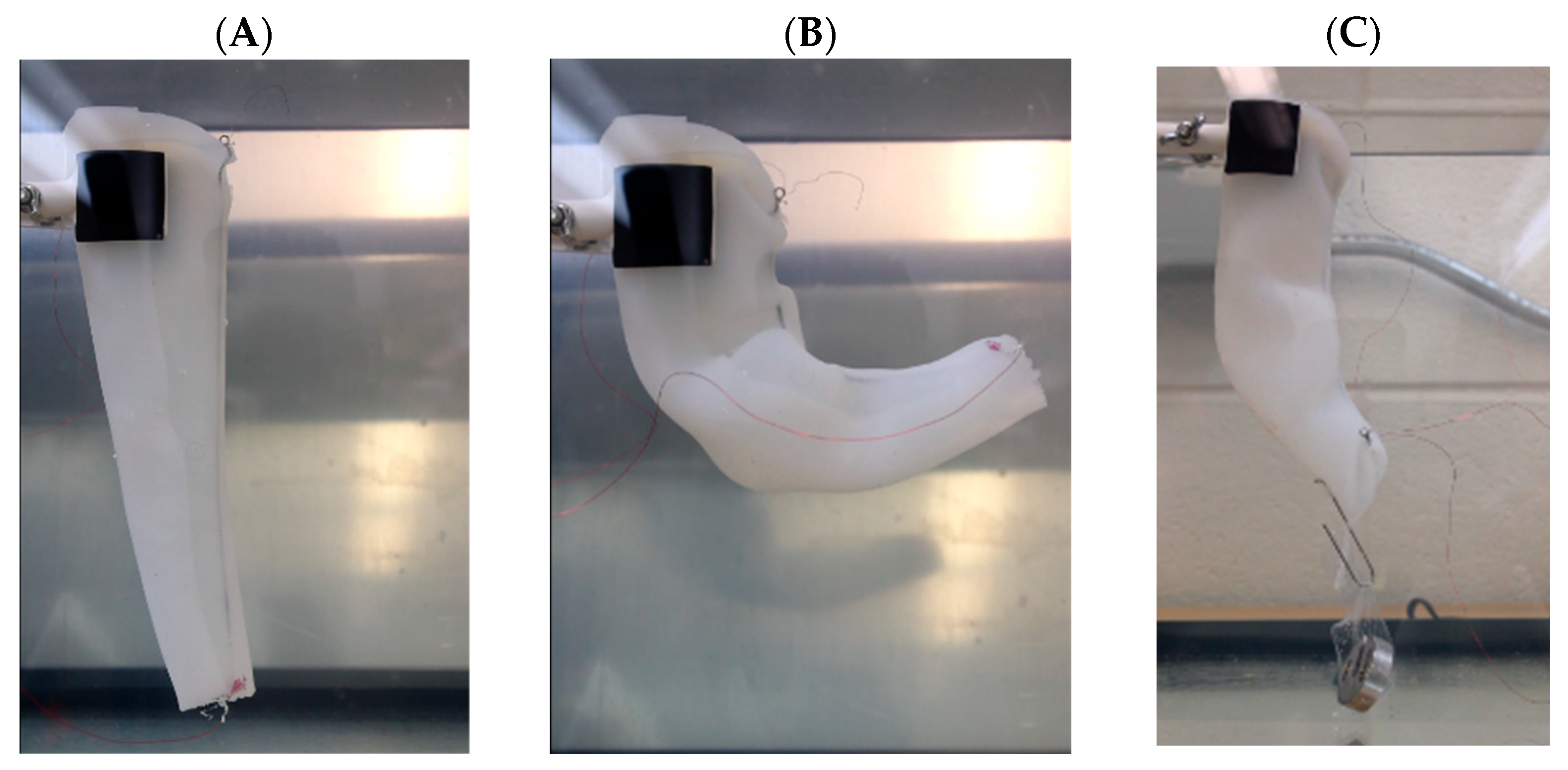
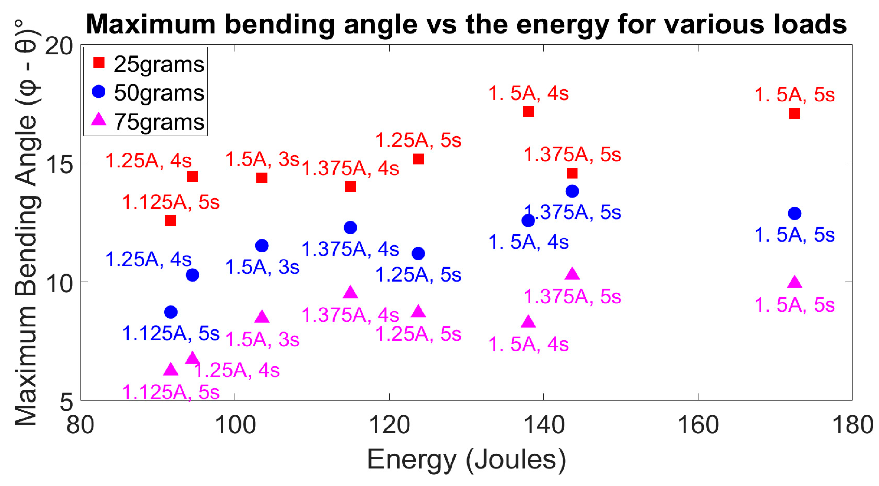
3.2. Weightlifting Characterization of the Arm with a Single Embedded Coiled SMA

In the weightlifting characterization experiment, the bending angle and the actuation voltage were recorded for all current and time combinations. The overall energy transferred to the SMA (Q = VIt) is calculated and tabulated below. The bending angle was plotted against the calculated energy for different loads that the arm was able to lift off the bottom of the fish tank.
From Figure 8, on average, the bending angle for the lower mass of 25 g is higher than the corresponding bending angle for the higher mass. The heat consumed, which is plotted on the X-axis, is a function of the voltage, the current, and the time. When the SMA coil is heated up to actuate it, the temperature of the coil increases due to Joule heating. This, in turn, reduces the resistance of the coil. As a result, the voltage across the coil is not constant but is constantly changing. For this experiment, the resistance is assumed to be constant throughout the experiment. Hence, although some points show deviation from one another in terms of the bending angle with respect to the energy consumed, the differences can be assumed to be in the experimental uncertainty.
It can be seen from the figure above that for low actuation current and low time, the bending angle of the tip of the arm does not reach its maximum potential. For a relatively lower load of 25 g on the arm, the maximum bending angle reaches 12.5°, whereas for a higher load of 75 g, the single-coil SMA arm can reach a maximum bending angle of 6° only. For all the loads and the current and time combinations, the bending angle peaks at around 130 J–140 J of electrical energy. At around 140 J, a maximum bending angle is achieved. This peak angle is around 17° for 25 g, 13° for 50 g, and about 10° for 75 g, as can be seen in Table 2. If a higher energy is supplied, by either increasing the current and/or the heating time of actuation, the bending angle saturates. However, the desired curling shape is achieved much faster than the curling shape with lower current and time combinations. The energy used is a trade-off between the frequency of actuation and the energy consumed during the experiment. If little to no energy is to be wasted in increasing the temperature of the coil excessively, then one has to trade off the faster frequency. However, if the arm is to be used in an application that requires higher frequency, then high energy can be supplied, and as a result, the measurable qualities such as efficiency and the overall life of the SMA are compensated.
Through the previous experiments, it was found that the input energy of 140 J allows the arm to reach the maximum bending angle during weightlifting. All energy supplied higher than 140 J goes into increasing the temperature of the coil without changing the shape of the silicone arm. Prolonged exposure to such high energy can cause the SMA coil to be damaged and change its original memory shape. Hence, the optimal energy to be supplied to the single-coil SMA embedded in a similar silicone arm is around 140 J, which can be achieved by passing 1.5 A for 4 s or 1.375 A for 5 s.

3.3. Weightlifting Characterization of the Arm with Multiple Embedded Coiled SMAs

Similar to the previous section, SMAs are embedded in the silicone; in this case 3 SMAs are embedded in parallel close to each other. The bending angle is recorded while carrying various loads. The arm shows good weightlifting capabilities when 3 SMAs are actuated together. This shows a linear trend between the number of SMAs embedded and the maximum weight it can carry. In this case we found that 3 SMAs, of the same coiled diameter, can carry up to a 125 g load with acceptable bending (~10o). The current and time combination used for the 3 SMAs is the same as for the single SMAs (multiplied by number of SMAs). Figure 9 shows the bending angle vs. load of 3 SMAs embedded vs. 1 SMA embedded. The results show a significant increase in the bending angle. We assume that increasing the number of SMAs embedded will further enhance the capability.

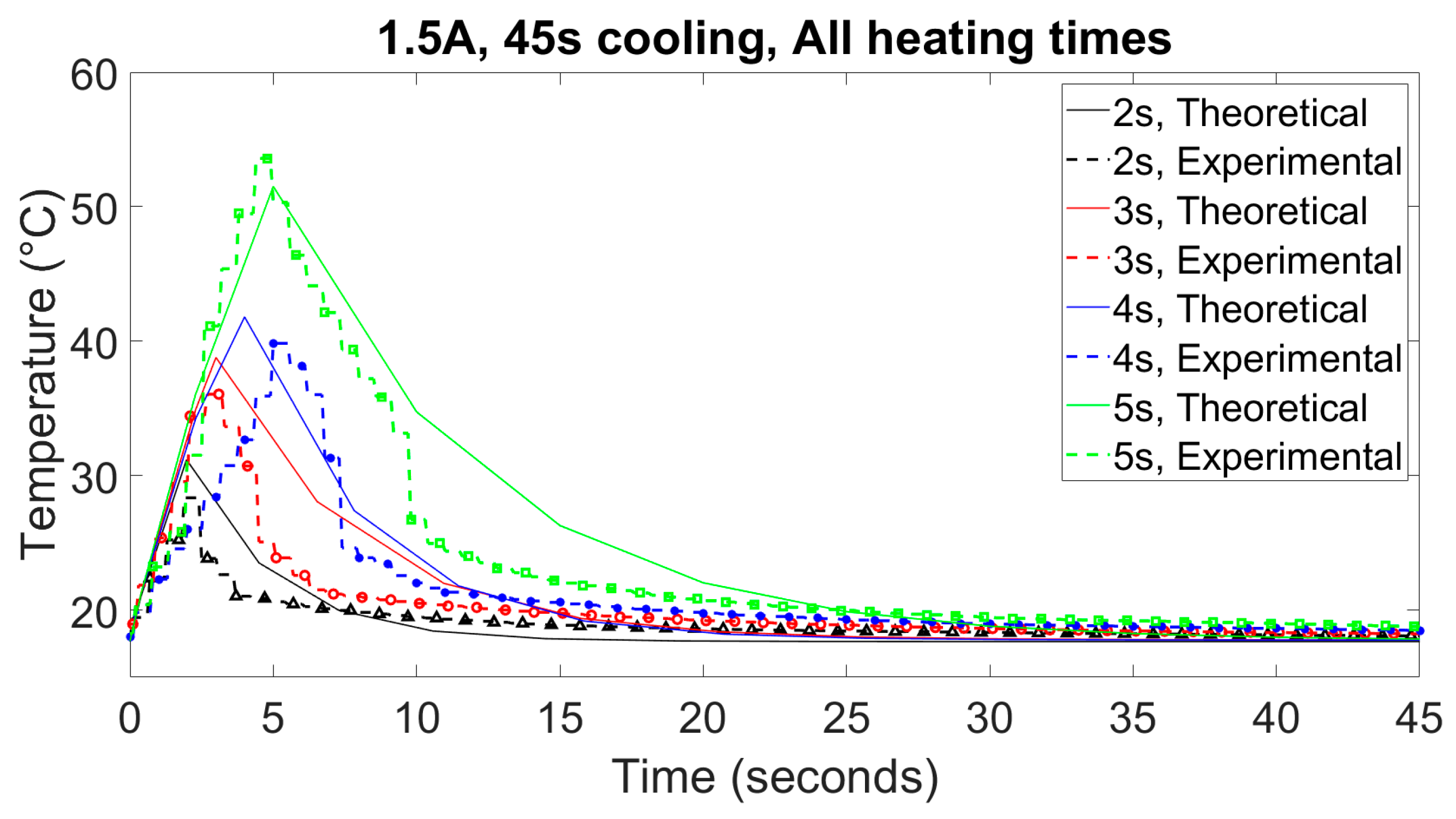
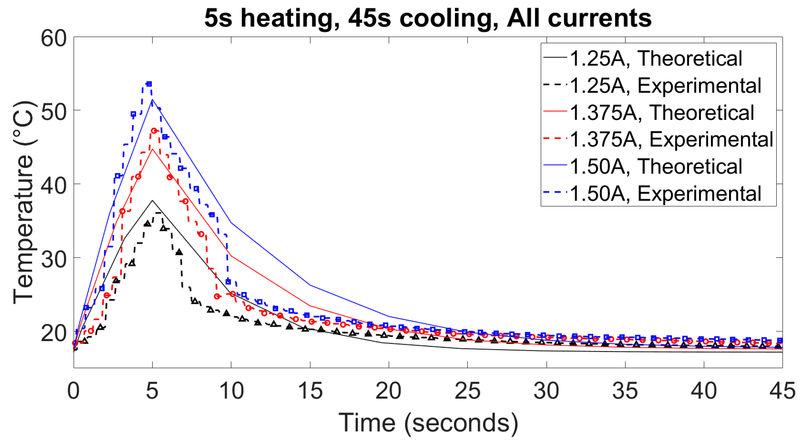
3.4. Temperature Modeling of the Single SMA Coil Embedded in a Silicone Arm

The bending angle of the tip of the silicone arm is directly proportional to the temperature of the SMA coil. A low temperature of the actuated SMA results in a lower bending angle of about 20° for a combination of low current (1.125 A) for a low time (2 s). This is because the electrical energy supplied to the coil is not enough to raise the temperature of the coil to activate the shape memory effect. For most combinations of current and time, the temperature of the coil almost reaches the required value for the actuation to begin and activate the shape memory effect. Similar observations as section B can be made about these results as well, that if excessive energy is passed through the coil, then the resulting bending angle will not be more but will be limited at a certain value. All the energy transferred to the circuit after the limiting value will increase the temperature of the SMA coil and might destroy it.
Two types of temperature modeling results are shown in Figure 10 and Figure 11, respectively. In Figure 10, the created model demonstrates the comparison between the experimental temperature and the analytical temperature obtained from the model presented in Equation (2) for an actuation current of 1.5 A for 2, 3, 4, and 5 s. In this test, the heating time is changed, which results in the change of the duty cycle, which is one of the crucial variables in the whole model. The other type of model demonstrates the comparison between the experimental temperature and the analytical temperature obtained from the model for a heating time of 5 s and a cooling time of 45 s for 1.25 A, 1.375 A, and 1.5 A of actuation current. In this type of model, the current is changed, which results in the change of voltage and the expression for h only.
Together, the results from these 2 models can be superimposed on one another, which results in a model that can predict the temperature of the SMA coil embedded inside the silicone arm when the current is changed and/or the heating time of the actuation cycle is changed. Thus, these 2 models were created individually and will be superimposed as and when needed. By performing this, a bigger model that predicts the temperature when both the current and the duty cycle changes can be created. Figure 10 shows the comparison between the experimental and analytical temperatures for 1.25 A, 1.375 A, and 1.5 A for a heating time of 5 s and a cooling time of 45 s.
As the model is designed for the heating cycle of the actuation only, for all the heating times, the model predicts a temperature that is closer to the experimental temperature. However, for the cooling cycle of the actuation, the model shows a difference between the experimental temperature and the model temperature. We can use these results to form a relation between the actuation parameters of the SMA and the arm bending, hence reducing experimental time and cost to develop a more robust soft arm for underwater application.

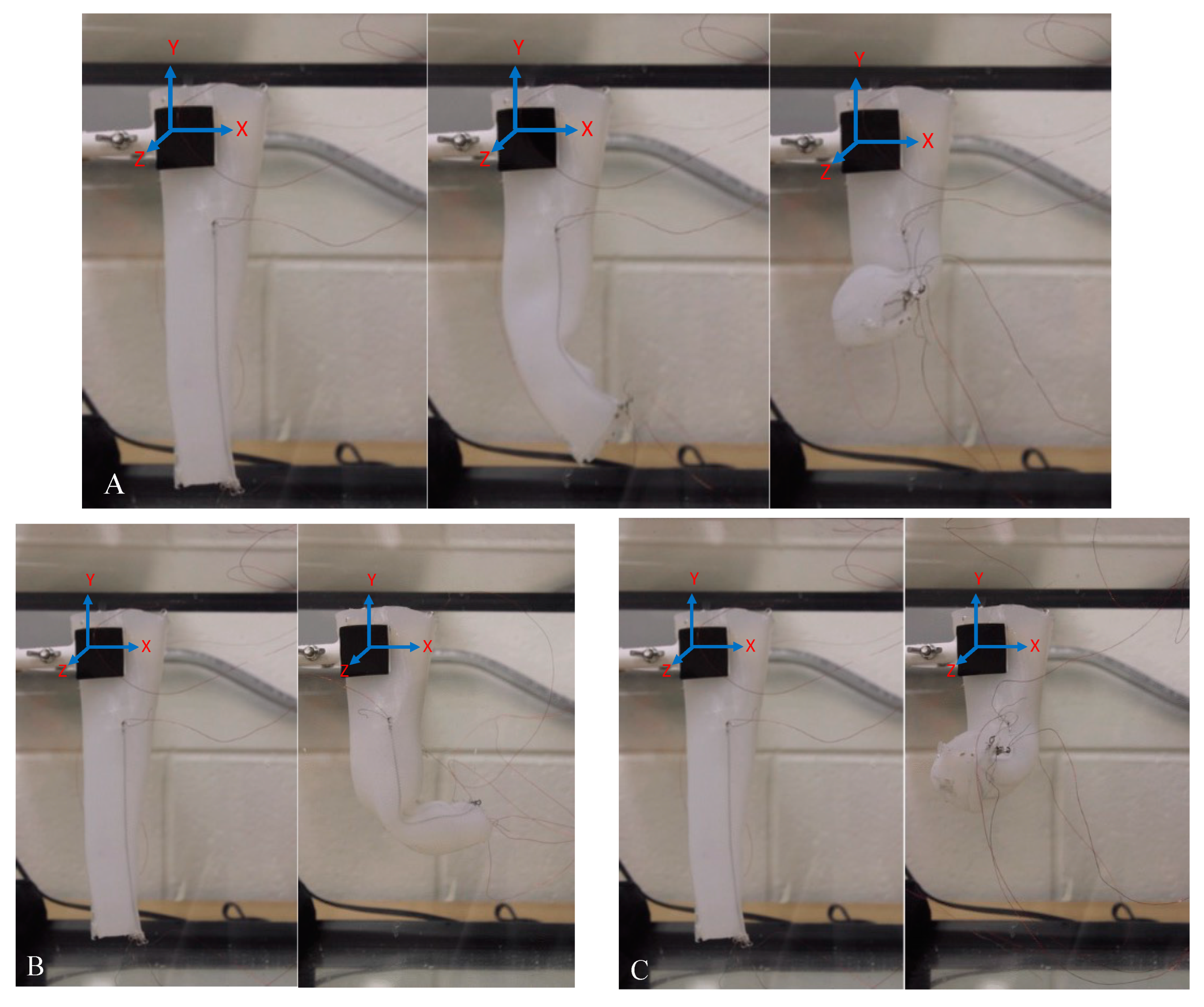
3.5. Grasping and Shape Manipulation of the Arm

Using the created arm, various objects with different sizes and weights were allowed to be grasped by the arm underwater. In these experiments, multiple SMAs were actuated. Figure 11 shows the various objects that the arm was able to lift underwater. It must be noted that the objects had to be held in place for a brief period while the actuation was activated for the arm to be able to hold them. In all the cases shown, the arm was actuated with 2.75 A (total current) for 5 s. The soft material can facilitate delicate grasping without damaging or deforming the structure, as seen in examples of a plant stem and flexible elastomer tubing shown in Figure 12A,F. The soft material of the arm can conform around the body of the object, making it easy to hold on to thicker objects such as a 3D-printed gear and plate in Figure 12B and 12D, respectively, all the way down to thin objects such as a thin ruler shown in Figure 12E. Finally, the use of multiple SMAs increases the weightlifting capability; Figure 12A–H show ascending order by weight of object held starting from 2 g up to 50 g. We can conclude that increasing the number of embedded muscles will further increase the weightlifting capabilities.

3.6. Shape Manipulation Utilizing Sequential Actuation

Shape manipulation was achieved by actuating SMAs in a series of combinations. We observed 2D and 3D bending, as shown in Figure 13. The first was utilizing all 3 embedded SMAs at the same time, the second was for 2 SMAs (long and short), the third was for the opposite 2 SMAs (long and short), and lastly for 2 SMAs (both short). Actuating 3 SMAs at the same time provided 3D bending where the arm initially starts bending in the XY plane and then transfers to the ZY plane. Actuating 2 SMAs (long and short) in the first case resulted in 2D bending in the XY plane, while the third case provided 2D bending in the ZY plane. We observe that, in this case, the bending plane is dependent on the muscle location but both will result in 2D manipulation. Actuating 2 SMAs (both short) results in 2D bending as well. Adding more SMAs will result in a more complex manipulation platform and higher weightlifting capabilities. An integrated control system can be developed to initialize the sequential actuation based on user input.

4. Conclusions and Future Work

In this paper, we have defined the design parameters of a biomimetic octopus-inspired arm actuated by coiled Shape Memory Alloys embedded inside Ecoflex 0010 silicone. Embedding the coiled Shape Memory Alloys gives rise to a curling motion for the whole arm. The strain in the coiled SMA is about 60%, giving rise to the arm achieving a curl throughout the length. The maximum bending angle that is achieved from the fabricated arm is 48°. The arm with one coiled SMA can achieve a maximum bending angle of about 17° when a load of 25 g is attached to the tip of the arm, about 14° when 50 g is attached, and about 10° when a load of 75 g is attached in an underwater environment. To achieve the curling motion and efficiently reach the bending angles mentioned above, a minimum of 140 J of electrical energy is required to be supplied to the arm. Future work is necessary for this robotic system to be deployed into the water for data acquisition. Topics such as continuum robotics, modeling, and simulation of the displacement of the tip of the arm can be implemented in the system. Some design changes to improve the performance of the arm are attainable. If multiple SMA coils with varying lengths are embedded in the silicone that forms the arm, a more controlled and hence better bending can be achieved, and the arm can be designed to have better grasping abilities and achieve more curl. Adding some temperature and vision sensors can improve the system further, which can then be used to grasp objects underwater delicately without causing much disturbance in the ecosystem.

Supplementary Materials

The following supporting information can be downloaded at https://www.mdpi.com/article/10.3390/act12100377/s1, Movie S1: Video showcasing actuation of the arm under described conditions.

Author Contributions

S.D. designed the soft arm, characterized the SMA, integrated the material, and tested the arm in a lab setting. S.D. and Y.A. developed the temperature predictive model. S.D. drafted the paper. Y.A. directed the research and contributed to the technical writing and editing of the manuscript. All authors have read and agreed to the published version of the manuscript.

Funding

This research was funded through an internal faculty startup research fund.

Data Availability Statement

Data are available through request.

Acknowledgments

We would like to thank the department of Mechanical Engineering at Wayne State University, Detroit, Michigan. Without the support of the department, this research work would not have been possible.

Conflicts of Interest

The authors declare no conflict of interest.

References

  1. Tolley, M.T.; Shepherd, R.F.; Galloway, K.C.; Wood, R.J.; Whitesides, G.M. A resilient, untethered soft robot. Soft Robot. 2014, 1, 213–223. [Google Scholar] [CrossRef]
  2. Shintake, J.; Shea, H.; Floreano, D. Biomimetic underwater robots based on dielectric elastomer actuators. In Proceedings of the 2016 IEEE/RSJ International Conference on Intelligent Robots and Systems (IROS), Daejeon, Republic of Korea, 9–14 October 2016; IEEE: New York, NY, USA, 2016; pp. 4957–4962. [Google Scholar]
  3. Calderón, A.A.; Ugalde, J.C.; Zagal, J.C.; Pérez-Arancibia, N.O. Design, fabrication and control of a multi-material-multi-actuator soft robot inspired by burrowing worms. In Proceedings of the 2016 IEEE International Conference on Robotics and Biomimetics (ROBIO), Qingdao, China, 3–7 December 2016; IEEE: New York, NY, USA, 2016; pp. 31–38. [Google Scholar]
  4. Kim, S.; Laschi, C.; Trimmer, B. Soft robotics: A bioinspired evolution in robotics. Trends Biotechnol. 2013, 31, 287–294. [Google Scholar] [CrossRef] [PubMed]
  5. Almubarak, Y.; Punnoose, M.; Maly, N.X.; Hamidi, A.; Tadesse, Y. KryptoJelly: A jellyfish robot with confined, adjustable pre-stress, and easily replaceable shape memory alloy NiTi actuators. Smart Mater. Struct. 2020, 29, 075011. [Google Scholar] [CrossRef]
  6. Almubarak, Y.; Schmutz, M.; Perez, M.; Shah, S.; Tadesse, Y. Kraken: A wirelessly controlled octopus-like hybrid robot utilizing stepper motors and fishing line artificial muscle for grasping underwater. Int. J. Intell. Robot. Appl. 2022, 6, 543–563. [Google Scholar] [CrossRef]
  7. Almubarak, Y.; Tadesse, Y. Twisted and coiled polymer (TCP) muscles embedded in silicone elastomer for use in soft robot. Int. J. Intell. Robot. Appl. 2017, 1, 352–368. [Google Scholar] [CrossRef]
  8. Li, J.; He, J.; Yu, K.; Woźniak, M.; Wei, W. A biomimetic flexible fishtail embedded with shape memory alloy wires. IEEE Access 2019, 7, 166906–166916. [Google Scholar] [CrossRef]
  9. Fan, J.; Du, Q.; Dong, Z.; Zhao, J.; Xu, T. Design of the Jump Mechanism for a Biomimetic Robotic Frog. Biomimetics 2022, 7, 142. [Google Scholar] [CrossRef]
  10. Potnuru, A.; Tadesse, Y. Characterization of coiled SMA actuators for humanoid robot. In Active and Passive Smart Structures and Integrated Systems; SPIE: Bellingham, WA, USA, 2017; pp. 175–184. [Google Scholar]
  11. Hamidi, A.; Almubarak, Y.; Tadesse, Y. Multidirectional 3D-printed functionally graded modular joint actuated by TCPFL muscles for soft robots. Bio-Des. Manuf. 2019, 2, 256–268. [Google Scholar] [CrossRef]
  12. Matharu, P.S.; Gong, P.; Guntaka, K.P.R.; Almubarak, Y.; Jin, Y.; Tadesse, Y.T. Jelly-Z: Swimming performance and analysis of twisted and coiled polymer (TCP) actuated jellyfish soft robot. Sci. Rep. 2023, 13, 11086. [Google Scholar] [CrossRef]
  13. Song, S.-H.; Lee, J.-Y.; Rodrigue, H.; Choi, I.-S.; Kang, Y.J.; Ahn, S.-H. 35 Hz shape memory alloy actuator with bending-twisting mode. Sci. Rep. 2016, 6, 21118. [Google Scholar] [CrossRef]
  14. Hamidi, A.; Almubarak, Y.; Rupawat, Y.M.; Warren, J.; Tadesse, Y. Poly-Saora robotic jellyfish: Swimming underwater by twisted and coiled polymer actuators. Smart Mater. Struct. 2020, 29, 045039. [Google Scholar] [CrossRef]
  15. Haines, C.S.; Lima, M.D.; Li, N.; Spinks, G.M.; Foroughi, J.; Madden, J.D.; Kim, S.H.; Fang, S.; Jung de Andrade, M.; Göktepe, F. Artificial muscles from fishing line and sewing thread. Science 2014, 343, 868–872. [Google Scholar] [CrossRef] [PubMed]
  16. Saharan, L.; de Andrade, M.J.; Saleem, W.; Baughman, R.H.; Tadesse, Y. iGrab: Hand orthosis powered by twisted and coiled polymer muscles. Smart Mater. Struct. 2017, 26, 105048. [Google Scholar] [CrossRef]
  17. Matharu, P.S.; Ghadge, A.A.; Almubarak, Y.; Tadesse, Y. Jelly-Z: Twisted and coiled polymer muscle actuated jellyfish robot for environmental monitoring. Acta IMEKO 2022, 11, 1–7. [Google Scholar] [CrossRef]
  18. Lee, J.-H.; Chung, Y.S.; Rodrigue, H. Long shape memory alloy tendon-based soft robotic actuators and implementation as a soft gripper. Sci. Rep. 2019, 9, 11251. [Google Scholar] [CrossRef]
  19. Deng, E.; Tadesse, Y. A soft 3D-printed robotic hand actuated by coiled SMA. Actuators 2020, 10, 6. [Google Scholar] [CrossRef]
  20. Calisti, M.; Giorelli, M.; Levy, G.; Mazzolai, B.; Hochner, B.; Laschi, C.; Dario, P. An octopus-bioinspired solution to movement and manipulation for soft robots. Bioinspir. Biomim. 2011, 6, 036002. [Google Scholar] [CrossRef]
  21. Arienti, A.; Calisti, M.; Giorgio-Serchi, F.; Laschi, C. PoseiDRONE: Design of a soft-bodied ROV with crawling, swimming and manipulation ability. In Proceedings of the 2013 OCEANS, San Diego, CA, USA, 23–27 September 2013; IEEE: New York, NY, USA, 2013; pp. 1–7. [Google Scholar]
  22. Cianchetti, M.; Calisti, M.; Margheri, L.; Kuba, M.; Laschi, C. Bioinspired locomotion and grasping in water: The soft eight-arm OCTOPUS robot. Bioinspir. Biomim. 2015, 10, 035003. [Google Scholar] [CrossRef]
  23. Laschi, C.; Mazzolai, B.; Mattoli, V.; Cianchetti, M.; Dario, P. Design of a biomimetic robotic octopus arm. Bioinspir. Biomim. 2009, 4, 015006. [Google Scholar] [CrossRef]
  24. Guo, Y.; Liu, L.; Liu, Y.; Leng, J. Review of dielectric elastomer actuators and their applications in soft robots. Adv. Intell. Syst. 2021, 3, 2000282. [Google Scholar] [CrossRef]
  25. Marchese, A.D.; Onal, C.D.; Rus, D. Autonomous soft robotic fish capable of escape maneuvers using fluidic elastomer actuators. Soft Robot. 2014, 1, 75–87. [Google Scholar] [CrossRef] [PubMed]
  26. Cheng, T.; Li, G.; Liang, Y.; Zhang, M.; Liu, B.; Wong, T.-W.; Forman, J.; Chen, M.; Wang, G.; Tao, Y. Untethered soft robotic jellyfish. Smart Mater. Struct. 2018, 28, 015019. [Google Scholar] [CrossRef]
  27. Wehner, M.; Truby, R.L.; Fitzgerald, D.J.; Mosadegh, B.; Whitesides, G.M.; Lewis, J.A.; Wood, R.J. An integrated design and fabrication strategy for entirely soft, autonomous robots. Nature 2016, 536, 451–455. [Google Scholar] [CrossRef]
  28. Joshi, A.; Kulkarni, A.; Tadesse, Y. FludoJelly: Experimental study on jellyfish-like soft robot enabled by soft pneumatic composite (SPC). Robotics 2019, 8, 56. [Google Scholar] [CrossRef]
  29. Shepherd, R.F.; Ilievski, F.; Choi, W.; Morin, S.A.; Stokes, A.A.; Mazzeo, A.D.; Chen, X.; Wang, M.; Whitesides, G.M. Multigait soft robot. Proc. Natl. Acad. Sci. USA 2011, 108, 20400–20403. [Google Scholar] [CrossRef]
  30. Frame, J.; Lopez, N.; Curet, O.; Engeberg, E.D. Thrust force characterization of free-swimming soft robotic jellyfish. Bioinspir. Biomim. 2018, 13, 064001. [Google Scholar] [CrossRef] [PubMed]
  31. Gruber, D.F.; Wood, R.J. Advances and future outlooks in soft robotics for minimally invasive marine biology. Sci. Robot. 2022, 7, eabm6807. [Google Scholar] [CrossRef]
  32. Sfakiotakis, M.; Kazakidi, A.; Tsakiris, D. Octopus-inspired multi-arm robotic swimming. Bioinspir. Biomim. 2015, 10, 035005. [Google Scholar] [CrossRef]
  33. Wu, Q.; Yang, X.; Wu, Y.; Zhou, Z.; Wang, J.; Zhang, B.; Luo, Y.; Chepinskiy, S.A.; Zhilenkov, A.A. A novel underwater bipedal walking soft robot bio-inspired by the coconut octopus. Bioinspir. Biomim. 2021, 16, 046007. [Google Scholar] [CrossRef]
Figure 1. The design of the arm: (A) The conceptual design, (B) The fabricated silicone arm suspended underwater.
Actuators 12 00377 g001
Figure 2. The CAD model of the PLA mold that was created in Fusion 360. The figure shows the schematic of the SMA coil and the slots present in the mold for fixing it.
Actuators 12 00377 g002
Figure 3. The schematic representation of the bending characteristics of the silicone arm embedded with coiled SMA.
Actuators 12 00377 g003
Figure 4. The placement of the origin of the cartesian coordinate system and the demonstration of the bending angle calculations. (A) Nondisplaced arm position. (B) At a fully actuated position.
Actuators 12 00377 g004
Figure 5. Some bending configurations of the silicone arm. (A) Nondisplaced arm. (B) Fully curled arm with no weight attached at the tip. (C) Fully displaced arm lifting 50 g.
Actuators 12 00377 g005
Figure 6. The schematic figure of the experimental setup for measuring the temperature of the embedded SMA coil.
Actuators 12 00377 g006
Figure 7. The plot shows the bending angle (in °) of the tip of the arm vs. the time (in seconds). (A) 2 s heating, (B) 3 s heating, (C) 4 s heating, (D) 5 s heating.
Actuators 12 00377 g007
Figure 8. Maximum bending angle vs. energy consumed by the SMA for various loads.
Actuators 12 00377 g008
Figure 9. A comparison of the maximum bending angle vs. load for single and 3 SMAs embedded in the silicone arm.
Actuators 12 00377 g009
Figure 10. The experimental vs. theoretical temperature for an actuation current of 1.5 A for all the values of heating times.
Actuators 12 00377 g010
Figure 11. The experimental vs. theoretical temperature for a heating time of 5 s, for all the values of current.
Actuators 12 00377 g011
Figure 12. The grasping of objects. (A) a plant (2 g). (B) Small 3D-printed gear (10 g). (C) A plastic syringe (15 g). (D) 3D-printed flat plate (15 g). (E) Thin plastic ruler (15 g). (F) small plastic tube (20 g). (G) Metal spring (40 g). (H) A standard calibrated weight (50 g).
Actuators 12 00377 g012
Figure 13. Snapshots of shape manipulation utilizing sequential actuation. (A) Activating 3 SMAs. (B) 2 SMAs (long middle and the one towards positive Z). (C) 2 SMAs (long middle and the one towards negative Z).
Actuators 12 00377 g013
Table 1. The parameters used for temperature modeling of the SMA coil embedded inside the silicone arm.
QuantityDescriptionValue
T a ? _ Water Temperature17.5 °C
ICurrent1.125 A–1.5 A **
VVoltage18.9 A–23.0 A **
hConvective Heat transfer coefficientObtained semi-analytically, partly through the experiments
AsThe surface area of the coil exposed to the silicone and/or water0.012 m2
mThe mass of the SMA coil by itself0.00228 kg
CpSpecific heat capacity of the SMA + Silicone1620 J/kg/°C
Duty CycleThe ratio of the heating time to cooling time4.2–10% **
Rate of change of temperature per unit timeExtracted Experimentally12.12 °C/s ***
** These parameters are changed with every experiment depending on the used sets of actuations. *** This value is extracted from the heating cycle of the experimentally measured temperatures. All the heating cycles are considered (for all current and time combinations). The rate of change of the temperature over the heating cycle is calculated for all the experiments. The average value of the slopes is calculated and is found to be 12.12.
Table 2. Tabulated values of the energy, voltage, and current are shown, which are plotted in Figure 8.
ItPower DensityVWork = (VIt)Maximum Bending Angle
AseckW/kgVoltsJoules25 g50 g75 g
1.12558.0416.391.712.588.736.25
1.25410.3618.994.514.4310.296.72
1.5315.1323.0103.514.3811.528.47
1.375412.6020.9114.914.0112.289.50
1.25510.8619.8123.815.1811.198.69
1.5415.1323.0138.017.1712.588.26
1.375512.6120.9143.714.5713.8110.28
1.5515.1323.0172.517.0912.889.93
Disclaimer/Publisher’s Note: The statements, opinions and data contained in all publications are solely those of the individual author(s) and contributor(s) and not of MDPI and/or the editor(s). MDPI and/or the editor(s) disclaim responsibility for any injury to people or property resulting from any ideas, methods, instructions or products referred to in the content.

