Article

Design and Implementation of Permanent and Electromagnet Composite Vibration Isolation System Based on Negative Stiffness Theory

College of Intelligence Science and Technology, National University of Defense Technology, Changsha 410073, China
*
Author to whom correspondence should be addressed.
Actuators 2023, 12(1), 44; https://doi.org/10.3390/act12010044
Submission received: 29 November 2022 / Revised: 21 December 2022 / Accepted: 4 January 2023 / Published: 16 January 2023
(This article belongs to the Special Issue Advanced Theory and Application of Magnetic Actuators)

Abstract

:
In order to decrease the transmission of vibration and achieve the attenuation of the vibration magnitude of an isolated object, a new type of permanent and electromagnet composite vibration isolation system is designed based on negative stiffness theory. Firstly, according to the characteristic analysis, the design of a permanent and electromagnet hybrid actuator is accomplished; secondly, the vibration isolation system model is established, and the active control strategy based on the fuzzy PID algorithm is designed. Finally, a test platform is built to verify the vibration isolation effect. The results indicate that the developed permanent and electromagnet composite vibration isolation system renders the sharp attenuation of external vibration in multiple frequency bands. When the external vibration frequency is within the frequency range of 20 Hz to 100 Hz, the vibration attenuation is greater than 80%; when the external vibration frequency is within the frequency range of 100 Hz to 500 Hz, the vibration attenuation rate is greater than 90%.

1. Introduction

Vibration, which is a critical bottleneck restricting accuracy and performance, runs through the entire life cycle of weapons and equipment. Additionally, it also seriously affects the reliability of equipment and reduces normal service life [1,2,3,4]. In order to decrease the transmission of vibration and realize the vibration level attenuation of the object to be isolated, various vibration isolation systems and vibration control technologies have emerged. In recent years, research of negative stiffness technology has become a focus in the field of vibration isolation. Saitama University in Japan proposed a three-degrees-of-freedom modular vibration isolation system based on springs and ferromagnetic materials which can realize the dynamic adjustment of negative stiffness and has a noticeable vibration isolation effect on the disturbance of the load [5,6]. The Naval Engineering University designed a positive and negative stiffness parallel active and passive vibration isolation controller to be applied to ships. Permanent and electromagnet hybrid actuators are used in the air spring for significant vibration isolation [7,8,9].
In order to reduce the damage of external vibration to a certain type of equipment, this paper studies and designs a new type of permanent and electromagnet composite vibration isolation system (PECVIS) based on the negative stiffness theory, taking permanent magnets as negative stiffness components. This system can dynamically adjust the stiffness and damping of the system to achieve sharp attenuation of external vibration in multiple frequency bands.

2. Design of PECVIS Based on Negative Stiffness Theory

The stiffness of the traditional vibration isolation device is positive. Hence, there is a contradiction between the system stiffness, the vibration isolation effect and the carrying capacity. What accounts for it is that the greater the force of the positive stiffness element, the greater the deformation. On the contrary, the negative stiffness element is less than zero, and the direction of the force increment is opposite to that of the deformation increment [10,11,12,13,14]. Adding negative stiffness components to the traditional vibration isolation device can effectively decrease the overall stiffness of the system without damaging the bearing capacity of the system and efficiently resolve the conflicts of the traditional passive vibration isolation system, as well as achieve a relatively better low-frequency vibration isolation effect [15,16,17]. Therefore, based on the negative stiffness theory, a new type of PECVIS is designed in this paper. The overall structure of the PECVIS is illustrated in Figure 1.
The mechanical spring provides the support force for the vibration-isolated object through pre-compression. Under the condition of no current, the vibration-isolated object is always near the initial balance position by balancing the electromagnetic attraction between the permanent and electromagnet hybrid actuator and the armature. In the permanent and electromagnet hybrid actuator, the permanent magnet is mainly used to provide negative stiffness, reduce or balance the positive stiffness of the system brought by the mechanical spring and then make the total stiffness of the system reach the quasi-zero-stiffness state near the balance point. The electromagnet in the permanent and electromagnet hybrid actuator can change the magnetic field strength of the permanent and electromagnet hybrid actuator by changing the size and direction of the voltage and current and finally achieve the goal of dynamically adjusting the electromagnetic attraction. The directions of the electromagnetic attraction force, support force and gravity have been marked in Figure 1.
The designed PECVIS in this paper can not only reduce the total stiffness of the system through permanent magnets, but also dynamically adjust the equivalent stiffness and equivalent damping of the system. Therefore, the designed PECVIS is able to achieve a good low-frequency vibration isolation effect and broaden the vibration isolation frequency band.
The PECVIS is designed according to modularization, which is divided into two parts: the passive vibration isolation device and the permanent and electromagnet hybrid actuator.

2.1. Design of Passive Vibration Isolation Device

The selected springs need high strength and good performance so as to meet the design requirements. Therefore, the equal-pitch cylindrical coil spring is selected, which can not only simplify the design of the vibration isolation system but can also achieve excellent passive vibration isolation function. There are four mechanical springs in the whole vibration isolation system, and their installation positions are shown in Figure 2.
The spring material utilized in this paper is carbon spring steel wire with a grade of 65 Mn, and its specific parameters are shown in Table 1.

2.2. Design of Electromagnet for Permanent and Electromagnet Hybrid Actuator

The electromagnet is the active control module of the permanent and electromagnet hybrid actuator, as well as the active vibration isolation device. This module changes the input current of the electromagnet by controlling the voltage of the electromagnet, thus, changing the magnetic field strength of the permanent and electromagnet hybrid actuator and achieving the goal of dynamically adjusting the attraction force.
According to experience of electromagnet design and installation, the E-type electromagnet has a good spatial structure which is highly in line with the design requirements of the PECVIS. Therefore, the spatial structure of the electromagnet is designed as an E-type electromagnet, as shown in Figure 3. Given that the electromagnet faces different vibration environments and heat problems, the silicon steel disc of model EI-180 is used as the core and armature of the electromagnet. The enameled copper round wire with low resistance is made into the coil of the electromagnet. The attraction of the E-type electromagnet is proportional to the pole area of the iron core. The larger the pole area of the iron core, the stronger the attraction of the E-type electromagnet. However, due to the requirements of the installation space of the E-type electromagnet, the pole surface of the middle iron core is square, that is, the length and width is 60 mm, respectively. The pole surfaces of the left and right iron cores are the same rectangle, and the length and width are 60 mm and 30 mm, respectively.
The armature is bolted to the bottom of the load platform. The armature is made of silicon steel discs. The length, width and height of the armature are 180 mm, 60 mm and 30 mm, respectively.

2.3. Design of Permanent Magnet for Permanent and Electromagnet Hybrid Actuator

The design of a permanent magnet mainly includes the selection of material, the geometric parameters and the analysis of the attraction force. Considering the extraordinary energy density, great coercivity and magnetic energy product of NdFeB materials, the permanent and electromagnet hybrid actuator designed in this paper selects N35 NdFeB material. The specific parameters are shown in Table 2.
The permanent magnet is assembled on the upper end of the electromagnet core, the thickness of which directly determines the magnitude of its attraction force. Considering that lots of factors are often ignored in theoretical calculation, this paper uses the finite element analysis method to numerically simulate the electromagnetic field of the permanent and electromagnet hybrid actuator. As shown in Figure 4, a three-dimensional finite element model is established by Maxwell software, and the attraction force generated by the permanent magnet is numerically calculated and analyzed. According to the different thicknesses of the permanent magnets in the permanent and electromagnet hybrid actuator, the numerical analysis of the force is carried out, and the calculation results are shown in Table 3. The magnetic flux density of the permanent and electromagnet hybrid actuator is shown in Figure 5.
The stiffness of the passive vibration isolation device composed of the spring is k s = 86.461 N / mm . As a negative stiffness element, the permanent magnet needs to enable the whole system to work normally under the circumstances of nearly zero stiffness; so, the stiffness of the permanent magnet should be approximately 86.461 N / mm . This means that the permanent magnet is required to produce an attraction force of 600 N.
Since the air gap between the permanent magnet and the armature does not vary significantly, it is considered that the attraction force of the permanent magnet changes linearly near the working point. Therefore, the stiffness of the permanent magnet can be calculated between the 9.5 mm and 10.5 mm air gaps. The stiffness of the permanent magnet is:
k m = F m 10.5 F m 9.5 Δ z = 84.4 N / mm
Based on the above analysis, the optimal thickness of the permanent magnet is determined to be 10 mm. The overall stiffness of the PECVIS can be approximated as:
k = k s k m = 2.061 N / mm
By reasonably designing the size of the permanent magnet, the positive and negative stiffness near the equilibrium point is roughly equal, and the total stiffness tends to be zero, reaching a quasi-zero-stiffness state.

3. Modeling and Nominal Controller Design of PECVIS

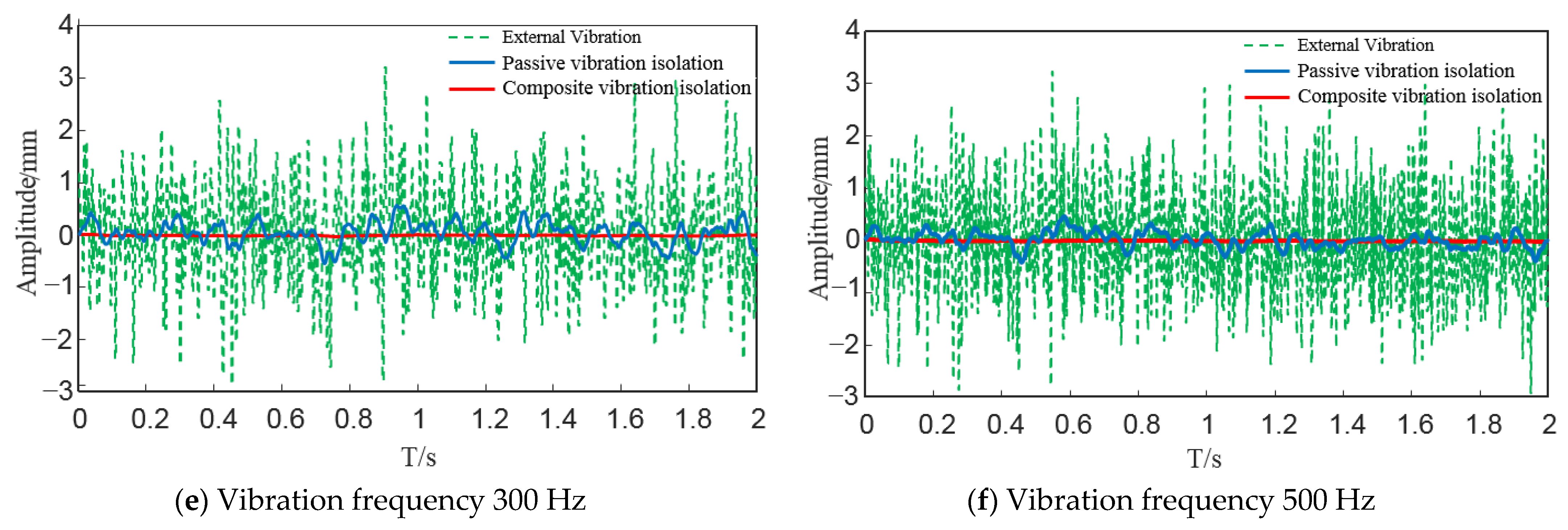
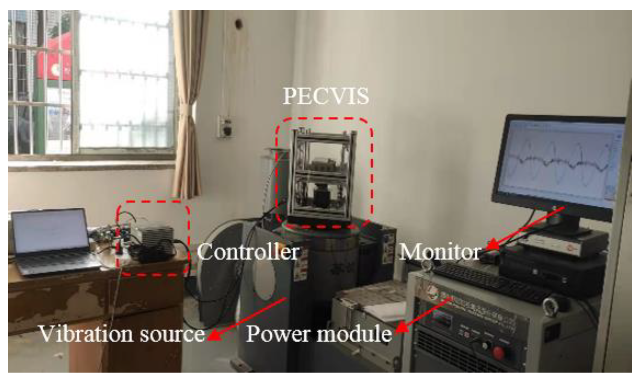
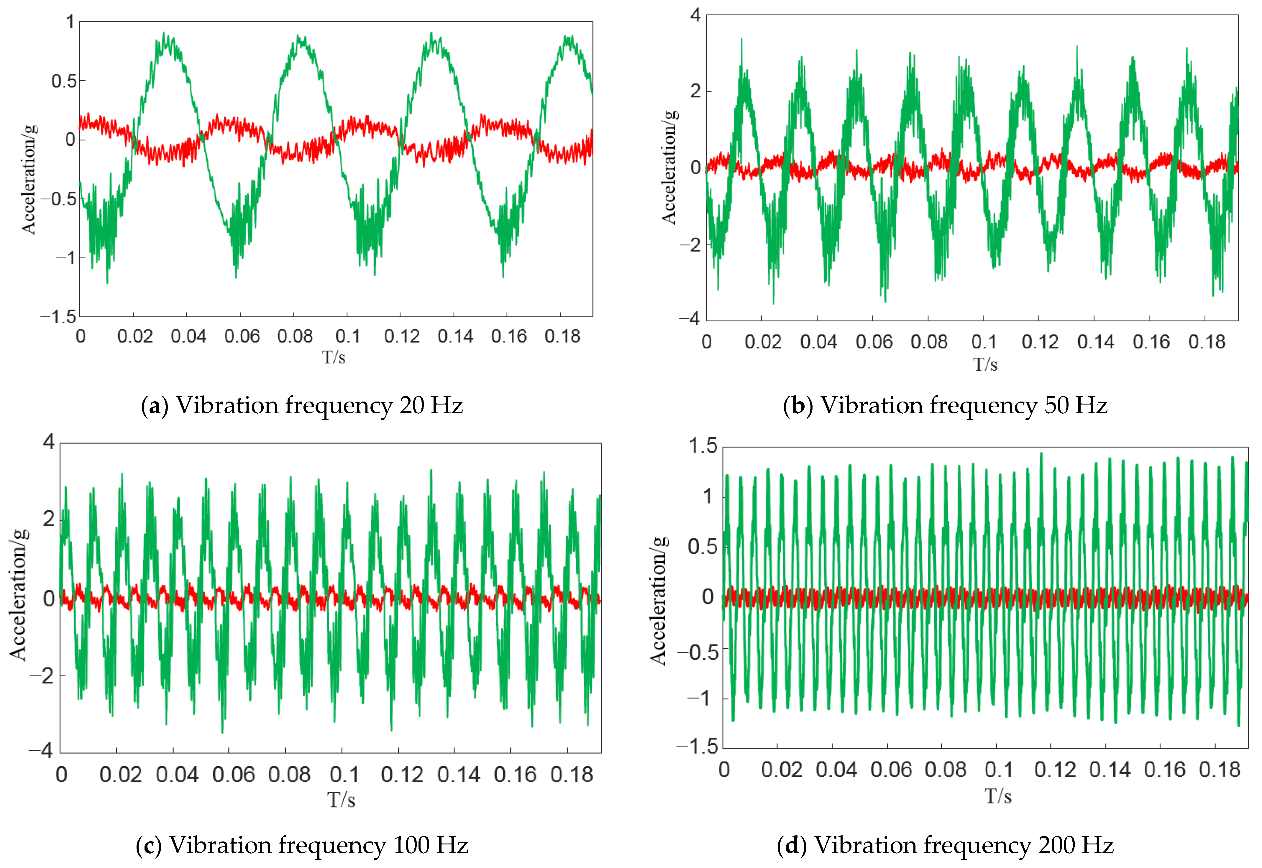
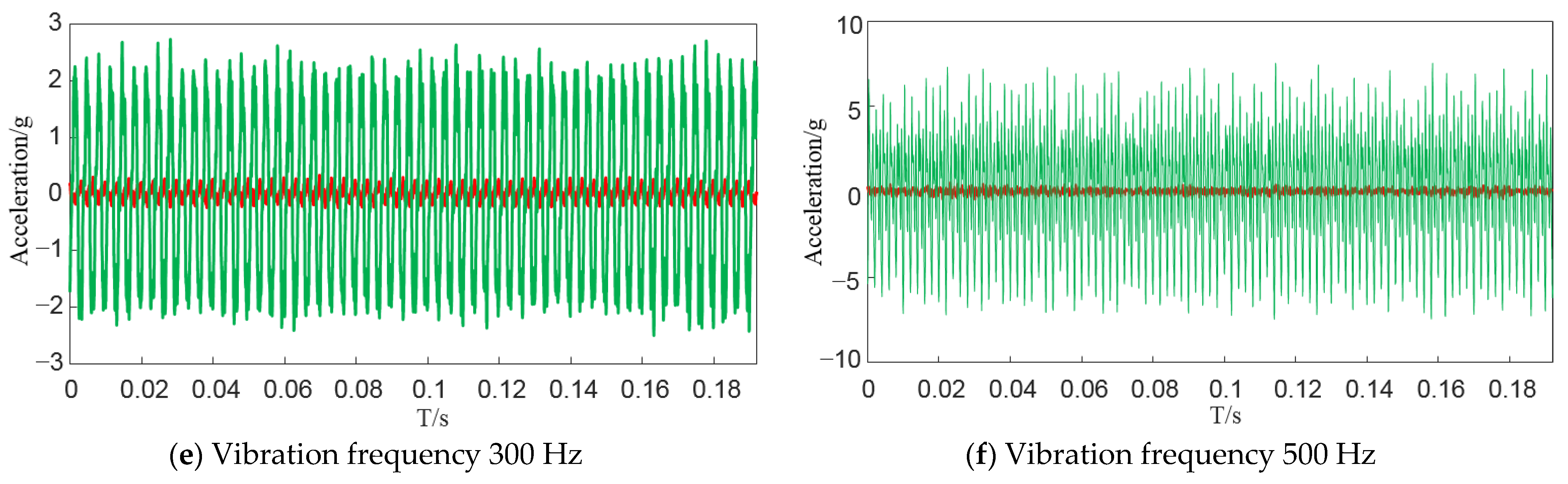
In order to dynamically adjust the stiffness and damping of the system, combined with the dynamic characteristics of the permanent and electromagnet hybrid actuator, the model of the PECVIS is established, and the nominal controller is designed.

3.1. Modeling of PECVIS

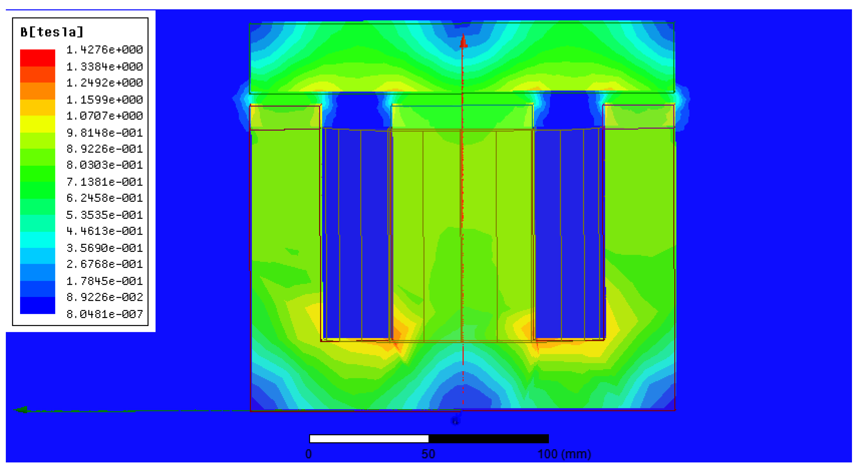
As to the complex electromechanical system of the PECVIS, many factors are ignored in order to reduce the difficulty of solving problems [18,
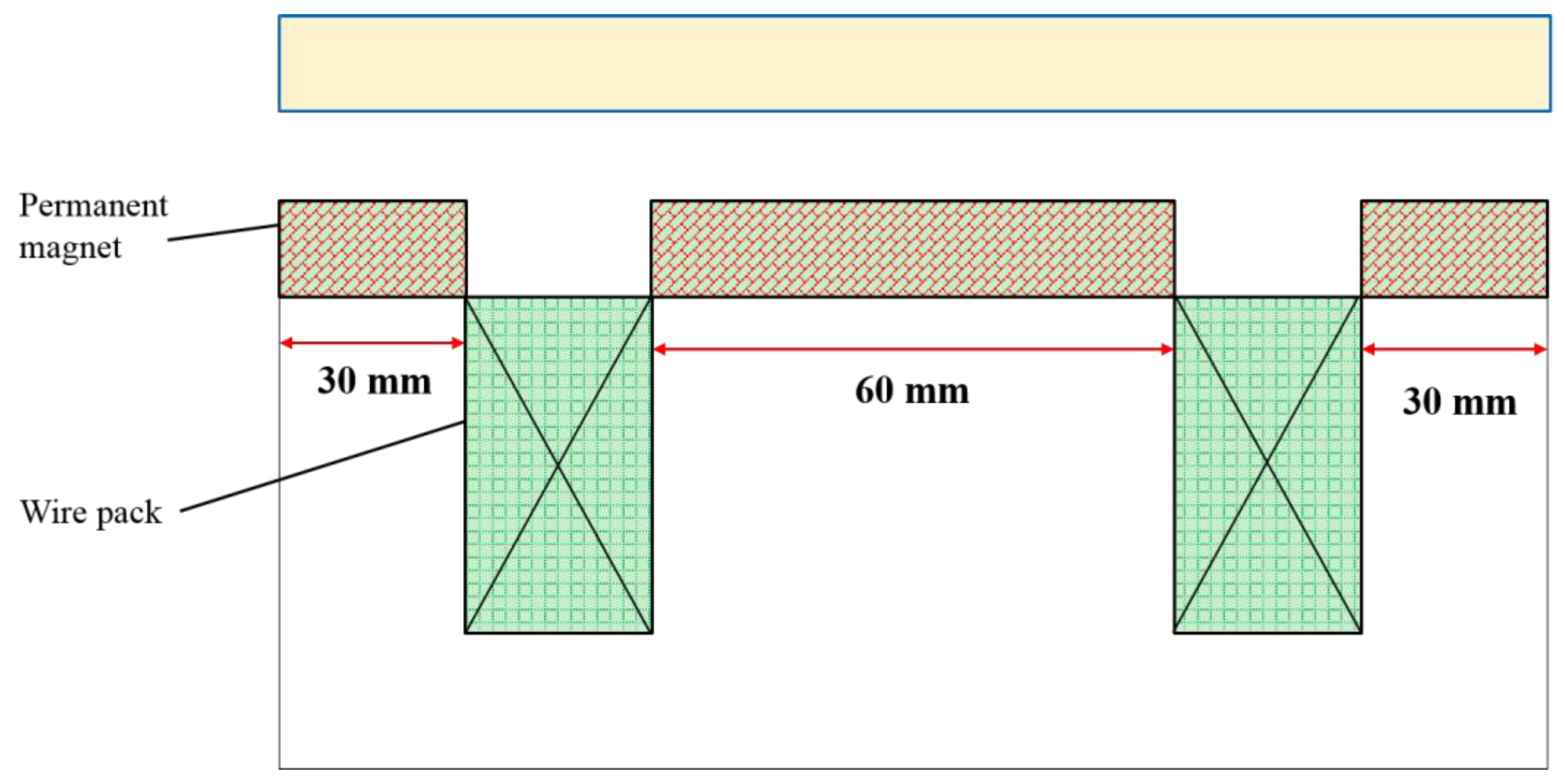
19]. The magnetic flux leakage and edge effects are also ignored in this study, and it is considered that the intensity distribution of the permanent magnetic–electromagnetic hybrid magnetic field is uniform. According to the theory of the permanent magnet electromagnetic hybrid magnetic field, the equivalent magnetic circuit of the permanent and electromagnet hybrid actuator is shown in Figure 5.
According to Ohm’s law, the entire circuit satisfies the following relationship:
{ N i + H c z m R m 1 Φ 1 R m 2 Φ 2 + H c z m = 0 N i + H c z m R m 1 Φ 1 R m 3 Φ 3 + H c z m = 0
In the formula, N . is the number of turns of the electromagnetic coil, i is the current passing through the coil of the electromagnet, H c is the coercive force of the NdFeB permanent magnet, z m is the thickness of the permanent magnet, and Φ 1 is the magnetic flux of the intermediate magnetic circuit of the E-type electromagnet. In addition, Φ 2 and Φ 3 are the magnetic fluxes of the left and right magnetic circuits, respectively, R m 1 is the total magnetic resistance of the middle air gap and permanent magnet, R m 2 is the total magnetic resistance of the left air gap and permanent magnet and R m 3 is the total magnetic resistance of the right air gap and permanent magnet.
The magnetic flux of the middle magnetic circuit of the E-type electromagnet is:
Φ 1 = 2 Φ 2 = ( N i + 2 H c z m ) μ 0 μ r s 1 2 ( z m + z μ r )
In this formula, μ 0 and μ r are the vacuum permeability and the relative permeability of NdFeB permanent magnet respectively, s 1 is the magnetic pole area of the middle permanent magnet and z is the gap between the permanent magnet and the armature.
The magnetic force generated by the permanent and electromagnet hybrid actuator is:
F m = Φ 1 2 μ 0 s 1 + Φ 2 2 μ 0 s 2 + Φ 3 2 μ 0 s 3 = ( N i + 2 H c z m ) 2 μ 0 μ r 2 s 1 2 ( z μ r + z m ) 2
In the formula, F m is the magnetic force generated by the permanent and electromagnet hybrid actuator, s 2 is the magnetic pole area of the upper surface of the left permanent magnet and s 3 is the magnetic pole area of the upper surface of the right permanent magnet.
The relationship between the electromagnetic attraction force generated by the permanent and electromagnet hybrid actuator and the current and air gap can also be listed in the following form:
F m = α ( β i + 1 ) 2 ( z + λ ) 2
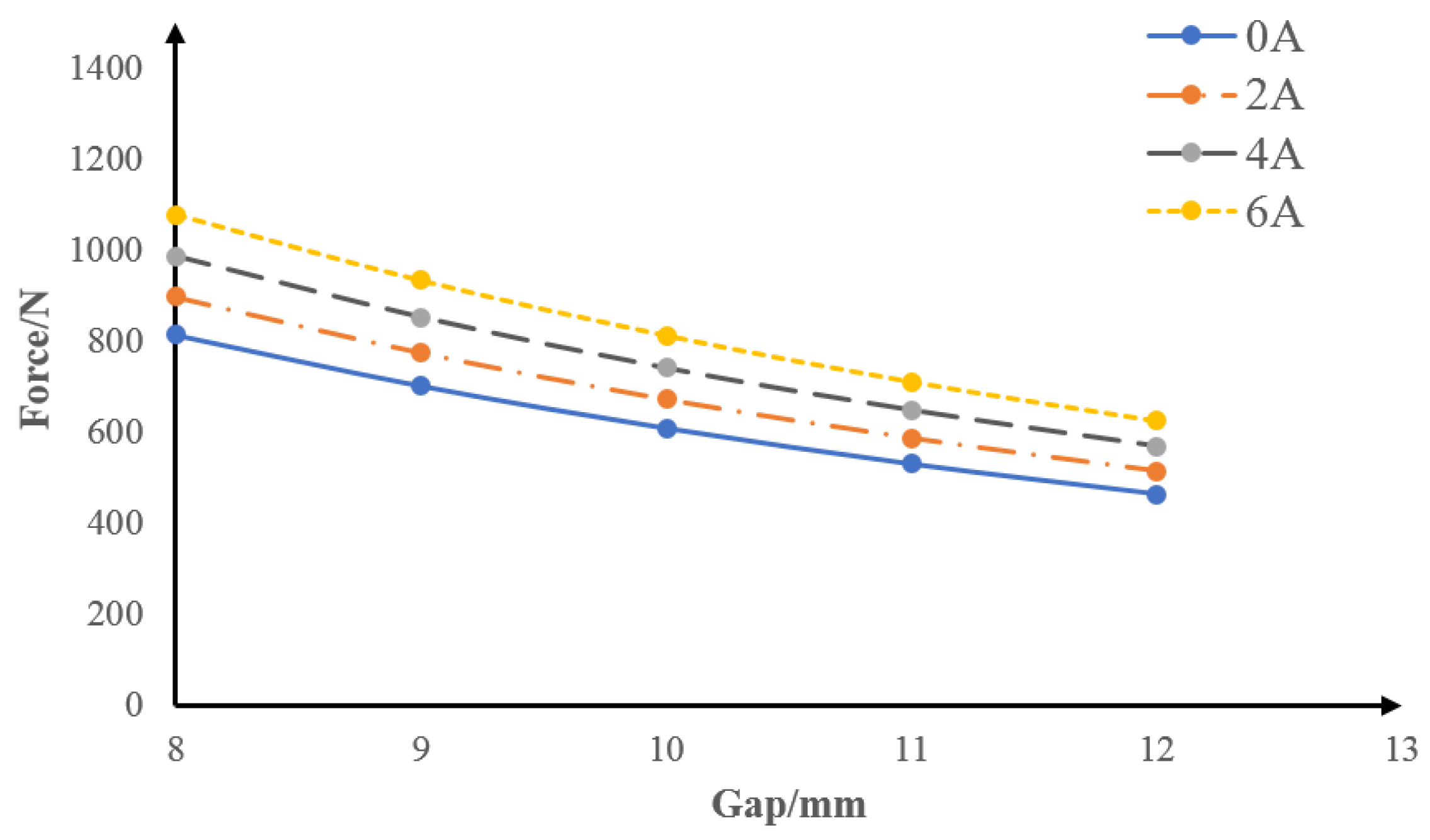
The specific values of α , β and λ are fitted by the numerical results of the electromagnetic attraction force. The electromagnetic attraction force generated by the permanent and electromagnet hybrid actuator under different currents and different air gaps is shown in Table 4.
According to the above Table 4, the relationship between electromagnetic attraction force and the gap is as shown in Figure 6.
According to the above table, the following is obtained:
α = 131500 , β = 0.02574 , λ = 4.696
The electromagnet is an inductive element, so the relationship between its voltage and current is:
u = R i + N 2 μ 0 μ r s 1 2 ( z μ r + z m ) d i d t N ( N i + 2 H c z m ) μ 0 μ r 2 s 1 2 ( z μ r + z m ) 2 d z d t
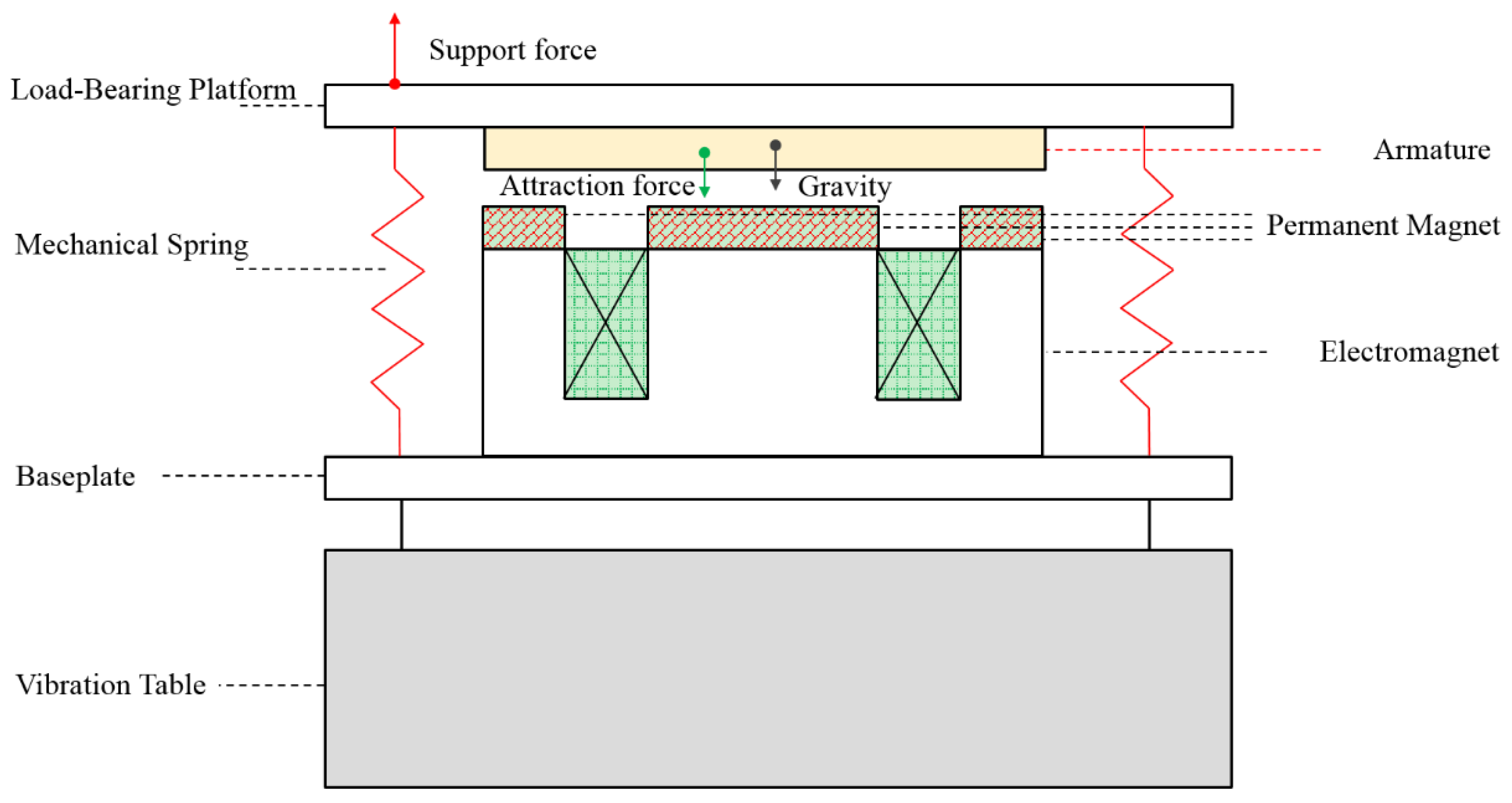
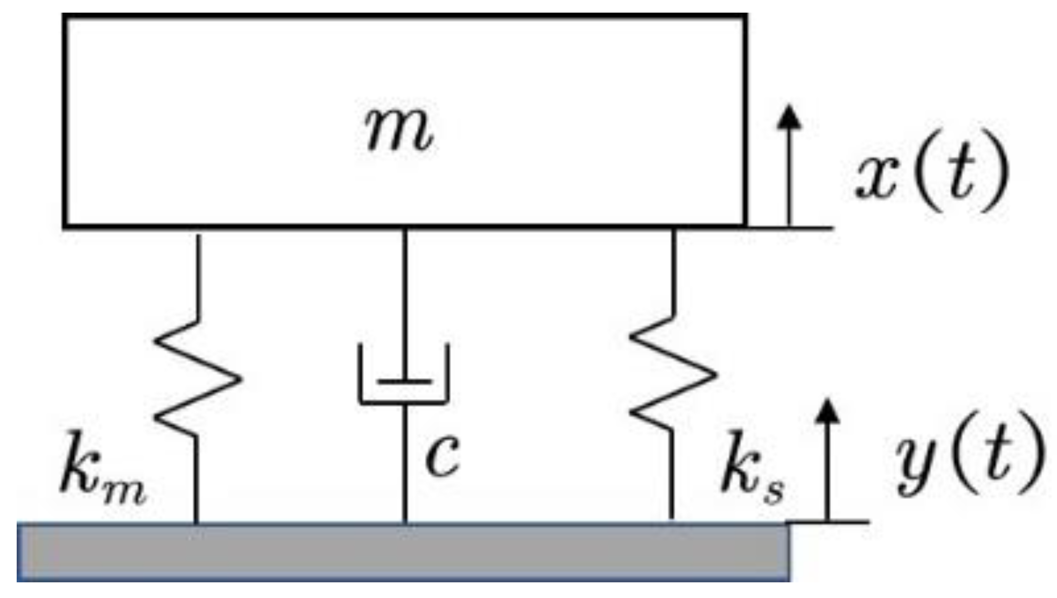
The schematic diagram of the model of the PECVIS is shown in Figure 7. k s and c represent the stiffness and damping of the spring, respectively, and k m represents the stiffness of the permanent magnet–electromagnetic hybrid actuator, which includes the negative stiffness caused by the permanent magnet and the variable stiffness caused by the electromagnet.
Taking the vertical upward as the positive direction, the external excitation y ( t ) forces the vibration-isolated object of the system to vibrate in the vertical direction. x ( t ) is the vibration.
The dynamic model of the system can be expressed as:
m d 2 x d t 2 = k s ( y x + Δ l ) + c ( d y d t d x d t ) m g F m
where Δ l is the compression amount of the spring at the equilibrium point.
The system parameter values are referred to in Table 5.

3.2. Design of Nominal Controller

Given that the working point of the PECVIS is stable, and the operating range is concentrated around the working point, the linear analysis method can be used to analyze the systems. It is assumed that, when the system is static, the initial distance z 0 satisfies:
z = z 0 y + x
Taking the state variables X = [ X 1 X 2 X 3 ] = [ x x ˙ i ] , the linearized model is:
{ X ˙ 1 = X 2 X ˙ 2 = ( k s m 2 α ( β i 0 + 1 ) 2 m ( z 0 + λ ) 3 ) ( y X 1 ) + c ( y ˙ X 2 ) m 2 α β ( β i 0 + 1 ) m ( z 0 + λ ) 2 X 3 X ˙ 3 = 2 ( z 0 μ r + z m ) N 2 μ 0 μ r s 1 ( u R X 3 )
Taking the input variable U = [ y y ˙ u ] , the output variable of the system is Y = x . Then, the system model can be represented by the following state-space equation:
X ˙ = [ 0 1 0 k s m + 2 α ( β i 0 + 1 ) 2 m ( z 0 + λ ) 3 c m 2 α β ( β i 0 + 1 ) m ( z 0 + λ ) 2 0 0 2 ( z 0 μ r + z m ) N 2 μ 0 μ r s 1 R ] X + [ 0 0 0 k s m 2 α ( β u 0 + 1 ) 2 m ( z 0 + λ ) 3 c m 0 0 0 2 ( z 0 μ r + z m ) N 2 μ 0 μ r s 1 ] U
The characteristic polynomial of the PECVIS does not satisfy the Hurwitz stability criterion. According to the Hartman–Grobman theorem, the system is unstable. Further analysis of the controllability of the system shows that the controllability matrix rank of the system is 3, so the PECVIS is completely controllable.
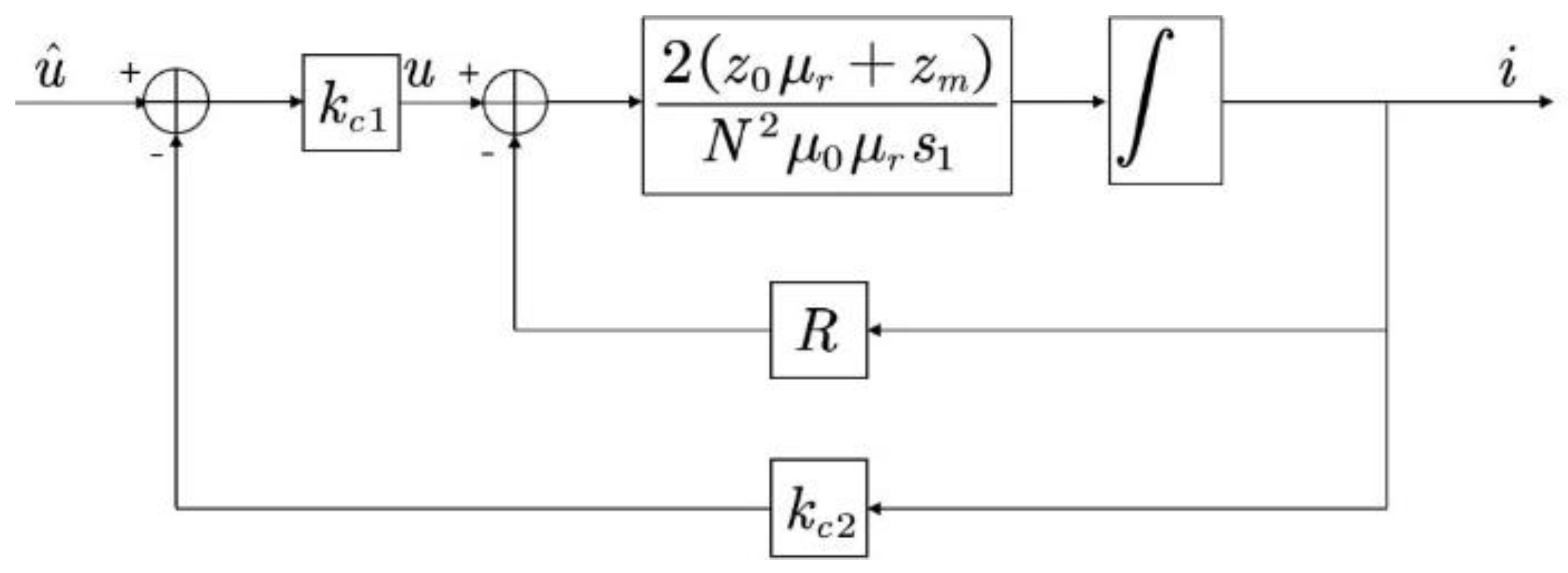
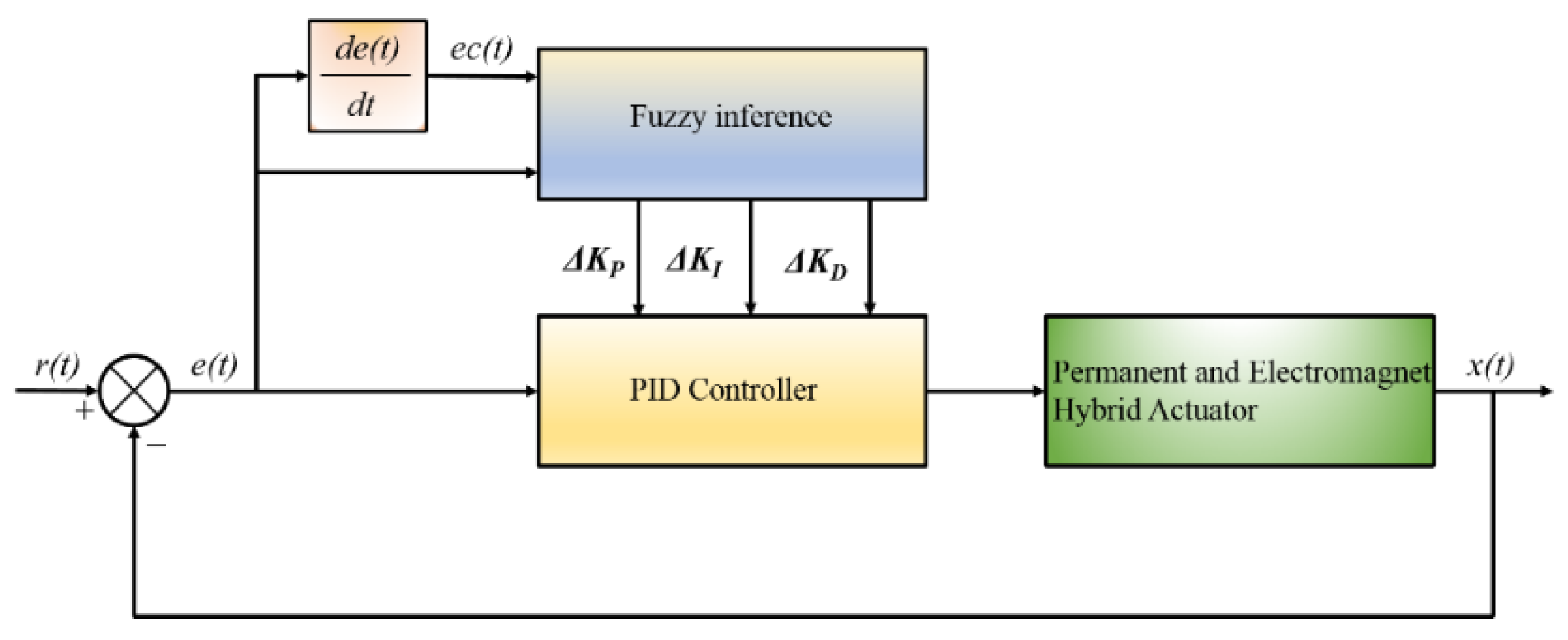
Based on the thought of cascade control, the control algorithm is usually divided into two parts, including the inner loop (also called the current loop) and the outer loop (also called the position loop) [20,21,22]. When the electromagnet works in the equilibrium position, due to the small variation range of inductance, its inductance can be considered as a constant. Therefore, close to the operating point, the transfer function of the relationship between the voltage and the current of the levitating electromagnet is:
G i ( s ) = i ( s ) u ( s ) = 1 R N 2 μ 0 μ r s 1 2 R ( z 0 μ r + z m ) s + 1
The transfer functions of the electromagnet voltage and current show that the electromagnet is a typical inertial link, and the response speed of the output current seriously lags behind the changing speed of the input voltage. Therefore, current negative feedback is introduced in the design of the control algorithm. k c 1 is the preamplification factor, and k c 2 is the negative feedback coefficient, as shown in Figure 8.
The input voltage before the introduction of current feedback is u ^ , then the voltage directly acting on the electromagnet is:
u = k c 1 ( u ^ k c 2 i )
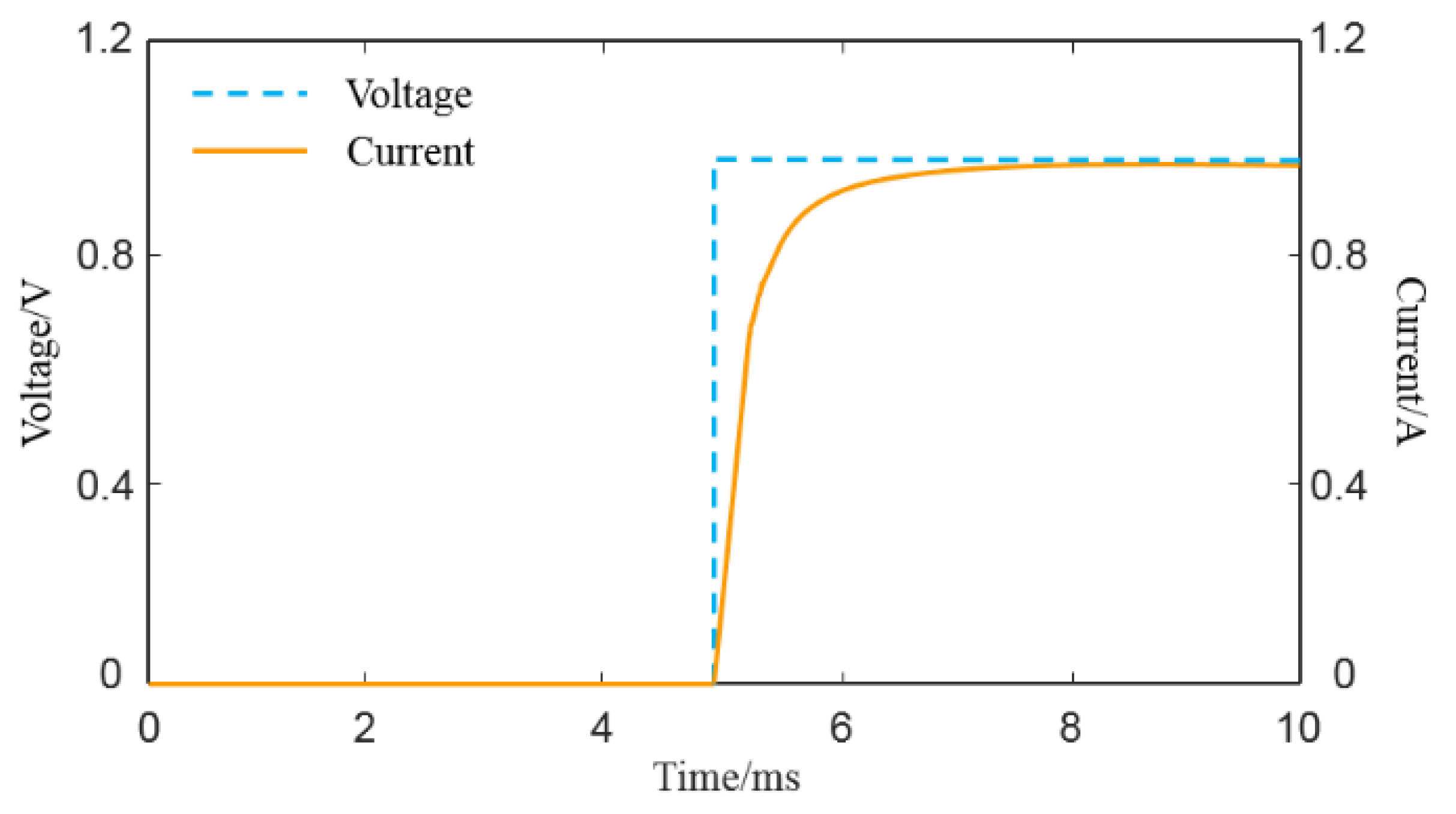
When the input voltage is a unit step signal, the response curve after introducing the current loop is as shown in Figure 9.
After introducing the current negative feedback, the output current can track the change of the input voltage in time, and the order of the system is decreased from 3 to 2. After the design of the current loop is completed, the design of the position loop adopts the PID control algorithm:
u ( t ) = K P e ( t ) + K I 0 t e ( t ) d t + K D d e ( t ) d t
where K p is the proportional coefficient, K I is the integral coefficient and K D is the differential coefficient. In the PECVIS, the e ( t ) deviation is the displacement x ( t ) of the vibration-isolated object in the vertical direction. Initially, the vibration-isolated object is at the equilibrium point, and its initial value is x 0 = 0 . Therefore, the PID control law of the system is:
u ( t ) = ( K P x ( t ) + K I 0 t x ( t ) d t + K D d x ( t ) d t )
In summary, after the control law design is completed, it is brought into the PECVIS, which satisfies:
m d 2 x d t 2 = ( k s 2 α ( β u 0 + 1 ) 2 ( z 0 + λ ) 3 ) ( y x ) + c ( y ˙ x ˙ ) + 2 α β ( β u 0 + 1 ) m ( z 0 + λ ) 2 ( K P x + K I 0 t x d t + K D d x d t )
At this time, the equivalent stiffness and equivalent damping of the PECVIS are:
k ˜ = k s 2 α ( β u 0 + 1 ) 2 ( z 0 + λ ) 3 2 α β K P ( β u 0 + 1 ) m ( z 0 + λ ) 2
c ˜ = c 2 α β K D ( β u 0 + 1 ) m ( z 0 + λ ) 2
The PECVIS designed in this paper can realize the dynamic adjustment of the stiffness and damping of the system by adjusting the three parameters K p , K I and K D .

4. Active Control Strategy Based on Fuzzy PID Algorithm

In order to realize the vibration attenuation of the isolated object in multi-frequency bands, it is necessary to complete the dynamic adjustment and control parameter optimization of the existing nominal controller. Therefore, this paper adopts the fuzzy PID algorithm, takes the error e and the error variation ec as the input signals of the input fuzzification module and uses the fuzzy rules and the defuzzification process to automatically update the correction values Δ K P , Δ K I and Δ K D in real time. The block diagram of fuzzy PID controller is shown in in Figure 10.

4.1. Determining Input and Output Variables

The vibration system analysis determines e and ec controller output Δ K P , Δ K I and Δ K D and then the one-to-one mapping relationship with fuzzy domain is established according to this value range [23,24,25,26]. Table 6 is the parameter table of the established fuzzy controller.

4.2. Select Membership Function

In fuzzy control, the size of input and output variables is usually described by human experience [27,28]. The three levels of description are usually ‘big’, ‘middle’ and ‘small’, and the positive and negative direction and zero state are added so there are seven levels to describe the size of input and output variables in total. Therefore, the fuzzy subset of input and output variables is taken as ‘positive big (PB)’, ‘positive middle (PM)’, ‘positive small (PS)’, ‘zero state (ZE)’, ‘negative small (NS)’, ‘negative middle (NM)’ or ‘negative large (NL)’. Secondly, the input and output variables are fuzzified to determine the membership degree. In this paper, the Gaussian membership function is used to calculate the membership of input and output variables, as shown in Figure 11.

4.3. Fuzzy Reasoning

The fuzzy reasoning process is built on fuzzy rules, and the establishment of fuzzy rules is based on vibration characteristics. The principle of Δ K P , Δ K I and Δ K D setting is shown in Table 7, Table 8 and Table 9.

4.4. Defuzzification

The maximum membership method and the weighted average method are the most commonly used defuzzification methods. The weighted average method calculates multiple membership degrees through a parameter and regards the membership degree as the weight coefficient multiplied by the value of the degree. The fuzzy domain value of the output variables is able to become the actual outputs Δ K P , Δ K I and Δ K D . Based on the above fuzzy PID rules, the active control strategy based on fuzzy PID control is designed.

5. Simulation Verification

The model of the system is built by Simulink, and the designed active control strategy based on the fuzzy PID algorithm is substituted into the model shown in Figure 12 for simulation verification.
When the external vibration frequency is 20 Hz, 50 Hz, 100 Hz, 200 Hz, 300 Hz and 500 Hz, the results are as presented in Figure 13.
As shown in Figure 14, the green curve is the external random vibration, the blue curve is the isolated object vibration only caused by the passive vibration isolation system and the red curve is the isolated object of the PECVIS. In order to evaluate the vibration isolation ability of the PECVIS, the vibration attenuation rate of the system is calculated with the different external vibration frequencies, as shown in Table 10. The attenuation rate of the designed PECVIS for a 20–50 Hz external random vibration is greater than 86.5% and, for a 100–500 Hz external random vibration, is greater than 95%. The simulation results show that the designed PECVIS achieves a good low-frequency vibration isolation effect and broadens the vibration isolation frequency band.

6. Realization and Testing of PECVIS

A PECVIS test platform is built, which is used to test the vibration isolation effect of the PECVIS.

6.1. The Construction of the Test Platform of PECVIS

This paper uses the Baseline series real-time target machine from Speedgoat to develop the controller of the PECVIS.
Considering that the vibration-isolated object is in the process of vibration, the displacement sensor adopts the non-contact TR81 series sensor, and the acceleration sensor adopts the YA23-type ICP high-sensitivity acceleration sensor. The Sushi DC-600-6 vibration table is selected as the external vibration source device to carry out the test of the PECVIS in this paper. The test site is presented in Figure 14.

6.2. Vibration Isolation Tests

In the actual experiment process, the vibration table can only provide a pseudo-sinusoidal random vibration excitation source at present. For the vibration isolation requirements of multiple frequency bands, the same external vibration frequency setting as the simulation is used to verify the vibration isolation effect. The vibration table set the vibration frequency to 20 Hz, 50 Hz, 100 Hz, 200 Hz, 300 Hz and 500 Hz and the maximum amplitude to 2.5 mm. The vibration isolation effect is illustrated in Figure 15, where the red and green curves correspond to the vibration acceleration of the isolated object and the external vibration, respectively.
The vibration attenuation rate and vibration transmissibility of the system are calculated with the vibration level difference method to evaluate the vibration isolation ability of the PECVIS. The vibration attenuation rate and vibration transmissibility of the PECVIS at frequencies of 20 Hz, 50 Hz, 100 Hz, 200 Hz, 300 Hz and 500 Hz are shown in Table 11.

7. Conclusions

In this paper, a permanent and electromagnet composite vibration isolation system is designed based on negative stiffness theory. The mathematical model of the PECVIS is established, and an active control strategy based on the fuzzy PID algorithm is designed to dynamically adjust the stiffness and damping of the PECVIS successfully. A test platform is built to verify the vibration isolation effect. The results indicate that the PECVIS is able to decrease the transmission of vibration and achieve the attenuation of the vibration magnitude of the isolated object. The designed vibration isolation system has a vibration attenuation rate of 83.64% when the external vibration frequency is 20 Hz; the vibration attenuation rate is 91.91% at 50 Hz; the vibration attenuation rate is 90.55% at 100 Hz; the vibration attenuation rate is 92.60% at 200 Hz; the vibration attenuation rate is 93.52% at 300 Hz; and the vibration attenuation rate is 95.35% at 500 Hz.
The study demonstrates that the designed PECVIS can not only reduce the total stiffness of the system through permanent magnets, but also dynamically adjust the equivalent stiffness and equivalent damping of the system. Meanwhile, the designed PECVIS is able to achieve a good low-frequency vibration isolation effect and broaden the vibration isolation frequency band.

Author Contributions

Conceptualization, M.Z. and X.L.; methodology, M.Z. and B.Z. software, B.Z.; validation, M.Z., B.Z. and X.L.; formal analysis, Z.L.; investigation, X.L.; resources, X.L.; data curation, B.Z.; writing—original draft preparation, M.Z. and B.Z.; writing—review and editing, M.Z.; visualization, B.Z.; supervision, Z.L.; project administration, Z.L.; funding acquisition, X.L. All authors have read and agreed to the published version of the manuscript.

Funding

This research was funded by National Key R & D Program of China, grant number 2016YFB1200602.

Conflicts of Interest

The authors declare no conflict of interest.

References

  1. Li, H.; Li, Y.; Li, J. Negative stiffness devices for vibration isolation applications: A review. Adv. Struct. Eng. 2020, 23, 1739–1755. [Google Scholar] [CrossRef]
  2. Ren, C.; Yang, D.; Qin, H. Mechanical performance of multidirectional buckling-based negative stiffness metamaterials: An analytical and numerical study. Materials 2018, 11, 1078. [Google Scholar] [CrossRef] [PubMed] [Green Version]
  3. Yan, B.; Yu, N.; Wu, C. A state-of-the-art review on low-frequency nonlinear vibration isolation with electromagnetic mechanisms. Appl. Math. Mech. 2022, 43, 1045–1062. [Google Scholar] [CrossRef]
  4. Zhang, F.; Shao, S.; Tian, Z.; Xu, M.; Xie, S. Active-passive hybrid vibration isolation with magnetic negative stiffness isolator based on Maxwell normal stress. Mech. Syst. Signal Process. 2019, 123, 244–263. [Google Scholar] [CrossRef]
  5. Zhou, N.; Liu, K. A tunable high-static-low-dynamic stiffness vibration isolator. J. Sound Vib. 2010, 329, 1254–1273. [Google Scholar] [CrossRef]
  6. Li, C.; Jiang, T.; He, Q.; Peng, Z. Stiffness-mass-coding metamaterial with broadband tunability for low-frequency vibration isolation. J. Sound Vib. 2020, 489, 115685. [Google Scholar] [CrossRef]
  7. Zeng, P.; Yang, Y.; Huang, L.; Yin, L.; Liu, B. An Origami-Inspired Quasi-zero Stiffness Structure for Low-Frequency Vibration Isolation. J. Vib. Eng. Technol. 2022, 1–13. [Google Scholar] [CrossRef]
  8. Ma, J.; Shuai, C.; Li, Y. Dynamic characteristics of maglev-air bag active-passive hybrid vibration isolators and active vibration isolation tests. J. Vib. Shock 2018, 37, 206–212. [Google Scholar]
  9. Baek, S.W.; Yoon, K.Y. Improving the Hybrid Electromagnetic Clamping System by Reducing the Leakage Flux and Enhancing the Effective Flux. Energies 2019, 12, 3762. [Google Scholar] [CrossRef] [Green Version]
  10. Henderson, J.P.; Plummer, A.; Johnston, N. An electro-hydrostatic actuator for hybrid active-passive vibration isolation. Int. J. Hydromechatronics 2018, 1, 47–71. [Google Scholar] [CrossRef]
  11. Zhao, Y.; Cui, J.; Zou, L.; Cheng, Z. Modeling and dynamics of magnetically repulsive negative stiffness permanent magnetic array for precision air/magnetic composite vibration isolation. Int. J. Struct. Stab. Dyn. 2022, 22, 2250031. [Google Scholar] [CrossRef]
  12. Wu, J.; Zeng, L.; Han, B.; Zhou, Y.; Luo, X.; Li, X.; Chen, X.; Jiang, W. Analysis and design of a novel arrayed magnetic spring with high negative stiffness for low-frequency vibration isolation. Int. J. Mech. Sci. 2022, 216, 106980. [Google Scholar] [CrossRef]
  13. Tu, L.; Du, H.; Dong, M.; Ning, D.; Wu, Y.; Li, W.; Huang, H. Semiactively controllable vehicle seat suspension system with negative stiffness magnetic spring. IEEE/ASME Trans. Mechatron. 2020, 26, 156–167. [Google Scholar]
  14. Chi, W.; Ma, S.J.; Sun, J.Q. A hybrid multi-degree-of-freedom vibration isolation platform for spacecrafts by the linear active disturbance rejection control. Appl. Math. Mech. 2020, 41, 805–818. [Google Scholar] [CrossRef]
  15. Braun, D.J.; Chalvet, V.; Dahiya, A. Positive–negative stiffness actuators. IEEE Trans. Robot. 2018, 35, 162–173. [Google Scholar] [CrossRef]
  16. Wang, R.; Yang, B.; Gao, H. Nonlinear Feedback Control of the Inductrack System Based on a Transient Model. J. Dyn. Syst. Meas. Control 2021, 143, 081003. [Google Scholar] [CrossRef]
  17. Kim, J.; Kim, J.W.; Kim, H.C.; Zhai, L.; Ko, H.U.; Muthoka, R.M. Review of soft actuator materials. Int. J. Precis. Eng. Manuf. 2019, 20, 2221–2241. [Google Scholar] [CrossRef] [Green Version]
  18. Sun, Y.; Xu, J.; Wu, H.; Lin, G.; Mumtaz, S. Deep learning based semi-supervised control for vertical security of maglev vehicle with guaranteed bounded airgap. IEEE Trans. Intell. Transp. Syst. 2021, 22, 4431–4442. [Google Scholar] [CrossRef]
  19. Sun, Y.; Xu, J.; Lin, G.; Ji, W.; Wang, L. RBF Neural Network-Based Supervisor Control for Maglev Vehicles on an Elastic Track With Network Time Delay. IEEE Trans. Ind. Inform. 2022, 18, 509–519. [Google Scholar] [CrossRef]
  20. Hu, Y.; Chen, C.; Wu, H.; Song, C. Study on structural optimization design and cascade PID control of maglev actuator for active vibration isolation system. J. Vib. Control 2018, 24, 1829–1847. [Google Scholar] [CrossRef]
  21. Anantachaisilp, P.; Lin, Z. Fractional Order PID Control of Rotor Suspension by Active Magnetic Bearings. Actuators 2017, 6, 4. [Google Scholar] [CrossRef] [Green Version]
  22. Du, H.; Cui, Q.; Liu, P.; Ma, X.; Wang, H. PID controller enhanced with artificial bee colony algorithm for active magnetic bearing. Syst. Sci. Control Eng. 2022, 10, 686–697. [Google Scholar] [CrossRef]
  23. Eltag, K.; Aslamx, M.S.; Ullah, R. Dynamic stability enhancement using fuzzy PID control technology for power system. Int. J. Control Autom. Syst. 2019, 17, 234–242. [Google Scholar] [CrossRef]
  24. Jin, X.; Chen, K.; Zhao, Y.; Ji, J.; Jing, P. Simulation of hydraulic transplanting robot control system based on fuzzy PID controller. Measurement 2020, 164, 108023. [Google Scholar] [CrossRef]
  25. Zeng, W.; Jiang, Q.; Liu, Y.; Yan, S.; Zhang, G.; Yu, T.; Xie, J. Core power control of a space nuclear reactor based on a nonlinear model and fuzzy-PID controller. Prog. Nucl. Energy 2021, 132, 103564. [Google Scholar] [CrossRef]
  26. Mitra, P.; Dey, C.; Mudi, R.K. Fuzzy rule-based set point weighting for fuzzy PID controller. SN Appl. Sci. 2021, 3, 651. [Google Scholar] [CrossRef]
  27. Yang, T.; Sun, N.; Fang, Y. Adaptive fuzzy control for a class of MIMO underactuated systems with plant uncertainties and actuator deadzones: Design and experiments. IEEE Trans. Cybern. 2021, 52, 8213–8226. [Google Scholar] [CrossRef]
  28. Wang, H.; Liu, P.X.; Zhao, X.; Liu, X. Adaptive fuzzy finite-time control of nonlinear systems with actuator faults. IEEE Trans. Cybern. 2019, 50, 1786–1797. [Google Scholar] [CrossRef]
Figure 1. The overall structure of the PECVIS.
Actuators 12 00044 g001
Figure 2. Installation position of spring and guide rod.
Actuators 12 00044 g002
Figure 3. Structure of permanent and electromagnet hybrid actuator.
Actuators 12 00044 g003
Figure 4. The three-dimensional model of permanent and electromagnet hybrid actuator.
Actuators 12 00044 g004
Figure 5. Magnetic flux density of permanent and electromagnet hybrid actuator.
Actuators 12 00044 g005
Figure 6. The relationship between electromagnetic attraction force and gap.
Actuators 12 00044 g006
Figure 7. Diagrammatic sketch of PECVIS.
Actuators 12 00044 g007
Figure 8. Current negative feedback dynamic structure.
Actuators 12 00044 g008
Figure 9. Step response curve of suspended solenoid.
Actuators 12 00044 g009
Figure 10. The block diagram of fuzzy PID controller.
Actuators 12 00044 g010
Figure 11. Gaussian membership function.
Actuators 12 00044 g011
Figure 12. The Simulink model.
Actuators 12 00044 g012
Figure 13. Vibration isolation effect.
Actuators 12 00044 g013aActuators 12 00044 g013b
Figure 14. Photograph of PECVIS test platform.
Actuators 12 00044 g014
Figure 15. Vibration isolation effect of PECVIS.
Actuators 12 00044 g015aActuators 12 00044 g015b
Table 1. Spring specific parameters.
ParameterMagnitudeUnit
inner diameter of material5mm
inner diameter of spring23mm
stiffness
damping
86,461
2120
N·m−1
N·s·m−1
Table 2. Detailed parameters of permanent magnet.
Parameter SymbolValue
residual magnetic inductionBr1.2 T
coercivityHc896 KA/m
relative permeability μ r 1.05
maximum magnetic energy product ( B H ) max 29 MGOe
Table 3. Attraction force of permanent magnet near working point.
Permanent Magnet Thickness/mmAir Gap/mm
9.51010.5
7465.1 N430.4 N399.0 N
8532.5 N493.9 N459.3 N
9595.4 N553.1 N515.6 N
10652.2 N608.9 N567.8 N
11705.5 N658.7 N615.3 N
12753.2 N704.2 N659.3 N
13797.1 N747.0 N699.9 N
Table 4. Force of permanent and electromagnet hybrid actuator under different currents and air gaps.
Air Gap/mmCurrent/A
0246
8813.9 N899.2 N988.0 N1079.5 N
9701.8 N775.9 N853.5 N934.4 N
10608.9 N672.9 N741.1 N813.1 N
11530.2 N587.7 N648.4 N711.1 N
12464.2 N515.2 N569.2 N625.1 N
Table 5. The system parameters.
SymbolicNumerical Unit
ks8646.1N/m
c2120Ns/m
m10kg
z m 0.01m
μ 0 4π10−7N/A2
N378
R0.62Ω.
Table 6. Parameter table of the established fuzzy controller.
Fuzzy VariableBasic Domain Fuzzy Domain Mapping Coefficient
e[−0.0025,0.0025][−1,1] 400
ec[−0.05,0.05][−1,1]20
Δ K P [−5000,5000][−1,1]0.0002
Δ K I [−10,10][−1,1]0.1
Δ K D [−50,50][−1,1]0.02
Table 7. Setting rules of Δ K P .
e e c
NBNMNSZEPSPMPB
NBNB NBNMNMNMZEZE
NMNBNMNMNMNSZEPS
NSNMNMNSNSZEPSPS
ZENMNSNSZEPSPSPM
PSNSNSZEPSPSPMPM
PMNSZEPSPMPMPMPB
PBZEZEPMPMPMPBPB
Table 8. Setting rules of Δ K I .
e e c
NBNMNSZEPSPMPB
NBZEZEZEZEZEZEZE
NMZEZEZEZEZEZEZE
NSPSPSPSPSPSPSPS
ZEPSPSPSPSPSPSPS
PSPSPSPSPSPSPSPS
PMZEZEZEZEZEZEZE
PBZEZEZEZEZEZEZE
Table 9. Setting rules of Δ K D .
e e c
NBNMNSZEPSPMPB
NBNB NBPMPMPSZEZE
NMNBNBPMPSPSZEZE
NSNBNMPSPSZENSNS
ZENMNSPSZENSNSNM
PSNSNSZENSNSNMNB
PMZEZENSNSNMNBNB
PBZEZENSNMNMNBNB
Table 10. Vibration isolation effect of mechanical spring and PECVIS.
External Vibration Frequency (Hz)Vibration Attenuation Rate of Mechanical SpringVibration Attenuation Rate of PECVIS
2018.02%86.53%
5044.83%91.96%
10059.45%95.57%
20074.55%97.29%
30079.59%97.97%
50085.84%98.48%
Table 11. Vibration attenuation rate and vibration transmission rate.
External Vibration Frequency/HzVibration Attenuation RateVibration Transmissibility/dB
20 Hz83.64%−15.72
50 Hz90.55%−19.83
100 Hz91.91%−21.84
200 Hz92.60%−22.61
300 Hz93.52%−23.77
500 Hz95.35%−26.66
Disclaimer/Publisher’s Note: The statements, opinions and data contained in all publications are solely those of the individual author(s) and contributor(s) and not of MDPI and/or the editor(s). MDPI and/or the editor(s) disclaim responsibility for any injury to people or property resulting from any ideas, methods, instructions or products referred to in the content.

