1. Introduction
Studies show that stroke has become the second leading cause of death in the world and the leading cause of disability among the elderly [
1]. Within this group, nearly 80% of stroke survivors will experience different degrees of limb function and movement disorders, seriously affecting their activities of daily living and quality of life [
2]. Currently, most rehabilitation training is dependent on caregivers, which is time-consuming and labor-intensive [
3]. With the development of exoskeleton robots in recent decades, huge strides have been made in the medical field [
4]. Taking the field of medical rehabilitation as an example, exoskeleton robots have greatly reduced labor costs [
5]. Traditional rigid exoskeletons cannot effectively deal with external shocks and are not conducive to good human–computer interaction [
6]. A flexible mechanism can minimize the reaction force caused by impact and prevent secondary damage [
7]. A flexible upper limb exoskeleton is a rigid–flexible coupled nonlinear system which is susceptible to external perturbations and structural parameters during motion, so designing a suitable controller for trajectory tracking is the key focus of research [
8,
9].
In order to improve the task accuracy of the exoskeleton, the flexibility of the joints needs to be considered during the design of the controller. Determining a method for the design of high-performance controllers has attracted widespread attention from scholars. In Reference [
10], the MARSE-4 exoskeleton robot was teleoperated by an upper limb exoskeleton master hand using a linear proportional integral derivative (PID) control method, and experiments show that MARSE-4 can effectively track the desired trajectory and passively treat the movements of the patient’s wrist, elbow, and forearm, thereby achieving satisfactory training results. However, such methods sacrifice the dynamic characteristics of the system, which runs counter to the requirements of improving system response. In contrast to the PID control method, sliding-mode control can change purposefully according to the current state of the system in the dynamic process, forcing the system to move according to the state of trajectory of the predetermined sliding mode [
11,
12,
13]. STSMC has a strong control effect in nonlinear systems, and there are many cases of application [
14]. Tran M-T proposes a novel adaptive superwarp sliding mode control scheme with time-delay estimation [
15]. In Reference [
16], a modular control system is used to drive the exoskeleton to perform rehabilitation tasks using a fast terminal sliding mode method. The finite-time convergence characteristic of the terminal sliding mode may cause singularity problems in its control law. As a further extension of Reference [
17], a five-degree-of-freedom upper limb rehabilitation exoskeleton was developed based on a finite-time disturbance observer and a non-singular fast terminal sliding mode control to solve the problems of modeling uncertainty and unknown disturbances in robotic systems. The unknown perturbation is estimated and compensated simultaneously by a finite-time perturbation observer, which can estimate the perturbation in less than 0.05 s with zero error. However, this method has the issue of convergence stagnation, and it is necessary to select reasonable parameters to avoid this situation. The initial state of the system will affect the finite-time convergence, resulting in limitations to practical application.
Based on the above research, this paper proposes an ISTSMC controller based on a flexible upper limb exoskeleton. In order to reduce the influence of the switching function in the traditional STSMC, the switching function is replaced by a nonsmooth term, and the effectiveness of the algorithm is verified by comparing it with the classic PID and STSMC. The main contributions of this paper are as follows.
ISTSMC replaces the switching function of STSMC with a nonsmooth term, which reduces the chattering during angle control and is more conducive to practical application.
By selecting the appropriate ISTSMC parameters, the angle error can be converged to an arbitrarily small range, and the trajectory tracking ability of the system can be enhanced.
The nonsmooth term can reduce the impact of sampling time on the system, and the anti-disturbance performance can be improved by selecting an appropriate .
The rest of the paper is arranged as follows.
Section 2 describes the dynamic modeling and controller design.
Section 3 presents the stability analysis of the controller.
Section 4 shows the measured data of the proposed ISTSMC on the experimental platform for comparison and analysis with PID and STSMC experiments. Conclusions are presented in
Section 5.
2. Modeling and Algorithm Design
2.1. Modeling of Flexible Upper-Limb Exoskeleton
The motion equation of the series chain n-link flexible exoskeleton in the joint space can be expressed as [
18]:
where
is the angle of rotation at the joint.
is the rotational inertia matrix of the exoskeleton.
is the Gauche and centripetal force matrix.
is the gravity matrix of the exoskeleton robot.
is the control torque vector.
The flexible transmission system of this experimental platform uses springs. The buffering of external disturbances can be achieved by adding springs to the joints of the upper limbs. At the same time, the introduction of springs also introduces unfavorable factors to the system, such as increasing the degree of nonlinearity. Therefore, establishing an accurate mathematical model can lay the foundation for the realization of subsequent control algorithms. According to Hooke′s law, the torque output of the spring at the joint is:
where
is the output force of the torsion spring,
is the stiffness coefficient of the torsion spring,
is the rotation angle of the motor end, and
is the rotation angle of the joint.
Combining the motor dynamics and spring output torque, the final mathematical model of the flexible upper limb exoskeleton robot is as follows:
where
is the motor side rotation angle.
denotes the motor-side rotor rotational inertia, damping and torsion spring elasticity coefficients, respectively.
In the sliding mode control system, the motion of the system is mainly divided into the arrival phase and the sliding phase. During the arrival stage, the arrival condition is used to ensure that the system state reaches the sliding surface from any position; in the sliding stage, the state variables run to the equilibrium point along the sliding surface under the action of the control law. Therefore, the design of the sliding mode control system is mainly divided into two parts: the selection of the sliding mode surface and the design of the control law.
For a nonlinear system like this:
represent the state variables and control variables of the system, respectively. The sliding surface is designed by .
After designing the sliding surface, the following control law is given:
where
. In order to ensure the effectiveness of the sliding mode controller, the following three conditions must be met:
1. Existence of sliding modes;
2. Accessibility of the sliding mode, that is, the system state quantities outside the sliding mode surface can reach those of the sliding mode surface at any position within a limited time, and the sufficient conditions to ensure its existence are:
3. The sliding mode motion is stable. Since the continuous switching characteristics of the sliding mode control will cause chattering in the system, an approach function will be introduced to cause the system state to better approach the sliding mode surface.
2.2. Design of Conventional STSMC
This paper focuses on the second-order system, the expressions of
,
, and
are:
where
is the mass of joint 1,
is the mass of joint 2,
is the length of joint 1,
is the length of joint 2, and
is the acceleration due to gravity.
In order to facilitate the design of the controller, let
and transform the kinetic equation into the following equation of state:
where
are the external disturbance on the motor side and joint side; are the unmatched disturbance and the matched disturbance in the system, including the unmolded dynamics of the system and external disturbances.
First, define the sliding surface of the system as follows:
where
.
Derivation of the sliding surface
The following control signal U can be generated by the STSMC algorithm:
where
and
are adjustable parameters.
The stability and finite-time convergence of the controller have been proven in [
18] using Lyapunov functions.
2.3. Controller Design
Assumption 1. All perturbations in the flexible lower limb exoskeleton system and their derivative values of all orders are bounded, i.e., they satisfy, whereis positive.
Lemma 1 [
19]
. Suppose ,
then for ,
Lemma 2 [
20]
. Assuming that ,
then for Lemma 3 [
21]
. Let and , then for ,where is a positive function. Lemma 4 [
21]
. Suppose that the positive–definite function and function have the same homogeneous degree pertaining to the same dilation weight. Then, there exists a positive constant ,
such that .
In addition, if is positive–definite, one has ,
where is a positive constant.
Definition 1 [
22]
. Given real numbers and fixed coordinates .
If there exists a real number ,
such that for and ,
one has ,
then the function is called homogeneous of degree ,
where are the weights of the coordinates.
In order to reduce the influence of the switching function hidden under the integral of STSMC on the system, according to Equations (4) and (5) and the improved super-twisted fractional order control law proposed in Reference [
23], the specific control law of the system can be obtained as follows:
where
and
.
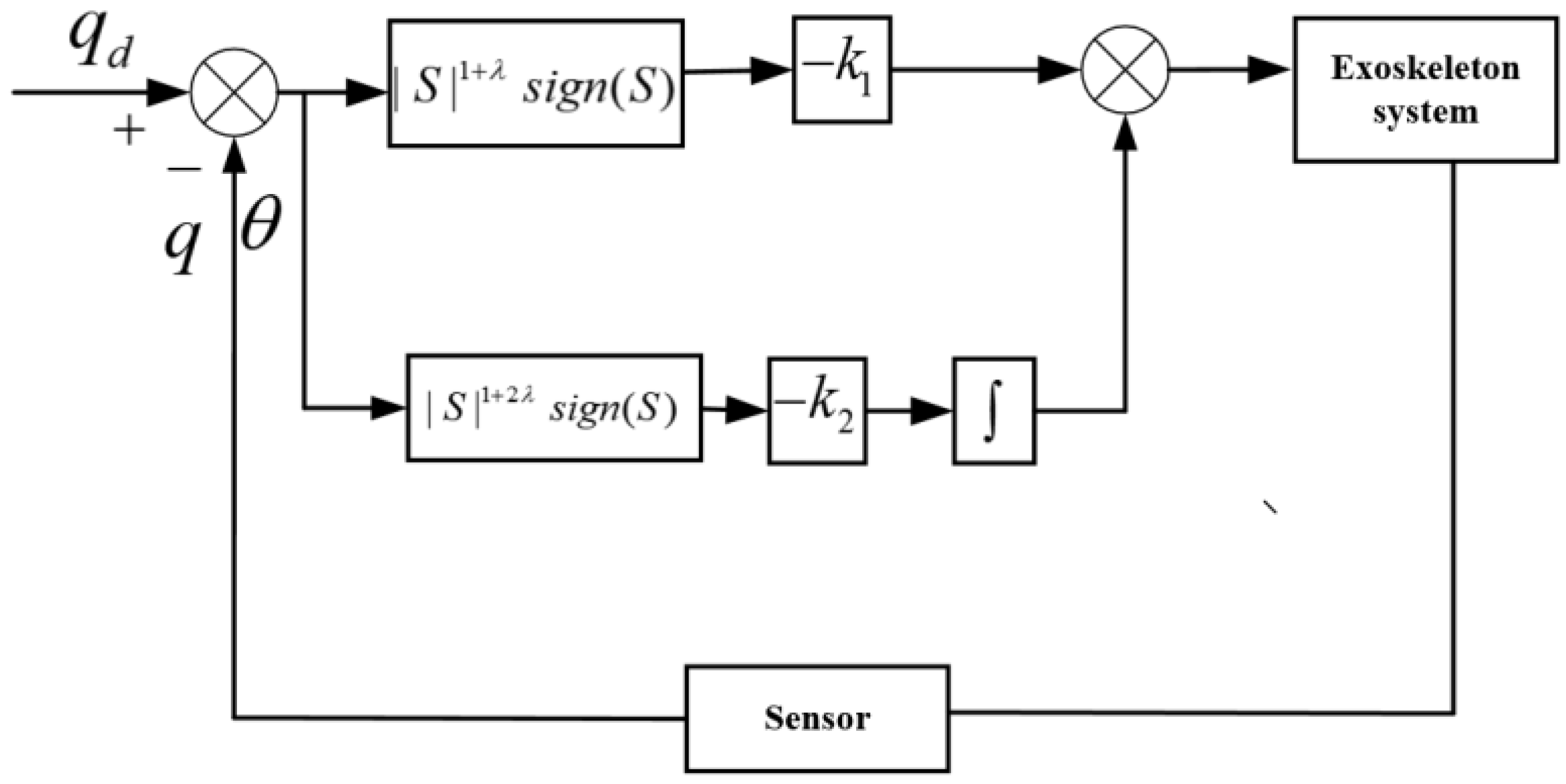
The control structure is shown in
Figure 1. The exoskeleton system feeds back the angle of the joint measurement and the motor side, and then uses ISTSMC to realize the bounded stability of the closed state of the system. The parameter
can be adjusted to achieve the desired effect.
3. Stability Analysis
Theorem 1. This subsection will prove that states and
in the system converge to the following region:
Remark 1. From Theorem 1 we can determine thatis the boundary of the angle error. By selecting appropriate parameters, the angle error can be converged to arbitrarily small, thus ensuring the accuracy of trajectory tracking.
Remark 2. Although STSMC has strong anti-interference ability, the long-term operation of the exoskeleton may be adversely affected due to the switch function under the integral. In addition to the impact of sampling time on the controller, the anti-interference performance of STSMC is not necessarily stronger than ISTSMC in actual use.
Proof of Theorem 1. Substituting (9) into (7) yields:
where
, the above equation can be rewritten as:
Let
, one receives:
For the convenience of calculation:
According to Lemmas 1 and
, we can obtain
According to Lemma 4, we can obtain
where
.
Design the Lyapunov function as follows
where
and
.
Derivative for
, one receives
According to Lemma 3 and (15)
where
. By using (19) and (20), one receives
The same reason can be proven as
where
.
By combining (18), (21) and (22), one gets
In selecting
, make
, one receives
where
.
By employing Assumption 1, it is not difficult to obtain
Definition ,where is a positive constant, and is a sufficiently small constant.
Since
, one receives
According to Definition 1, we can get and are homogeneous of degree pertaining to the dilation weight .
From Lemma 4, one receives
Substituting (27) in (25) yields
In order to ensure that the system can exist at any initial moment
for a time
such that
.
According to Definition 1, we can get and are homogeneous of degree pertaining to the dilation weight .
From Lemma 4, one receives
From (29), it follows that there exists a time
such that
. When
, there exists
Since
, one receives
From the above two equations, it follows that and converge to the infinitesimal range in finite time again. □
4. Experimental Analysis
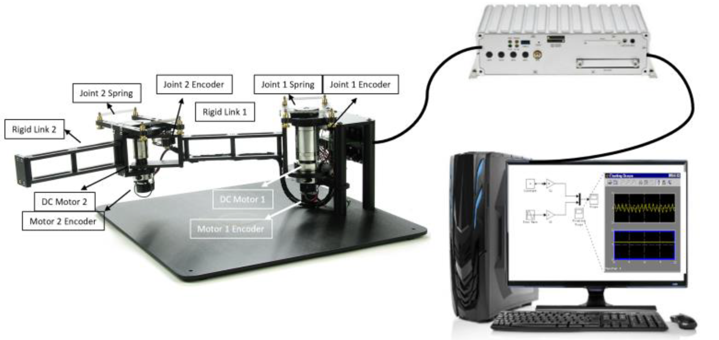
This section uses the two-degree-of-freedom flexible upper limb exoskeleton experimental platform to verify the effectiveness and feasibility of the proposed ISTSMC algorithm. The experimental platform is shown in
Figure 2, including a two-degree-of-freedom upper limb exoskeleton, an industrial computer (to collect information such as angle and torque), and PC_MATLAB/Simulink (to process the collected signals). The main body of the platform consists of two MAXON DC motors, two reducers, and two rigid connecting rods. The first joint is connected to motor 1 through a spring, the end of the joint is motor 2, and the second joint is connected through a spring. Each motor has a quadrature encoder on the bottom and joint side. The springs at both joints are replaceable to adjust the flexibility of the joints. The nominal values of its parameters are listed in
Table 1.
In order to verify the effectiveness of the proposed algorithm, it was compared with a widely used PID controller. Additionally, it is compared with STSMC to verify the ability to reduce chattering. The parameters of the selected controller are in
Table 2In the selection of PID parameters, the response speed of the system will be accelerated with the increase of P, but too large a value of P will cause the system to be unstable; I is used to eliminate static errors, and with a larger integral action comes a slowed response speed of the system. D can reduce the overshoot of the system and speed up the dynamic response of the system. in STSMC and ISTSMC guarantees the boundedness and stability of the steady-state response of the system. The larger is, the faster the convergence speed will be, but if it is too large it will also cause chattering in the system. The larger , the smaller the system overshoot; can reduce the steady-state error of the system. The size of in ISTSMC affects the steady-state of the system error, and anti-interference ability undergoes specific experimental analysis in the fourth section.
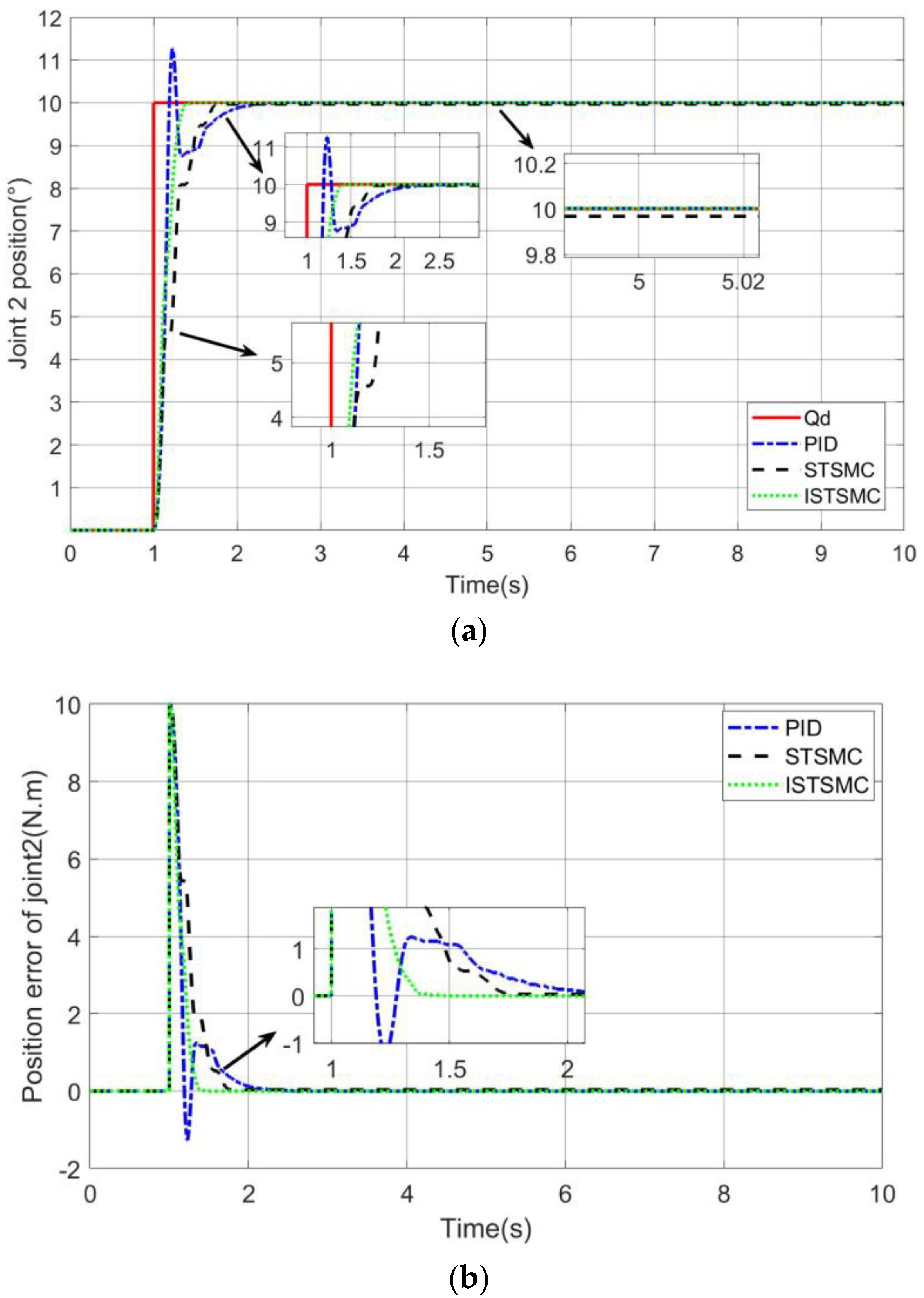
Case 1: The effect of PID, STSMC, and ISTSMC when tracking the step signal.
It can be seen from
Figure 3 that in order to speed up the tracking speed, the PID has 11% overshoot. Although STSMC has no overshoot, the response slows down and only tracks the step signal after 0.7 s. The ISTSMC proposed in this paper can track the upper signal after 0.3 s without overshooting, which is 57% faster than STSMC.
Case 2: The effect of sudden increase of control torque on tracking effect.
In order to verify the anti-disturbance performance of the proposed controller, at 5.9 s, the torque output is suddenly increased by 50%. It can be seen from
Figure 4 that the PID directly loses the ability to stabilize. STSMC gradually converges after being disturbed for 0.7 s, and ISTSMC can overcome the influence of disturbance within 0.1 s, showing excellent anti-disturbance ability.
Case 3: The effect of on the controller in ISTSMC.
In order to verify the influence of
on trajectory tracking, parameter
is set to 40, and parameter
is set to 200. As shown in
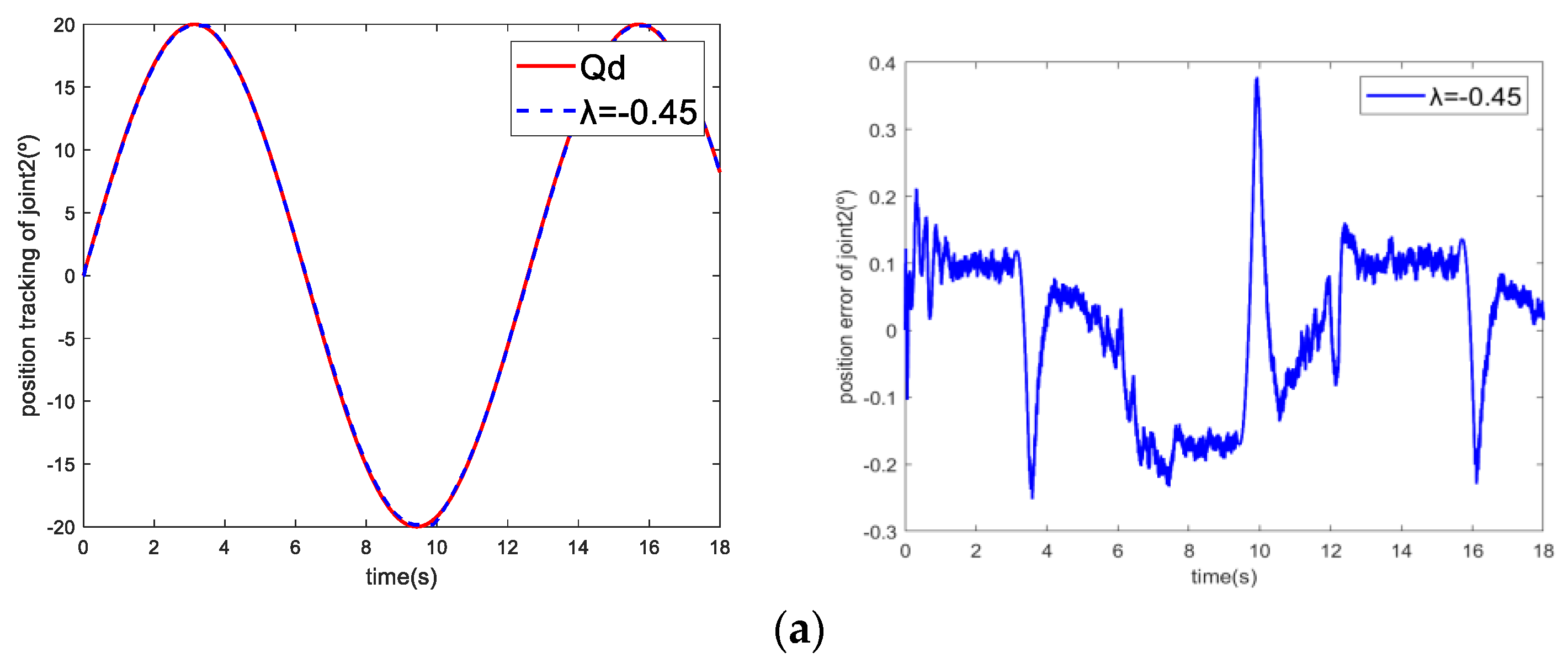
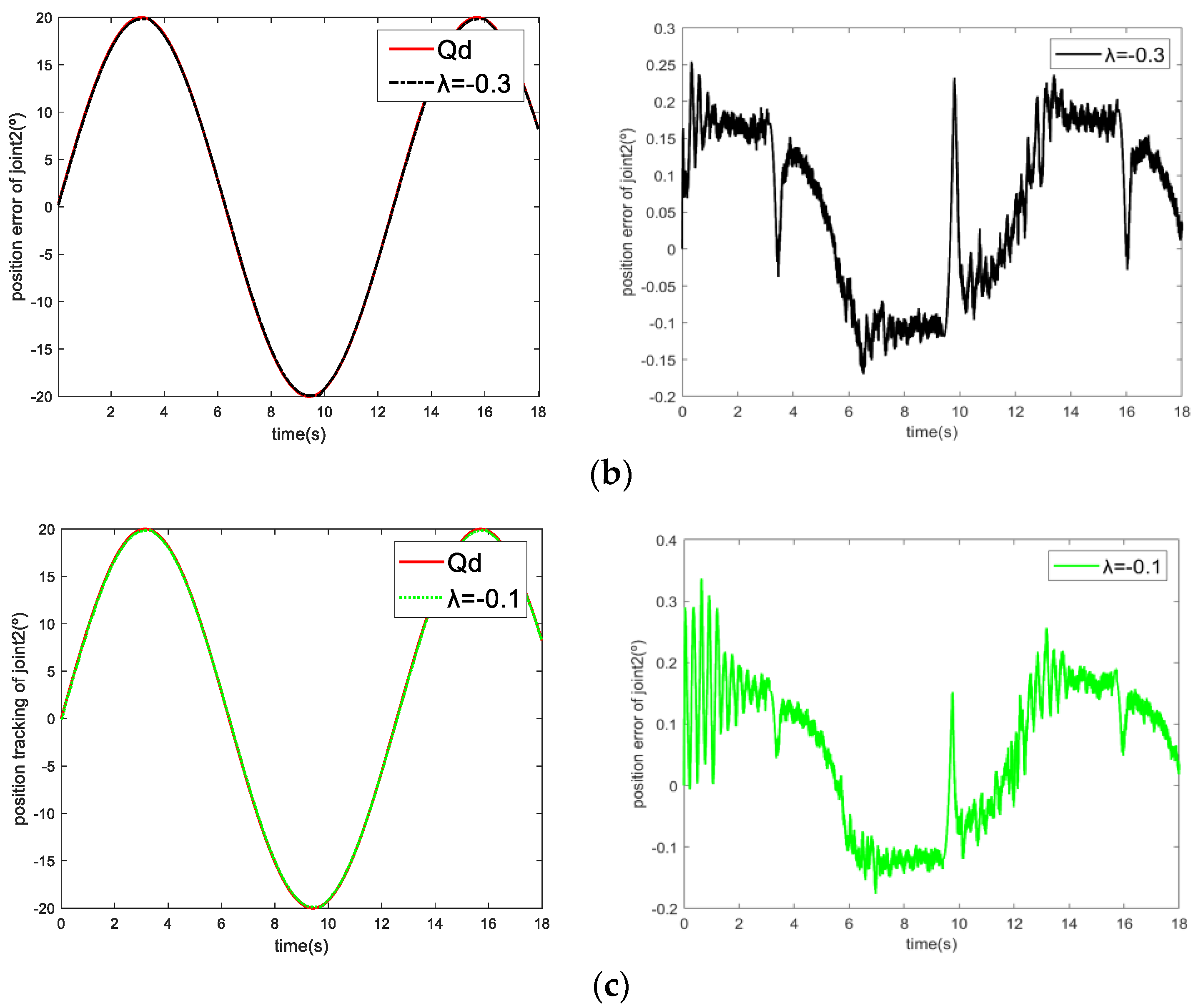
Figure 5, when
,
, and
, increasing the parameter
will increase the chattering of the system, but the tracking error will decrease.
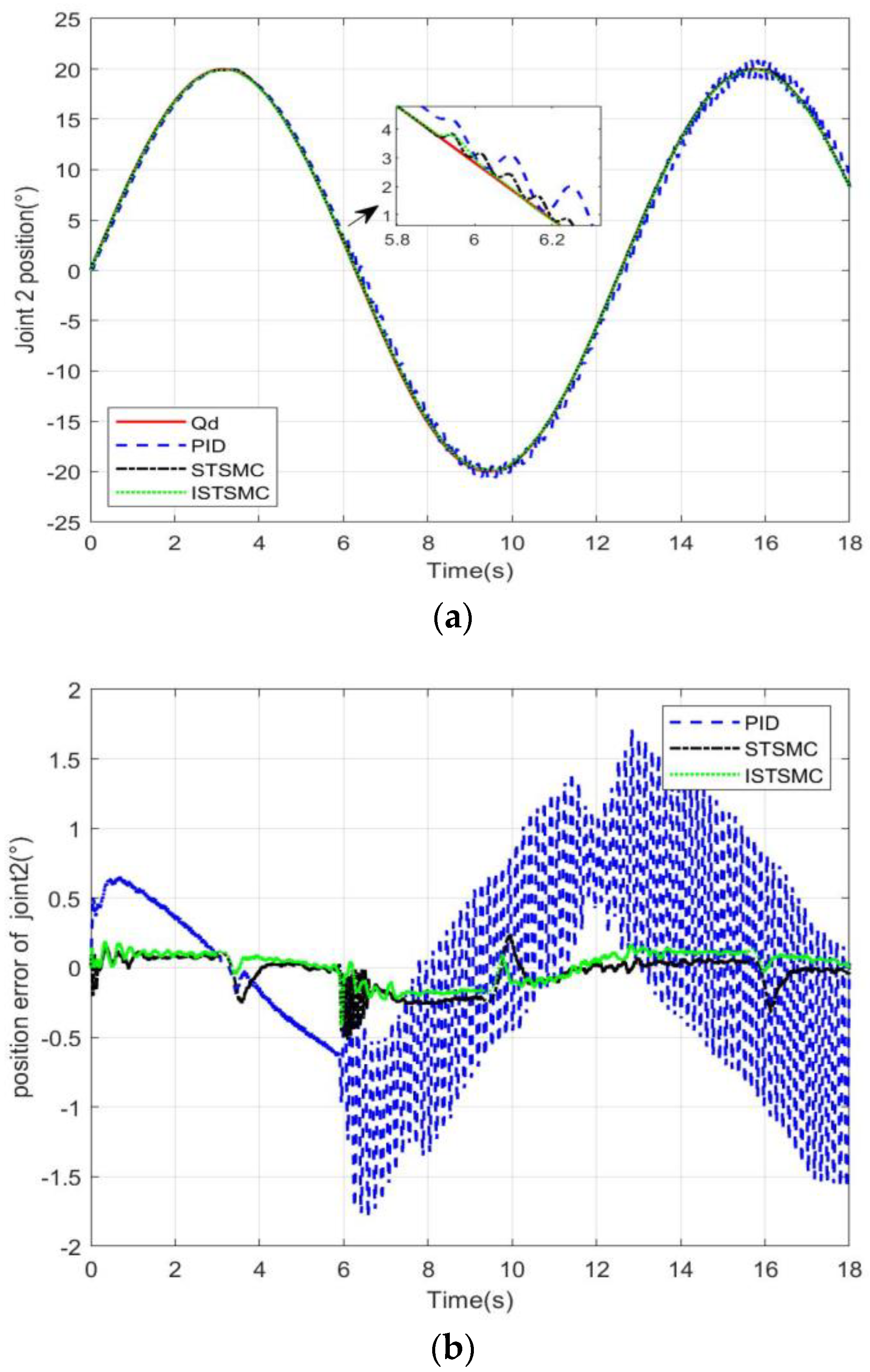
Case 4: Simultaneous tracking of sinusoidal trajectories by dual joints.
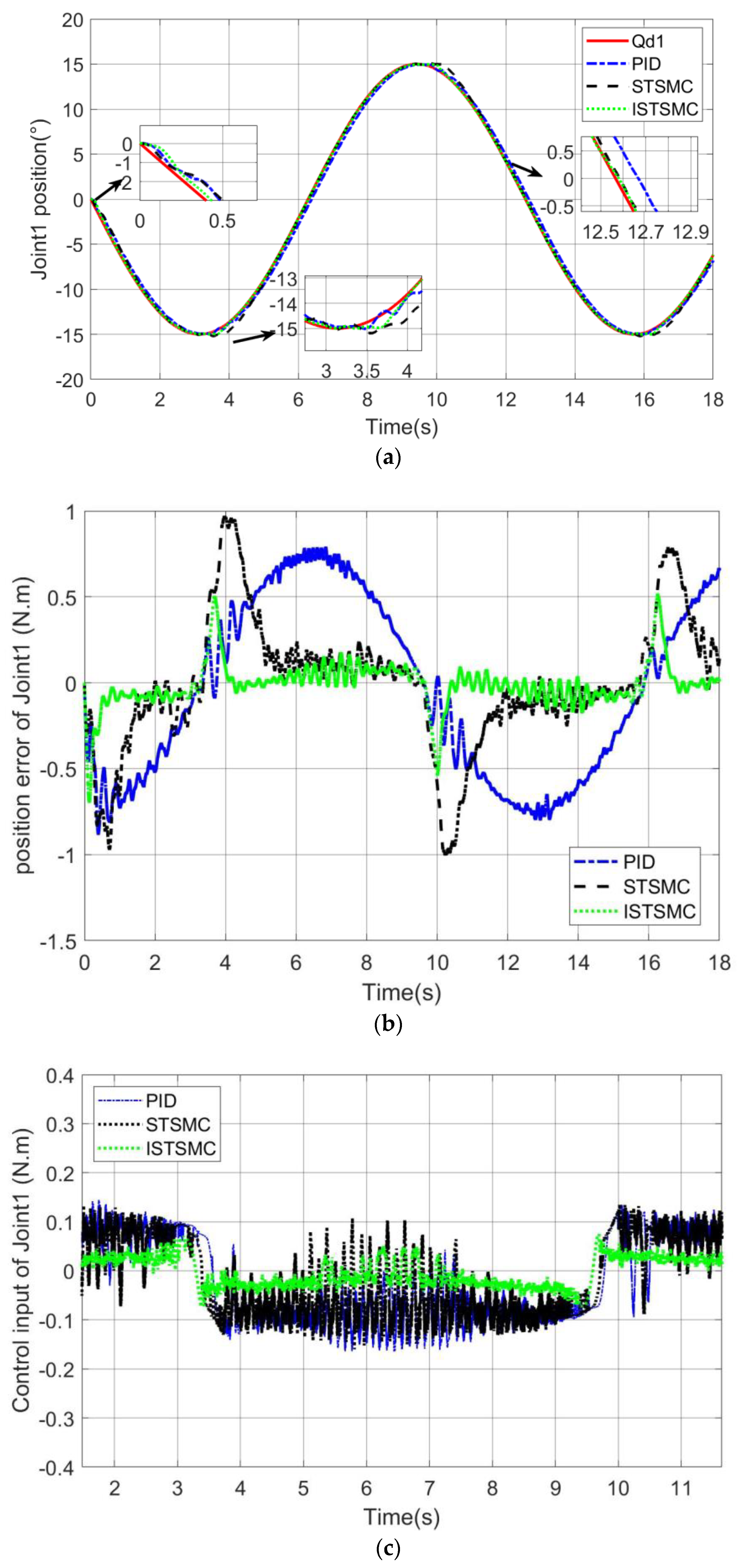
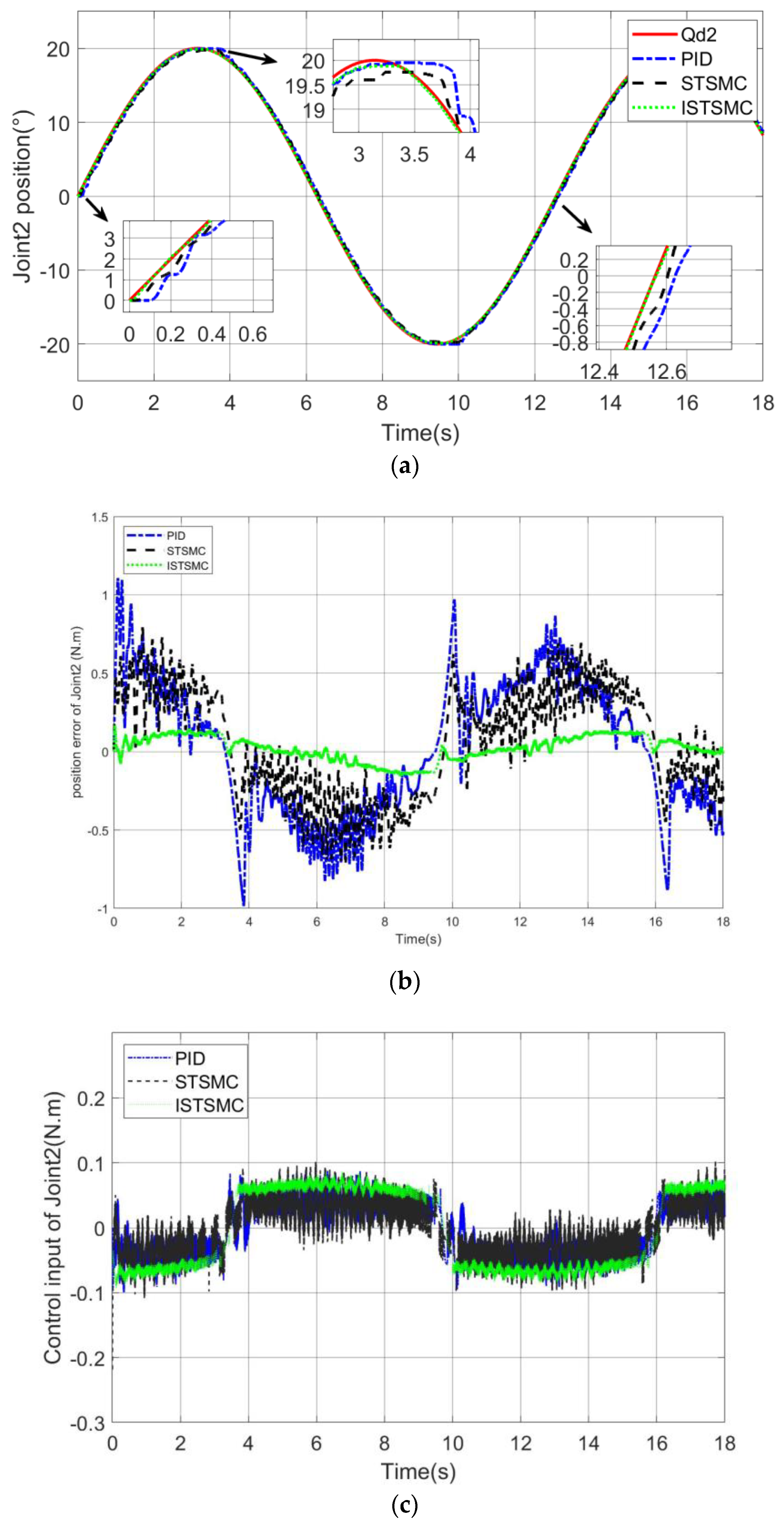
The initial angle of the two joints before the start of the experiment was 0 degrees, the set trajectory of the joint 1 was , and the trajectory of joint 2 is .
From
Figure 6a joint 1 trajectory tracking and
Figure 7a joint 2 trajectory tracking it can be seen that the control responses of STSMC and ISTSMC are faster than PID control and can track the upper trajectory in 0.1 s. The state can see that ISTSMC has a smaller error than PID and STSMC. The trajectory tracking has a "flat top phenomenon", which is caused by the elastic structure of the spring, which causes the the system have a certain hysteresis effect during the commutation process. ISTSMC handles this phenomenon better than PID and STSMC.
From
Figure 6b joint 1 error and
Figure 7b joint 2 error it can be seen that under the ISTSMC algorithm, the steady-state error of joint 1 is about 70% less than that of PID and the commutation error is 40% less than that of STSMC. At 4 s and 10 s, the joint trajectories are reversed. Due to the deformation of the torsion spring, the two joints have the largest error, but they are within the acceptable range. It can be seen from
Figure 6c and
Figure 7c that the control torque of ISTSMC is similar to the other two methods, but the control effect is significantly improved and the vibration is also reduced.
