Abstract
Although exosuits have several advantages compared to exoskeleton type of wearable robots, they have limitations, such as bulkiness and low control performance. This study addresses the design and evaluation of a compact, lightweight, and highly responsive actuator to be used for exosuits, based on the Quasi-Direct Drive (QDD) actuation. The design requirements of the actuator were set based on the actuation system used in the state-of-the-art exosuit from Harvard University (HE) so that it could be an improvement compared to HE. Several design concepts were comparatively evaluated to select the optimal design, and a design for the pulley embedded QDD (PEQDD) actuator was selected. The PEQDD was fabricated using mechanical components selected based on the design constraints or designed through mechanical analysis. Using a dynamometer, the efficiency map of the PEQDD was drawn. The control bandwidth comparison test with the motor originally used for HE showed improved bandwidth from 6.25 Hz to 20 Hz. Preliminary testing was done in walking and running conditions using an exosuit utilizing PEQDD. The test results showed that the actuator performance met all the design requirements.
1. Introduction
To enhance the physical capabilities of human beings, various types of wearable robots have been developed. Until the mid-2010s, wearable robots incorporated rigid frames in their design and were actuated by electromechanical components, such as motors, to exert strong assistive forces to the user [1,2,3]. Robots such as these were categorized as the exoskeleton-type. To manipulate their heavy frames while exerting great assistive forces, the robots require high-powered actuation systems. Because of their rigid frames and bulky actuators, the exoskeletons are bulky and heavy, which makes them uncomfortable for the user to use in everyday life.
To overcome the limitations of exoskeleton-type robots, researchers of Harvard University and others proposed the concept of exosuits [4]. This robot was focused on being lightweight and comfortable for the wearer. The Harvard exosuit (HE) was fabricated with textile materials, which minimized the restriction of natural movements. This also reduced the device weight, resulting in less discomfort from the device’s momentum when moving. By using a Bowden cable to transfer assistive forces, the device had an actuation system that could bend to match the posture of the wearer. Owing to these advantages, research showed that the portable version of HE could reduce the energy cost of walking and running by 9.3% and 4%, respectively [5].
Though the exosuit type of a wearable robot has several merits over the exoskeleton type, it still has limitations, especially in the aspects of size and control performance. Considering the HE, which is said to be the current state-of-the-art exosuit, the design of the device is still heavy and bulky because the actuation system was not custom-made for the robot. Two commercial motors in the shape of a long cylinder with a pulley in the shape of a flat disk for driving the Bowden cable were used for the actuation system [5]. Because the motor and pulley were designed to be coaxial, the resulting actuation system was quite bulky, with the actuation system extruding up to 7 cm from the back of the wearer, as illustrated in Figure 1.
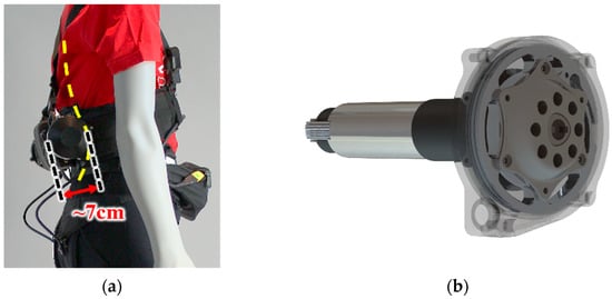
Figure 1.
(a) Sideview of the Harvard exosuit, which extrudes approximately 7 cm [5]. (b) Actuation system used for the exosuit.
The latest research on exosuits still share this limitation. Kim et al. presented a mobile exosuit for hip flexion assistance that could achieve a metabolic reduction of 7.2% during walking when worn, compared to walking without the suit [6]. In another research, Yang et al. designed an exosuit for hip abduction that could reduce the knee adduction moment during walking [7]. Although these cable-driven devices required lower peak force, both of the devices had the limitation of protrusion from the body.
Because of this obtrusive device design, the use of an assistive device is evident while wearing the exosuit, which acts as an obstacle for the device to be used for daily life [8]. Moreover, soft wearable robots tend to have lower tracking performance compared to rigid exoskeletons [9]. The soft characteristics of the exosuit induce large deformation of the suit when a force is applied, which leads to a substantial response delay during actuation. Actuators with high control frequencies should be used to lessen the overall delay, by reducing the delay from actuation systems.
Currently, Quasi-Direct Drive (QDD) actuators composed of high torque density motors and low gear ratio transmission are gaining attention as the new solution to design lightweight, compact mobile robots with high control frequencies [10,11,12,13,14]. Using low gear ratio transmission, the QDD actuators have low reflected inertia, which makes them highly responsive and backdrivable. Moreover, the shape of the QDD actuators has an advantage because of their cylindrical shape with low height and wide radius, and are referred to as “pancake actuators”.
Owing to these characteristics, the actuators have been actively used in various types of robots. For example, the MIT Cheetah robot used QDD actuators to utilize their high torque density for impact mitigation and high-bandwidth physical interaction [12]. Recently, several exoskeletons that utilize QDD exhibited promising results [13,14]. For example, the portable hip exoskeleton based on QDD actuation proposed by S. Yu et al. had high nominal torque and high control bandwidth while being highly-backdrivable and having a light weight of 3.4 kg [13].
To make the actuation system of the exosuit highly responsive, while also making them lightweight and compact, we developed a new cable-driven actuation unit based on QDD. To design the customized actuator for the exosuit, we first set the design requirements of the new actuator, based on the specifications of the HE. Next, the optimal design of the cable-driven actuator was selected by evaluating and comparing several design concepts. A lightweight and compact cable-driven actuator was fabricated, using parts that were selected based on the design constraints or designed through mechanical analysis.
Using a dynamometer, the characteristics of the actuator were analyzed. Furthermore, the control bandwidth of the actuator was measured, and compared to that of the original motor used in the HE, which showed increased performance. Lastly, we conducted preliminary tests of walking and running with an exosuit that utilized the actuator proposed in this study to evaluate the performance of the actuator under real usage.
In this study, a new actuator based on quasi-direct drive actuation, designed specifically for wire-driven exosuits is proposed. The goal of the study is to design an actuator that enables wire-driven exosuits to overcome the former limitations of being heavy and bulky, while matching the required specifications. Using a QDD motor-based pulley embedded design, the actuator not only matched the design requirements, but also showed increased control performances. Design steps and strategies used for designing the actuator, and verification methods of the fabricated actuator are described in the following chapters. This new actuator for wire-driven exosuits will result in lighter, highly responsive exosuits while having low extrusion from the body (see Supplementary Materials).
2. Materials and Methods
In this chapter, the design process for the new actuator is described. First, the design requirements for the actuator are chosen. Secondly, the design variables that can be altered in the concept design are defined, and feasible design concepts are suggested by choosing different combinations from these design variables. The design concepts are evaluated, and the concept that best matches the goals and requirements of the actuator is selected. Based on the selected design concept, detailed designs are made, such as selection of the motor, reduction stage, and other mechanical component design. These steps for the design process are shown in Figure 2.
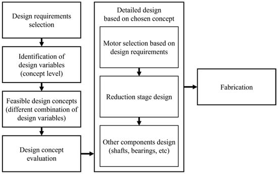
Figure 2.
Schematic for the design process of the actuator.
2.1. Design Requirements
Among various wearable devices that utilize cable-driven actuation, we chose the actuation system with the highest required output, which was the actuation system of HE, as the reference for the actuator performance in this research. This was because HE targeted hip extension for assistance and required the most assistance force compared to the devices mentioned above [6,7,15]. Thus, based on the specifications of HE, design requirements for the new actuator were selected [5]. Selected parameters were output torque and speed, along with the weight and volume of the actuator.
The torque requirement for the actuator was set based on the maximum assistive force of HE, which is designed to exert forces up to 300 N on the user’s body [15]. A pulley of 40 mm radius was used in the HE, which needs at least 12 Nm torque ideally at the actuator to generate 300 N force on the cable. Cable driven systems used in HE use Bowden cables placed inside a stationary cable sheath, and pulling the cable slides the cable inside the sheath. Because of the energy loss from friction between the sheath and cable, the efficiency of the system decreases. Hofmann et al. found the efficiency of the cable-sheath system to be in the form of Equation (1), determined by the bending angle of the cable sheath σ [16].
Based on our previous experiences, the bending angle of the sheath hardly exceeds 30°. Therefore, we assumed the efficiency of the cable, , to be approximately 90%, based on Equation (1). Considering a pulley of 40 mm radius and efficiency of 90% at the cable, the torque requirement at the pulley was set as 13.3 Nm, to match the force requirement.
The speed requirement for the actuator was set based on the specifications of the motor originally used for the HE. The exosuit uses a 200 W BLDC motor (EC-4pole 30, Maxon, Sachseln, Switzerland) with a gear reduction of 51:1 (Planetary Gearhead GP 32 HP 326664, Maxon), which has a nominal speed of 313 rpm after reduction. The rotation speed at the pulley of the new actuator was set to be at least this speed so that the new actuator can have an operating range equal to or wider than the original motor.
Because the new actuator acts as a whole actuation system, the weight and volume requirements of the actuator were set compared to the actuation system of the HE (Figure 1b). The actuation system for one side of the HE weighs 753 g and has a volume of 270 cm3. To make the system lighter and more compact, the target weight and volume of the actuator were set to 85% of the value of the original actuation system, which is 640 g and 230 cm3, respectively. Since space concealed inside the casing cannot be used, the volume was measured including any concealed spaces in the system.
Another factor that is crucial for designing the actuator is the shape of the actuator. Even if the volume of the new actuator is less compared to the original system of the HE, having the same level of extrusion would be pointless. When designing a new form factor for the exosuit that uses the new actuator, we planned to place the actuator with the flat side of the cylinder touching the back of the wearer. The shape of the new actuator was chosen to be a flat and wide cylinder, to maximize the design advantages from using the QDD actuation. This way, the height of the cylinder was to be the dominant cause of extrusion. Considering that the HE extrudes approximately 7 cm from the body, we aimed to design the new actuator to be less than 3.5 cm in height, which is a reduction of 50% compared to the original height. The design requirements set for each parameter are presented in Table 1.

Table 1.
Design Requirements for the Actuator.
2.2. Comparison of Design Concepts
To design the new actuator for exosuits that maximizes the advantages of the QDD type actuators, several design concepts of cable-driven actuators based on QDD were evaluated. The design concepts were made by varying the types and positions of the three crucial components; base motor, reduction stage, and pulley. Only the designs that could potentially meet the requirements while keeping the actuator in the shape of a flat cylinder were considered. Therefore, the reduction stage was considered in the form of a single-stage planetary gear set. After exploring the possible combinations of designs for each component, three design concepts were selected and comparatively evaluated, as presented in Figure 3, to select the optimal design for the actuator.
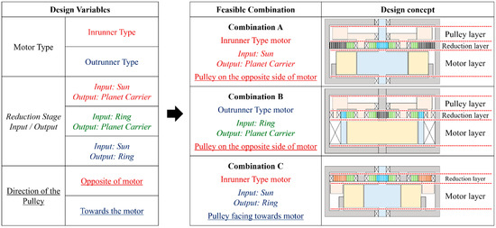
Figure 3.
Design variables and combinations selected for comparison. The design concepts are shown with a cross-sectional view in which gray color stands for the stationary parts. Similarly, the orange color is for the stator, blue is for the rotor and the input of the reduction stage, red is for the output of the reduction stage with the pulley, and green is for the planetary gears. Sun and ring gears are the most inner and outer gears, respectively, and the planet carrier is the middle gear between them. Gears are expressed with vertical stripes, and bearings are marked with an X.
For a fair comparison among the design concepts, we set the pulley diameter and ring gear size to be the same, and the power ratings of the motor to be similar for all concepts. Afterward, the motor, gear set, and the position of each component were optimally determined for each concept. The diameter of the pulley was fixed as 80 mm. We considered only motors that have smaller diameters than this pulley diameter. The thickness of the motors was set using commercial motors with similar power ratings as reference. Only the planetary gear sets that could be designed inside the pulley diameter were considered, in order to keep the diameter of the actuator minimal. The expected weight, height, and gear reduction ratio of each design were used as the parameters for evaluation.
For design A, the sun gear acts as the input, and the planet carrier acts as the output of the reduction stage. As the sun gear is the input gear, an inrunner type of motor was selected. This design has three layers within the casing namely, the motor, reduction stage, and the pulley. To be connected to the pulley, the planet carrier must extend outwards of the reduction layer, in the direction of the pulley. The pulley must take up one additional layer of the structure by itself because the planet carrier cannot extend in the direction of the motor layer. This design does not have much advantage in height because of the pulley layer. Moreover, the structure will be relatively heavy because of the weight of the planet carrier.
Design B uses the ring gear as the input and the planet carrier as the output. Since the ring gear is used as the input, an outrunner type of motor was selected. The design consists of three layers, the same as Design A, and this design also needs a separate layer for the pulley for the same reason. Since the layers are separated, this design also does not have an advantage in height. The planet carrier and the bearing for the ring gear will add weight, so the design will be heavier than Design A.
Lastly, Design C uses the sun gear as the input, and ring gear as the output. With the sun gear being the input, an inrunner type of motor is used. This design has two layers, the motor layer and the reduction layer, because of the pulley being overlapped with the motor layer. The pulley is attached to the ring gear, and the motor is placed inside the ring-shaped pulley. This placement greatly decreases the height of the actuator owing to the eliminated height of the pulley layer, present in the other designs. The planet carrier is stationary and is therefore reduced to a form of shafts on the casing. The reduced form of the planet carrier makes the design lighter than other designs.
Since we considered designs that use only a single planetary gear set as the reduction stage, the torque requirement also becomes the dominant factor in motor selection. Thus, designs that enable the use of higher gear ratios with a single planetary gear stage are desirable. The maximum feasible gear ratio of the three design concepts can be compared using Equations (2)–(4). The equations denote the gear reduction ratio for each combination of input and output in the reduction stage.
The gear reduction ratio is expressed as r, with the input and output of the reduction stage notation in subscript. S, P, and R stand for sun gear, planet carrier, and ring gear, respectively, with the input as the denominator, and the output as the numerator. , , and are the number of teeth in the sun, planet, and ring gear, respectively. Comparing the denominator and numerator on the right side of the three equations yields that the maximum feasible gear ratio of design A is the highest for any value of and , followed by designs C and B.
Overall, design C has the best attributes in actuator height and weight and is the second-best in reduction ratio. It is expected to have a lower height than designs A and B. Furthermore, the gear ratio of design C increases close to the gear ratio of design A, as decreases. From these comparisons, design C was selected as the optimal design for the new actuator.
2.3. QDD with Embedded Pulley
To design the actuator, components such as the motor and the encoder were selected after searching for optimal commercial products that could meet the design requirements. Other components, such as gears and shafts, were custom designed so that they can withstand the loading conditions while satisfying the design requirements. The components of the actuator were designed in order of importance.
2.3.1. Motor Selection Based on Design Requirements
Design C selected in Section 3 uses a frameless inrunner type motor. Based on the design requirements of the actuator, the requirements for weight, size, and performance of the base motor were set.
We did a preliminary draft of the actual design for the actuator to check the estimated weight of the components. The total weight of the components other than the motor was assumed to be approximately 440 g. To meet the weight requirement for the whole actuator, which is 640 g, the motor needs to weigh lesser than 200 g.
For the motor to be placed in the middle of the pulley, the outer diameter of the motor is determined by the size of the pulley. For the detailed design, the pulley must have a socket to embed the end of the Bowden cable. For this, the inner diameter of the pulley should be 65 mm, and the outer diameter of the motor should not exceed this value.
To keep the actuator height from increasing, we chose an incremental magnetic encoder unit (RLB series, RLS, Žeje pri Komendi, Slovenia) with a magnetic ring (MR series, RLS), which can be placed inside the hollow rotor of the motor. Considering the shape of the encoder and the magnetic ring, the inner diameter of the rotor should be over 24 mm to place the encoder.
The design requirement of the actuator height is 35 mm. Considering the height of the reduction stage layer and the height increase from the casing, the height of the motor should not exceed 27 mm. Furthermore, the height of the rotor should be over 15 mm to place the encoder inside.
As we are using a single stage for reduction, it is difficult to make the reduction ratio more than 10:1 in the detail design. Therefore, the torque requirement at the pulley was 13.3 Nm, so the peak torque of the motor should be greater than 1.33 Nm. Furthermore, the speed of the motor should be greater than 3130 RPM to meet the speed requirement of 313 RPM. Based on the rated torque of the actuation system used in the HE, which is 4.76 Nm, the required rated torque was set as 0.476 Nm. The overall design requirements for the motor are presented in Table 2.
Table 2.
Design Requirements for the Motor.
Motors from four manufacturers (T-MOTOR, Jiangxi, China; Allied Motion, Amherst, NY, USA; Celera MOTION, Bedford, MA, USA; WITTENSTEIN, Igersheim, Germany) were compared based on their specifications from the manufacturer catalogs [17,18,19,20]. The specifications of each motor and whether they meet the requirements are presented in Table 3. Among all the motors that were compared, RI60 KV120 from T-MOTOR was chosen to be used as the base motor.
Table 3.
List of the optimally selected commercially available frameless motor.
2.3.2. Design of the Planetary Gear Set
A planetary gear set from the selected design concepts that use sun gear as the input and ring gear as the output was designed to match the desired torque requirement of the actuator. The selected motor has a peak torque of 1.63 Nm, which needs gear reduction over 8.16:1 to meet the torque requirement of the actuator; 13.3 Nm.
The gear reduction ratio of planetary gears can be calculated from Equation (4), where the minus sign stands for change in direction between the input and output. The fundamental equations for the number of teeth in each gear of planetary gear set are shown in Equations (5)–(7):
where is the number of the planet gears [21].
From Equation (4), should be minimized to maximize the reduction ratio. We set as 14; the minimum number of teeth that can prevent undercut with a pressure angle of 20°. To meet the gear reduction requirement, should be greater than 114. Furthermore, should be lesser than 130, to have a diameter lesser than the inner diameter of the pulley; 65 mm, with a gear module of 0.5 for stable driving. We selected the value of that satisfies all the constraints while having a robust structure, which is 118. Using the sets and , Equations (6) and (7) can only be satisfied when is 2 or 3. To minimize the loading conditions of the planetary shaft and gears, was set as 3.
The designed planetary gear set had a reduction ratio of 8.428:1. Rated torque, peak torque, and speed calculated with the gear ratio were 4.8 Nm, 13.74 Nm, and 664 RPM, respectively, which met the design constraints. The specific design process for each gear was performed using CAD (Inventor 2022, Autodesk, San Francisco, CA, USA). We designed the gear set to prevent mechanical failures under the material property, while minimizing the width of the gear to minimize the height of the actuator, so we used gears with 4 mm width. Table 4 presents the specifications of the reduction stage.
Table 4.
Specifications for the Planetary Gear Set.
2.3.3. Other Mechanical Components
The shafts of the sun and planet gears were analyzed from the strength and stiffness point of view to prevent mechanical failure. Since the sun gear and the shaft were designed as a single part, SCM415 was used for the material of the sun gear shaft like the sun gear. Planetary gear shafts were designed to be directly combined with the casing, so Al7075-T6 was used to reduce the overall weight of the actuator.
When calculating the minimum permissible shaft diameters from the material strength aspect, a safety factor of 3 was used considering extreme loading conditions. The sun gear shaft was analyzed with the effect of the notch for key insertion, and characteristics of soft material (Al7075-T6) were considered for the planet gear shafts. Required shaft diameters were calculated using Equations (8) and (9).
In the above equations, and are the tensile and shear strength of the material, is the bending stress, is the torque, and and are the fatigue stress-concentration factors for bending and torsion [22,23]. For the sun gear shaft, a minimum required diameter of 4.7 mm was obtained from Equation (9), by using a value of 4.43. Since the planet gear shaft does not have any notches, a value of 1 was used to obtain the required planet gear shaft diameter of 5.27 mm from Equation (9). Consequently, a diameter of 5 mm and 6 mm were used for the sun gear shaft and planet gear shafts, respectively, that could satisfy the minimum permissible shaft diameters.
Bearing selection has the most influence on the driving stability of the actuator. Noises and vibrations during actuation can be minimized when the clearance between the inner diameter of the bearings and the outer diameter of the shaft is minimized. Since we are designing an actuator for exosuits that comes in direct contact with the users, reducing the noise and vibration from the actuator is crucial. Therefore, we selected bearings of the highest grade with driving conditions of each rotational component put into consideration.
The sun gear shaft, which is directly connected to the rotor, has a constant gap between the rotor and stator. Therefore, a bearing of grade ABEC5 (7804K129, McMaster-Carr, Elmhurst, IL, USA) was used at each end of the sun gear shaft. For the planetary gears, bearings of grade ABEC3 (57155K587, McMaster-Carr) were used, considering the length of the shaft is shorter than the sun gear shaft, and the speed of the planet gears being slower than the sun gear. A bearing of grade ABEC0 (6813ZZ, NSK, Tokyo, Japan) was used for the ring gear and pulley, which had the largest support area compared to other components.
2.3.4. Prototype Manufacturing
Using the selected components, a Pulley Embedded QDD actuator (PEQDD) was fabricated, as illustrated in Figure 4. The actuator had a diameter, thickness, volume, and mass of 93 mm, 31.5 mm, 203 cm3, and 590 g, respectively.
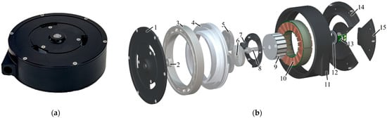
Figure 4.
PEQDD prototype (a) Manufactured and (b) Exploded view of PEQDD. 1. Front cover, 2. Sun gear bearing, 3. Ring gear bearing, 4. Pulley integrated ring gear, 5. Planet gear, 6. Planet gear bearing, 7. Planet gear carrier, 8. Sun gear shaft, 9. Rotor, 10. Stator, 11. Middle cover, 12. Encoder–Magnetic ring, 13. Encoder–Reading head, 14. Bottom cover, 15. Removable bottom cover.
The pulley and the ring gear were merged into a single part, and the bearing that holds this part was placed on the outer side of the planetary gear stage. To efficiently change the Bowden cable without dismantling the entire actuator, a part of the bottom casing was designed to be easily detachable. To secure the planet gears and to reduce any possible deformation of the planet gear shaft under loading, a part that can hold the shafts was added. Nitriding was applied for the sun gear and the planet gears to increase the surface hardness of the gears, and the casing was anodized to prevent possible rusting.
3. Results (Performance Evaluation of the PEQDD)
In the process of developing actuators, performance testing in different conditions is needed. Without this information, the actuator is unreliable for designing a product that needs to meet specific requirements in various conditions. Moreover, not knowing the efficiency of an actuator can lead to inefficient usage. We evaluated the performance and the characteristics of the PEQDD actuator through experiments. Furthermore, an exosuit with PEQDD actuation was fabricated to preliminary compare the actuator with the actuation system of HE.
3.1. Performance Evaluation: Steady–State Condition
Representative parameters for the steady-state performance are torque, speed, and energy efficiency. Efficiency is one of the important characteristics of the actuator and is defined as the ratio between the mechanical energy output and electrical energy input. Testing for efficiency under different speed and loading conditions can show the robustness of the actuator. The steady-state performance of the PEQDD was measured with a dynamometer, using the setup illustrated in Figure 5.
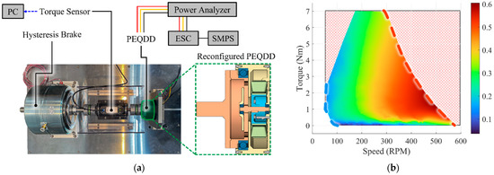
Figure 5.
Testbed setup and efficiency map of PEQDD (a) Dynamometer testbed setup to measure the steady-state performance of PEQDD. (b) Energy efficiency map of PEQDD at steady-state condition. The area marked red is out of operation range.
The dynamometer used for testing was composed of a rotary torque sensor (M425, datum electronics, Isle of Wight, UK) to measure the torque and rotational speed, with a hysteresis brake (AHB-24, Valid Magnetics, Hong Kong) that could exert steady loading on the actuator. We used a switching mode power supply (SE-1500-48, MEANWELL, New Taipei City, Taiwan) to power the actuator, with an electronic speed controller (ESC; FLAME 100A 14S, T-MOTOR). To measure the input electric power provided to the actuator, a power analyzer (WT-1804e, Yokogawa Electric, Tokyo, Japan) was placed between the ESC and the actuator.
The design of the actuator with the pulley facing downwards toward the direction of the motor was not adequate for connecting to the dynamometer, so the configuration of the actuator was modified as presented in Figure 5a. Without changing the components of gear transmission, the direction of the pulley was reversed so that the pulley was placed facing upwards, on the topmost layer of the actuator. The upper casing that held the planet gears in place was repositioned below the reduction stage, due to the pulley facing upwards. An additional part was used to connect the pulley to the dynamometer.
For the test conditions, the input voltage of the motor and the load acting on the actuator from the brake were varied. The input voltage was given from 18 V to 48 V, with an interval of 3 V between the conditions. For each voltage condition, we used the hysteresis brake to apply torque to the pulley while keeping the voltage steady. Starting from the no-load condition, we increased the torque to the point of a stall in each of the voltage conditions, or to the point where the motor temperature exceeded 150 °C, where temperatures over this point can cause permanent damage to the motor. Load conditions of this point and above were not tested and are seen as conditions that are out of steady-state operation range. The amount of torque from the hysteresis brake was controlled with the input current of the brake, which was given with an interval of 25 mA for each condition. For each condition, the temperature of the motor was cooled below 25 °C before starting the tests.
Efficiency for each condition was calculated from Equations (10)–(12), with data acquired for 5 s after applying the load.
and indicates the input electrical power and output mechanical power. was calculated from input electrical voltage and current, and , that were measured from the power analyzer. Applied torque and actuator velocity data, and , acquired from the torque sensor were used to calculate .
Figure 5b presents the efficiency map of the actuator, drawn from the test points. We used MATLAB (R2021b, MathWorks, Natick, MA, USA) to analyze the data and used a lowpass filter with a cutoff frequency of 1 Hz on the data acquired by the power analyzer and torque sensor. An additional median filter with a window size of 100 was applied to the calculated efficiency to better show the steady state results by evening out any leftover noise. The map was drawn by the natural neighbor interpolation method, using the normalized data from all test conditions.
In Figure 5b, the points marked with the dashed blue and red lines are data from the conditions with an input voltage of 18 V and 48 V, respectively. The test results indicate that the efficiency of the PEQDD actuator is in the range of 0–0.605, and the efficiency increases as the input voltage increases. For a certain actuation speed, efficiency increased as the load increased from no-load condition to a 1.5 Nm, then gradually decreased with increased load. Maximum efficiency was achieved around the loading condition of 1.5 Nm, regardless of the input voltage. The maximum speed recorded was 580 RPM at 48 V. Through this analysis of steady-state performance, we confirmed that the design of PEQDD has no fatal defects in power transmission.
3.2. Performance Evaluation: Control Bandwidth
The controller for the exosuit that has been developed within our lab utilized the force control based on the admittance control, which uses position control as a low-level controller, i.e., we can expect improvement in the admittance control and force control, based on the improvement in control bandwidth of the position control.
We compared the control bandwidth of the PEQDD and the actuator used in the HE, with the position closed-loop condition using a tunning program (Elmo Application Studio II, Elmo Motion Control Ltd., Petah Tikva, Israel) and motor controller (Gold Solo Twitter R50/100, Elmo Motion Control Ltd., Petah Tikva, Israel). By using the automated identification tool, which was built-in to the tunning program, we applied 100% continuous current to both actuators in no-load conditions. Motion to rotate the pulley for 1 rev was generated, using frequencies between 0.1 and 100 Hz. As shown in Figure 6, the cut-off frequency of the PEQDD was 20 Hz, whereas the Maxon was 6.25 Hz. Through the increase of the cut-off frequency, we can expect an increase in the controllability of the force controller. This increase in control performance will better relieve the delay of force transmission between the actuation system and the human body.
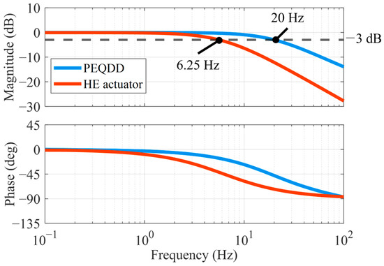
Figure 6.
Result of the control bandwidth test between the PEQDD and Maxon motor.
3.3. Preliminary Test: Implementation to Exosuit
We conducted preliminary tests to evaluate the performance of the PEQDD, integrated into an exosuit in actual driving conditions, such as walking and running. For the tests, we developed a new version of the hip exosuit that utilized PEQDD, as shown in Figure 7b.
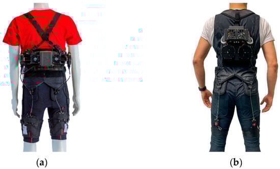
Figure 7.
Comparison of the actuation pack of the hip-extension exosuit. (a) Exosuit designed by Harvard University [5]. (b) Renewed Exosuit, based on the proposed PEQDD actuators.
To verify the performance of the PEQDD, preliminary tests were conducted with a single healthy male subject (age: 27 yrs.; height: 1.76 m; weight: 69.4 kg). The subject walked and ran for 2 min at 1.4 and 2.1 m/s, respectively. Since the test was preliminary, the force profile range was set between 200 to 250 N, lower than the maximum performance of PEQDD, for the safety of the subject and actuation system. Force data were sampled at 1 kHz with loadcell (LSB205, Futek, Irvine, CA, USA) and real-time controller (CompactRio9040, National Instruments, Austin, TX, USA) and were filtered using a low-pass filter with 20 Hz cut-off frequency.
Figure 8a,b present data of 10 strides within the measured data of 2 min during walking and running, respectively. As shown in Figure 8, the peak force was mostly stable within the target range. The peak force on the left and right leg during walking was 232 ± 3.47 and 235 ± 9.28 N (mean ± Standard Error of the Mean: SEM), respectively, and peak force on the left and right leg during the running was 215 ± 3.90 and 210 ± 2.98 N (mean ± SEM), respectively. For some of the strides during walking, an intermittent peak force of over 300 N was delivered. From this, we can infer indirectly that the PEQDD can potentially deliver forces over 300 N, which was set as the design requirement. The maximum speed of the pulley rotation during walking and running conditions were 301 RPM and 341 RPM, respectively.
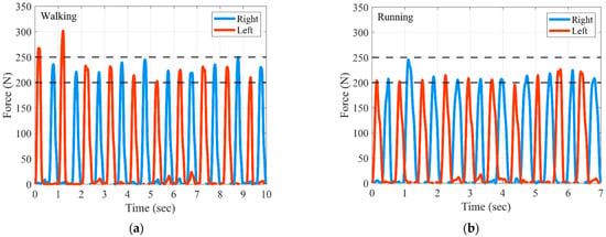
Figure 8.
Preliminary test result from the PEQDD implemented to a hip extension exosuit. (a) Force profile: walking condition. (b) Force profile: running condition.
4. Conclusions
In this study, we proposed a new actuator based on quasi-direct drive actuation that has an embedded pulley named PEQDD. This actuator is compact, lightweight, and has a high control bandwidth, compared to the cable-driven actuation system of the state-of-the-art HE. To select the optimal design for the actuator to be used in an exosuit, various design concepts for the actuator were evaluated. The fabricated PEQDD had a diameter, thickness, volume, and mass of 93 mm, 31.5 mm, 203 cm3, and 590 g, respectively.
The performance of the PEQDD was evaluated through various experiments. Using a dynamometer, we evaluated the efficiency of the PEQDD in a steady-state condition. The maximum efficiency of the PEQDD was 0.605. We evaluated the control bandwidth of the actuator in the position closed-loop condition. The cut-off frequency of the PEQDD was 20 Hz, while that of the Maxon motor, utilized in the Harvard exosuit, was 6.25 Hz.
Preliminary tests were conducted by wearing a hip extension exosuit that utilized the PEQDD, and results indicated that the PEQDD had satisfied all the design requirements.
Although the evaluation results for the actuator indicated adequate performance, certain aspects require further examination. First, the control bandwidth has to be evaluated with a force controller, which has been utilized in the exosuit. Experiments under various conditions will be conducted in the future, such as various walking and running speeds, and other challenging tasks, by taking advantage of the upgraded, renewed version of the exosuit with PEQDD.
Supplementary Materials
The following supporting information can be downloaded at: https://www.mdpi.com/article/10.3390/act12010021/s1, Video S1: PEQDD configuration and test video.
Author Contributions
Conceptualization, J.Y., J.M., J.R. and G.L.; methodology, J.Y., J.M., J.R., J.K. and G.L.; software, J.Y. and J.M.; validation, J.Y., J.M., J.R., K.N., S.P., Y.K. and G.L.; writing—original draft preparation, J.Y. and J.M.; writing—review and editing, J.Y. and G.L. All authors have read and agreed to the published version of the manuscript.
Funding
This work was supported by the Korea Medical Device Development Fund grant (RS-2022-00140621) funded by the Korea government (the Ministry of Science and ICT, the Ministry of Trade, Industry and Energy, the Ministry of Health & Welfare, the Ministry of Food and Drug Safety). Moreover, this research was supported by the Chung-Ang University Research Scholarship Grants in 2022.
Institutional Review Board Statement
The study was conducted in accordance with the Declaration of Helsinki and approved by the Institutional Review Board of Chung-ang University for studies involving humans (1041078-202106-HRZZ-165-10, 8 September 2021).
Informed Consent Statement
Informed consent was obtained from all subjects involved in the study.
Data Availability Statement
All data relevant to the study are included in the article and are available based on reasonable requests to the authors.
Conflicts of Interest
The authors declare no conflict of interest.
References
- Mosher, R.S. Handyman to hardiman. Sae Trans. 1968, 76, 588–597. [Google Scholar]
- Chu, A.; Kazerooni, H.; Zoss, A. On the Biomimetic Design of the Berkeley Lower Extremity Exoskeleton (BLEEX). In Proceedings of the IEEE International Conference on Robotics and Automation (ICRA), Barcelona, Spain, 18–22 April 2005; pp. 4345–4352. [Google Scholar] [CrossRef]
- Walsh, C.J.; Endo, K.; Herr, H. A quasi-passive leg exoskeleton for load-carrying augmentation. Int. J. Hum. Robot 2007, 4, 487–506. [Google Scholar] [CrossRef]
- Asbeck, A.T.; Dyer, R.J.; Larusson, A.F.; Walsh, C.J. Biologically-inspired soft exosuit. IEEE Int. Conf. Rehabil. Robot. 2013, 2013, 13879546. [Google Scholar] [CrossRef]
- Kim, J.; Lee, G.; Heimgartner, R.; Arumukhom Revi, D.; Karavas, N.; Nathanson, D.; Galiana, I.; Eckert-Erdheim, A.; Murphy, P.; Menard, N.; et al. Reducing the metabolic rate of walking and running with a versatile, portable exosuit. Science 2019, 365, 668–672. [Google Scholar] [CrossRef] [PubMed]
- Kim, J.; Quinlivan, B.T.; Deprey, L.A.; Arumukhom Revi, D.; Eckert-Erdheim, A.; Murphy, P.; Orzel, D.; Walsh, C.J. Reducing the energy cost of walking with low assistance levels through optimized hip flexion assistance from a soft exosuit. Sci. Rep. 2022, 12, 11004. [Google Scholar] [CrossRef] [PubMed]
- Yang, H.D.; Cooper, M.; Eckert-Erdheim, A.; Orzel, D.; Walsh, C.J. A soft exosuit assisting hip abduction for knee adduction moment reduction during walking. IEEE Robot. Autom. Lett. 2022, 7, 7439–7446. [Google Scholar] [CrossRef]
- Jun, M.M.; Ludden, G.D. What do older adults and clinicians think about traditional mobility aids and exoskeleton technology? ACM Trans. Hum.-Robot Interact. 2019, 8, 1–172. [Google Scholar] [CrossRef]
- Chiaradia, D.; Xiloyannis, M.; Solazzi, M.; Masia, L.; Frisoli, A. Comparison of a soft exosuit and a rigid exoskeleton in an assistive task. In International Symposium on Wearable Robotics; Springer: Cham, Switzerland, 2018; Volume 22, pp. 415–419. [Google Scholar] [CrossRef]
- Kau, N.; Schultz, A.; Ferrante, N.; Slade, P. Stanford doggo: An open-source, quasi-direct-drive quadruped. In Proceedings of the IEEE International Conference on Robotics and Automation (ICRA), Montreal, QC, Canada, 20–24 May 2019; pp. 6309–6315. [Google Scholar] [CrossRef]
- Kalouch, S. GOAT: A legged robot with 3D agility and virtual compliance. In Proceedings of the IEEE/RSJ International Conference on Intelligent Robots and Systems (IROS), Vancouver, BC, Canada, 24–28 September 2017; pp. 4110–4117. [Google Scholar] [CrossRef]
- Seok, S.; Wang, A.; Chuah, M.Y.; Hyun, D.J.; Lee, J.; Otten, D.M.; Lang, J.H.; Kim, S. Design Principles for Energy-Efficient Legged Locomotion and Implementation on the MIT Cheetah Robot. IEEE/ASME Trans. Mechatron. 2015, 20, 1117–1129. [Google Scholar] [CrossRef]
- Yu, S.; Huang, T.H.; Yang, X.; Jiao, C.; Yang, J.; Chen, Y.; Yi, J.; Su, H. Quasi-Direct Drive Actuation for a Lightweight Hip Exoskeleton with High Backdrivability and High Bandwidth. IEEE/ASME Trans. Mechatron. 2020, 25, 1794–1802. [Google Scholar] [CrossRef] [PubMed]
- Chen, S.; Stevenson, D.T.; Yu, S.; Mioskowska, M.; Yi, J.; Su, H.; Trkov, M. Wearable Knee Assistive Devices for Kneeling Tasks in Construction. IEEE/ASME Trans. Mechatron. 2021, 26, 1989–1996. [Google Scholar] [CrossRef]
- Kim, J.; Heimgartner, R.; Lee, G.; Karavas, N.; Perry, D.; Ryan, D.L.; Eckert-Erdheim, A.; Murphy, P.; Choe, D.K.; Galiana, I.; et al. Autonomous and Portable Soft Exosuit for Hip Extension Assistance with Online Walking and Running Detection Algorithm. In Proceedings of the IEEE International Conference on Robotics and Automation (ICRA), Brisbane, QLD, Australia, 21–25 May 2018; pp. 5473–5480. [Google Scholar] [CrossRef]
- Hofmann, U.A.; Bützer, T.; Lambercy, O.; Gassert, R. Design and Evaluation of a Bowden-Cable-Based Remote Actuation System for Wearable Robotics. IEEE Robot. Autom. Lett. 2018, 3, 2101–2108. [Google Scholar] [CrossRef]
- T-MOTOR the Safer Propulsion System. Available online: https://uav-en.tmotor.com (accessed on 27 December 2022).
- Precision Motion Control Solutions | Celera Motion, A Novanta Company. Available online: https://www.celeramotion.com (accessed on 27 December 2022).
- Motion Control Products—Allied Motion. Available online: https://www.alliedmotion.com (accessed on 27 December 2022).
- WITTENSTEIN Cyber Motor GmbH. Available online: https://cyber-motor.wittenstein.de (accessed on 27 December 2022).
- Elements of Metric Gear Technology. Available online: https://sdp-si.com/PDFS/Elements-of-Metric-Gear-Technology.pdf (accessed on 2 January 2023).
- Budynas, R.G.; Nisbett, J.K. Shigley’s Mechanical Engineering Design, 9th ed.; McGraw-Hill: New York, NY, USA, 2011. [Google Scholar]
- Hearn, E.J. Mechanics of Materials 2: The Mechanics of Elastic and Plastic Deformation of Solids and Structural Materials, 3rd ed.; Butterworth-Heinemann: Oxford, UK, 1997. [Google Scholar]
Disclaimer/Publisher’s Note: The statements, opinions and data contained in all publications are solely those of the individual author(s) and contributor(s) and not of MDPI and/or the editor(s). MDPI and/or the editor(s) disclaim responsibility for any injury to people or property resulting from any ideas, methods, instructions or products referred to in the content. |
© 2023 by the authors. Licensee MDPI, Basel, Switzerland. This article is an open access article distributed under the terms and conditions of the Creative Commons Attribution (CC BY) license (https://creativecommons.org/licenses/by/4.0/).