Article

Design, Development, and Control of a Novel Upper-Limb Power-Assist Exoskeleton System Driven by Pneumatic Muscle Actuators

1
Department of Mechanical Engineering, National Chung Hsing University, No. 145, Xingda Road, South District, Taichung City 40227, Taiwan
2
Department of Computer-Aided Industrial Design, Overseas Chinese University, No. 100, Chiao Kwang Road, Taichung City 40721, Taiwan
3
Department of Mechanical and Electro-Mechanical Engineering, Tamkang University, No. 151, Yingzhuan Road, Tamsui District, New Taipei City 251301, Taiwan
*
Author to whom correspondence should be addressed.
Actuators 2022, 11(8), 231; https://doi.org/10.3390/act11080231
Submission received: 27 July 2022 / Revised: 6 August 2022 / Accepted: 9 August 2022 / Published: 10 August 2022
(This article belongs to the Special Issue Actuation Solutions for Wearable Robots)

Abstract

:
An innovative wearable upper-limb power-assist exoskeleton system (UPES) was designed for laborers to improve work efficiency and reduce the risk of musculoskeletal disorders. This novel wearable UPES consists of four joints, each comprising a single actuated pneumatic muscle actuator (PMA) and a torsion spring module driven via a steel cable. Unlike most single-joint applications, where dual-PMAs are driven by antagonism, this design aims to combine a torsion spring module with a single-PMA via a steel cable for a 1-degree of freedom (1-DOF) joint controlled by a proportional-pressure regulator. The proposed four driving degrees of freedom wearable UPES is suitable for power assistance in work and characterizes a simple structure, safety, and compliance with the motion of an upper limb. However, due to the hysteresis, time-varying characteristics of the PMA, and non-linear movement between joint flexion and extension, the model parameters are difficult to identify accurately, resulting in unmeasurable uncertainties and disturbances of the wearable UPES. To address this issue, we propose an improved proxy-based sliding mode controller integrated with a linear extended state observer (IPSMC-LESO) to achieve accurate power-assisted control for the upper limb and ensure safe interaction between the UPES and the wearer. This control method can slow the underdamped dynamic recovery motion to tend the target trajectory without overshoots from large tracking errors that result in actuator saturation, and without deteriorating the power assist effect during regular operation. The experimental results show that IPSMC-LESO can effectively control a 4-DOF wearable UPES, observe the unknown states and total disturbance online of the system, and adapt to the external environment and load changes to improve system control performance. The results prove that the joint torsion spring module combining the single-PMA can reduce the number of PMAs and proportional-pressure regulators by half and obtain a control response similar to that of the dual-PMA structure.

1. Introduction

In recent years, work-related injuries have been increasingly noticed, especially when performing high-intensity and repetitive work through the arms, often causing fatigue and physical injuries. Disorders of the bones, muscles, and spine caused by work tasks are known as work-related musculoskeletal disorders (WMSD). Laborers most likely suffer from WMSD due to long working hours and intensive manual work. According to the 2021 United Kingdom Health and Safety Executive survey, WMSD accounted for 28% of all work-related illnesses in Great Britain from 2020 to 2021 [1]. Of those affected, 84% had pain in the upper limbs and back. WMSD affects tendons, muscles, and joints in all body parts [2]. In 2021, about 84% of work-related illnesses in Taiwan had WMSD [3]. The upper limbs are more prone to WMSD than the rest of the body due to the handling and lifting of laborers. Therefore, wearable upper-limb power-assist exoskeleton systems (UPES) were designed to reduce the risk of WMSD, and they can appropriately reduce pressure and fatigue in the user’s arm to reduce the probability of injury. Such a type of UPES assists the upper limb support weight using a passive or active type of power source. UPESs are electromechanical systems worn by individuals that can be used to assist the load support capabilities of the upper limbs. Laborers can wear them when working to reduce the burden on their bodies.
The early UPESs were mostly motor-driven, with a heavy structure, high price, and lack of flexibility. The pneumatic muscle actuators (PMAs), with characteristics similar to those of biological muscles, have the merits of a higher power-to-weight ratio, better flexibility, and lower cost than motors. PMAs are also known as McKibben pneumatic artificial muscles. They consist of a flexible, economical, and safe actuator in which application range is pervasive [4,5,6]. The PMA structure is covered with a woven mesh-like high-strength fiber material, while the elastic rubber tube is on the inside, fixed by metal pieces at the upper and lower ends. After the PMA is inflated and deformed, the rubber elasticity generates internal stress and forms radial expansion. The fixing element seals and transmits the force. The axial direction generates contraction force due to the elasticity of the rubber. The expansion and contraction tension of the PMA is similar to that of an animal muscle [7]. Abe et al. utilized thin McKibben muscles and intertwined them into a flexible 18-woven structure to design new upper limb assistive clothing driven by PMAs [8]. Its characteristics were the same as McKibben’s pneumatic artificial muscles, but its special braided structure increased the PMA contraction. However, the special construction made the auxiliary suit only applications in low-load environments. Ohta et al. [9] proposed a 7-degrees of freedom (7-DOF) exoskeleton system with PMAs and a servo motor composite design. This system needed to be equipped with a variety of sensors, and the overall mechanical system design was too complicated for practical application. Tsagarakis et al. [10] used PMAs to drive a unilateral UPES’s shoulder, elbow, and wrist joints through antagonism, but in this driving mode, the three joints had to use six sets of PMAs and proportional-pressure valves. Therefore, the burden on the wearer was heavy, and the production cost was high. Chen et al. [11] used four PMAs to drive the four joints of the UPES. The design used a single-PMA per the corresponding joint. This system mounted all of the PMAs to the rear frame, giving the UPES completeness, although, in this driving method, the shoulder joint could only be restored to its original position by the weight of the hand. Therefore, each PMA had to add a series spring to store the restoring torque [12] so that the shoulder joint could return to its original position. Such a design is bound to increase the overall structural space. Sugar et al. developed a wearable UPES RUPERT [13], which used dual-PMAs to actuate a single joint through antagonism as its driving motion method to complete active-assisted motion with four degrees of freedom. Wei et al. improved RUPERT IV [14], a wearable UPES with 5-DOF, increased the rotational degrees of freedom of the shoulder, and proposed a closed-loop control based on PID and an iterative learning controller (ILC). RUPERT IV also used dual-PMAs to actuate a single joint through antagonism to complete the upper limb assistance with five degrees of freedom. Its PMAs, placed next to the upper limbs, were a complex structure weighing as much as 95 kg, so it needed to double the overall drive torque and limit the wearer’s movement space.
Furthermore, with good control accuracy, the control of wearable UPES also needs to focus on wearer compliance and safety. The wearer may feel unsafe if there is a transient overshoot or vibration during the trajectory tracking response. Therefore, the controller of the wearable UPES needs to have overdamped features to increase the antivibration capability and avert accidents. There are some differences among wearers, such as height and weight. The controller design needs to adapt to these differences and overcome the uncertainty of wearable UPES. Chen et al. [15] used force-and-torque sensor feedback to control a UPES. However, this control method could not overcome external disturbances and model uncertainty, so it could not simultaneously ensure the control accuracy and the wearer’s safety. Generally, to ensure the control accuracy, a large controller’s gain is often set; the high-gain control may cause a large overshoot. When the controller’s gain is small, it exhibits a slow overdamped characteristic that cannot ensure a fast response. Sliding mode control (SMC) can keep the system state on the sliding surface and converge to the equilibrium point within a limited time [16,17]. However, the chattering problem during convergence can degrade the safety performance. To ensure the accuracy and safety of the controlled system, Ryo et al. [18] first proposed a proxy-based sliding mode control (PSMC) that combined the properties of PID and SMC to ensure continuous closed-loop dynamic characteristic. This was an improved PID and has been applied in the non-linear control field by many researchers due to the simple architecture [19,20,21]. PSMC is widely used in soft robotics because it ensures safety and motion precision [22,23,24,25,26,27]. Although PSMC has been well used in various control systems, the stability analysis is still not well addressed. Under the assumption that the system state is measurable and external disturbances are bounded, Zhao et al. [28] proposed an extended PSMC to solve the stability issue of the original PSMC through the Lyapunov stability theorem. However, the practical applications of wearable UPES, with several differences among users, cannot obtain all the states and disturbances of the system in real-time. Therefore, an effective application of extended PSMC to wearable UPESs is challenging. To address the difficulty in measuring the system state and external disturbance, Han [29] proposed an Extended State Observer (ESO) that could simultaneously estimate all states and total disturbances of the system. However, ESO has too many parameters, which leads to difficulties in the setting. To solve the complex problem of ESO parameter adjustment, Guo et al. [30,31,32] proposed a Linear Extended State Observer (LESO) based on high-gain ESO and the concept of bandwidth parameterization methods, which greatly reduced the number of adjustable parameters. In this study, the UPES belongs to the human-machine coupling system and cannot obtain all the states and external total disturbances of the system. LESO can simultaneously estimate all system states and total disturbances; hence, it is ideal for wearable UPES controller designs. To this end, this study integrated an improved PSMC with a LESO to achieve accurate control for upper-limb power assistance and to ensure safe interaction between the UPES and the wearer.
To evaluate the power assist effect of the wearable UPES, Toxiri et al. [33] used EMG to detect the strength of arm muscle contractions. Surface Electromyography (sEMG) is an effective and quantifiable method of detection. Rossini et al. [34] measured the sEMG of several cross-shoulder muscles. The effect of the passive shoulder exoskeleton in reducing shoulder muscle stress was evaluated by normalizing sEMG signals. Ugurlu et al. [35] measured the sEMG signals of the biceps and triceps. They used the Root Mean Square to evaluate whether the designed UPES can effectively reduce the force of the upper-limb muscles. Yan et al. [36] verified its effectiveness by observing the integrated EMG signal (iEMG) of the biceps and triceps when lifting heavy objects with or without an upper-limb assist device. The above studies thus indicate that the sEMG evaluation method is a simple and effective verification method.
This study proposed a novel wearable UPES with four drive joints and 4-DOF. Each joint drive mechanism consists of a single-PMA and a torsion spring driven via a steel cable. Compared with the traditional UPES using PMAs [10], in this study, only half of the PMAs and proportional-pressure regulators were used. At the same time, the structure using torsion springs in this study also solves [11] the problem of the joint that cannot be restored to its original position and improves [12] the problem of increased overall structural space due to the series springs. In addition to the simpler, more direct, and lower-cost driving mechanism, the wearable UPES proposed in this study could simultaneously set the assisted value of five different modes. Different gestures could be used for mode switching through the action recognition of the wearer’s lower arm sEMG signal. This study adopted an IPSMC-LESO in terms of the controller. This method maintains high-precision force tracking control under normal circumstances. When the system produced large errors, it could be controlled with overdamps to achieve the effect of the compliant operation.
The remainder of this article is as follows. Section 2 describes the mechanism design of the proposed wearable UPES. Section 3 details the system dynamics model. Section 4 describes the design and stability analysis of IPSMC-LESO. Section 5 presents the experimental results conducted to verify the feasibility of the designed wearable UPES. Finally, Section 6 illustrates the conclusions of this article.

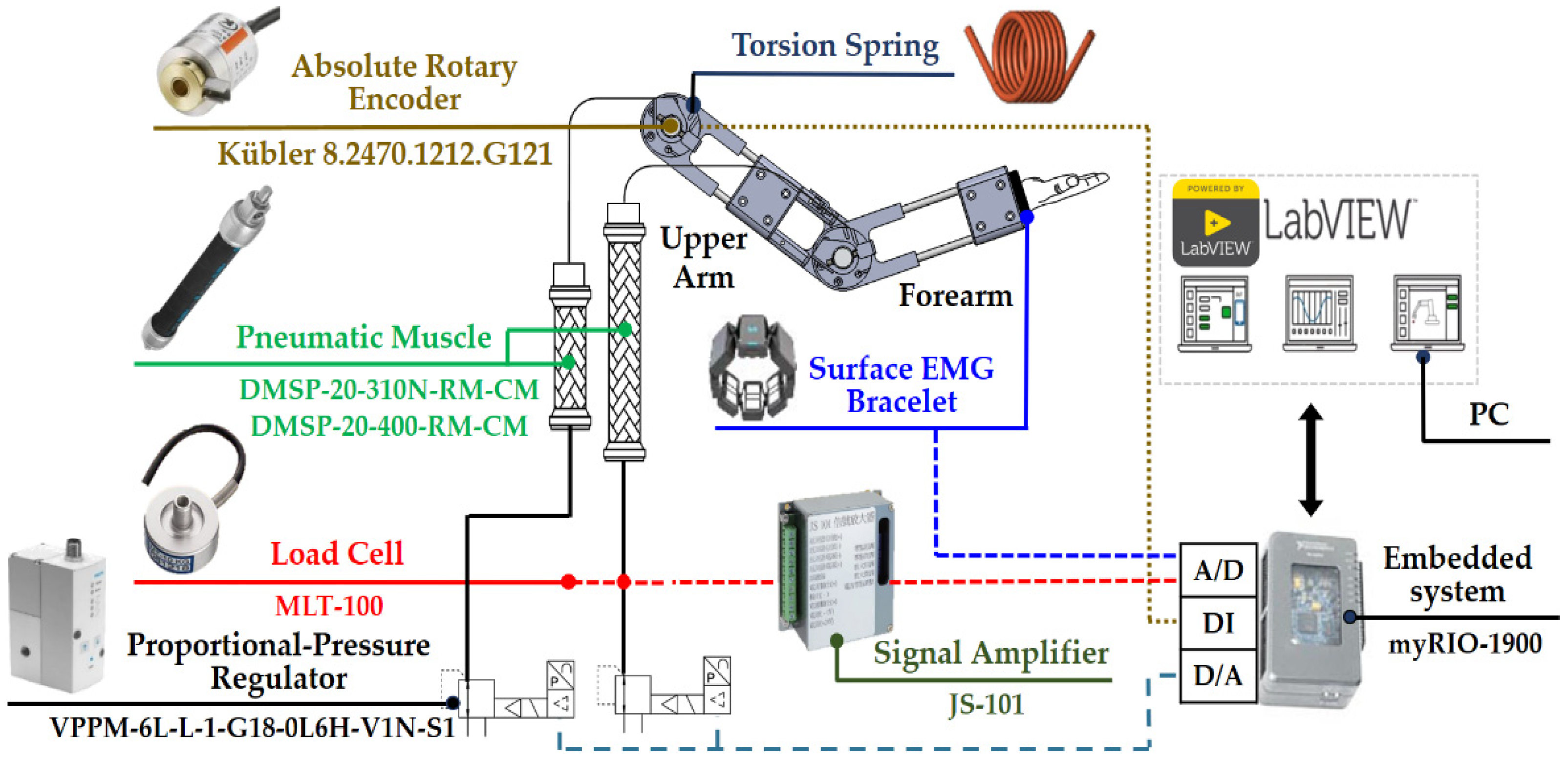
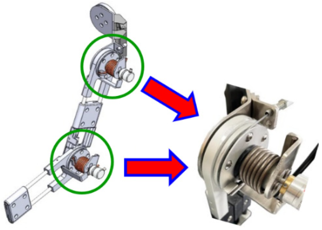
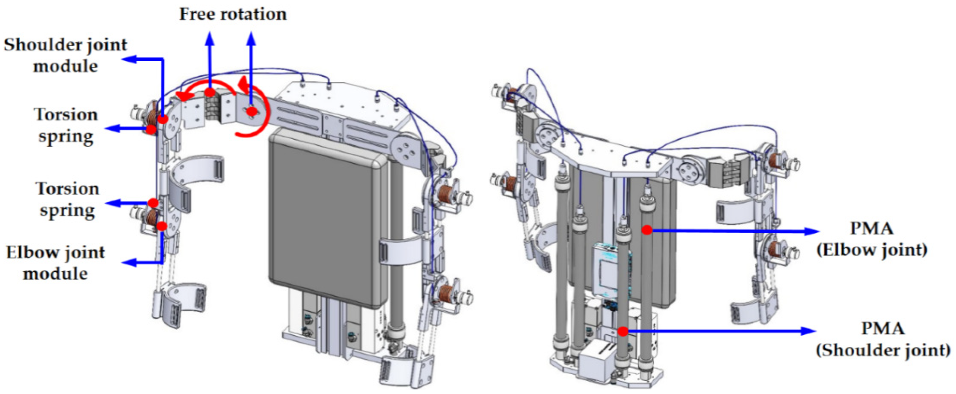
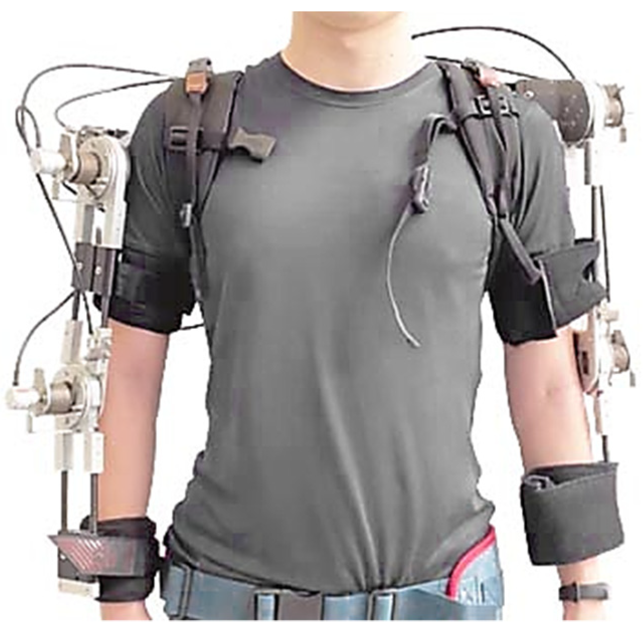
2. Mechanism Design of Upper-Limb Exoskeleton Power Assist System

To help reduce the risk of WMSD in labor works or increase productivity, it is necessary to design an assistive device that is convenient to operate, low cost, lightweight, safe, and easy to wear. Unlike the mechanism designs used in soft robotics in most PMAs, dual-PMAs were used to drive a joint with a pulley. The design of the dual-PMA antagonistic mechanism widely used in the joint drive of soft robots has a bulky overall structure, and the manufacturing cost is relatively high [27]. Therefore, this study aimed to design an innovative wearable UPES for laborers to support their upper limb’s auxiliary force while performing repetitive weight lifting tasks. The drive joint of the present design mainly combines a torsion spring module with the single-PMA via a steel cable and is controlled by a proportional-pressure regulator. The design of the torsion spring module with a single-PMA can replace the design of dual-PMAs with a pulley module. The matching design of the torsion spring module and the PMA can achieve the same driving effect of the joint as the dual-PMA mechanism with the appropriate control strategy. The design of a single-PMA-driven structure can reduce the number of PMAs and proportional-pressure regulators in half, thereby reducing overall volume, weight, and manufacturing costs. The design of the wearable UPES must conform to the motion of the human arm and match the anatomy as closely as possible. However, detailed designs will lead to bulky and complex exoskeleton structures. As shown in Figure 1, this paper proposes a wearable UPES with 4-DOFs according to the required function, mainly including flexion and extension of the shoulder joints and elbow joints on both sides of the arm. Figure 2 displays a photograph of the wearable UPES; its material is mainly aluminum alloy with lightweight and low cost. It consists of two 310 mm (shoulder joint) and two 400 mm (elbow joint) PMAs (the maximum contraction rate is 25% of the length) with four sets of joint rotating pulleys (radius 30 mm) and torsion spring structures. The design dimensions of the upper arm, forearm, and shoulder mechanism were calculated considering the proportional relationship of various human body parts [37], and the telescopic mechanism design was used to adapt to the different sizes of human arms. Each joint comprises a torsion spring module with a single-PMA and is mounted with a high-resolution absolute-type encoder for joint rotation angle monitoring during power assistance.
Figure 3 shows the unilateral wearable UPES layout with a structure similar to that of human upper limbs. We took advantage of the inflation and deflation of the PMA to simulate the motion of flexion of the bones to enable the joint to rotate. The unilateral wearable UPES consists of two joint rotation modules that serve to assist in the rotation of the shoulder and elbow joints. A torsion spring is embedded in each joint for energy storage and replaces the mechanism design of using dual-PMAs with a pulley, as shown in Figure 4. When the assist power force is not activated, there is a torsion spring with a preload angle in the pulley at one end of the wire. The joint can move freely and return to its original position due to the torsion spring. When the assistance power is activated, the pressure is supplied to the PMA through the proportional-pressure regulator. The PMA contracts under pressure, and the pulley is driven to rotate to flex and extend the joints. The wearable UPES has two air source input modes. The first is to supply air directly through the air compressor. The second is configuring a small air tank in the wearable UPES to provide the air pressure source and can be used four times in one filling. The parameters of the torsion spring used in wearable UPES are shown in Table 1. The load cells were installed at the end of the PMAs to measure the provided assist force of the PMA. The measurement signal of the load cell was amplified and transmitted to the embedded system through the analog channel and was compared with the power assist trajectory for feedback control. In the experiment, the amplifier amplifies the measurement signal of the load cell and transmits it to the embedded system through the analog channel to compare and calculate the control error with the set power assist target. The control algorithm can calculate the control voltage of the proportional-pressure regulator based on the control error, which adjusts the pressure to drive the PMA and achieve the assist force closed-loop control of the PMA. Table 2 shows the hardware specifications of the wearable UPES. The system controller adopts the embedded system (myRIO-1900, National Instruments). The measurement and control algorithms required for the experiments are mainly developed in the LabVIEW environment. We used the wearable UPES, as shown in Figure 2, to verify the feasibility of the proposed mechanism and the performance of the controller.

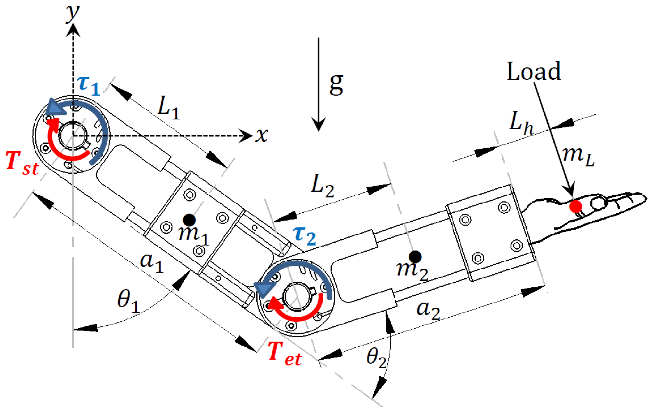
3. System Dynamics Model

The wearable UPES design only assists the shoulder and elbow joints’ flexion and extension degrees of freedom. The others are passive degrees of freedom and only follow the wearer’s movement. The dynamic model of a one-sided wearable UPES is shown in Figure 5; m 1 and m 2 are the masses of the upper arm and forearm, L 1 and L 2 are the distances from the shoulder joint and the elbow joint to the center of mass, m L is the mass of the load, and L h is the distance from the center of mass of the load to the endpoint of the mechanism. The dynamics model of the one-sided wearable UPES is derived using the Lagrange method, and the function is defined as the total energy of the mechanical system. This total energy is the sum of kinetic energy, K , and potential energy, U :
L = U + K .
For a single manipulator with two degrees of freedom, the formula for calculating the kinetic energy, K , is:
K 1 = 1 2 m 1 L 1 2 θ ˙ 1 2 + 1 2 I 1 θ ˙ 1 2 K 2 = 1 2 m s V s 2 + 1 2 I s ( θ ˙ 1 + θ ˙ 2 ) 2 ,
where I 1 is the moment of inertia of the upper arm relative to its center of mass, I s is the moment of inertia of the forearm and the load relative to their common center of mass, θ 1 is the flexion and extension angle of the shoulder joint, θ 2 is the flexion and extension angle of the elbow joint, V s is the common speed of the forearm and the load, and m s is the common mass of the forearm and the load. When L c is defined as the distance between the elbow joint and the common center of mass, then:
L c = m 2 L 2 + m L ( a 2 + L h ) m 2 + m L .
The coordinates and velocity of the endpoint of the one-sided wearable UPES can be expressed as:
x s = a 1 s 1 + L c s 12 y s = a 1 c 1 L c c 12 x ˙ s = a 1 c 1 θ ˙ 1 + L c c 12 ( θ ˙ 1 + θ ˙ 2 ) y ˙ s = a 1 s 1 θ ˙ 1 + L c s 12 ( θ ˙ 1 + θ ˙ 2 ) V s 2 = x ˙ s 2 + y ˙ s 2 ,
where s i = sin θ i ,   c i = cos θ i ,   s i j = sin ( θ i + θ j ) ,   c i j = cos ( θ i + θ j ) .
The potential energy of the one-sided wearable UPES is expressed as:
U = m 1 g L 1 c 1 + m s g ( a 1 c 1 + L c c 12 ) .
Substitute Equations (2)–(5) into Equation (1):
L θ 1 , θ 2 = K 1 + K 2 + U .
Equation (7) is the partial differentiation of L θ 1 , θ 2 to the state variables θ 1 , θ 2 , θ ˙ 1 , θ ˙ 2 , respectively, and they are expressed as:
L θ 1 = m 1 g L 1 s 1 m s g ( a 1 s 1 + L c s 12 )   L θ 2 = ( m s a 1 L c s 2 ) θ ˙ 1 2 ( m s a 1 L c s 2 ) θ ˙ 1 θ ˙ 2 m s g L c s 12 L θ ˙ 1 = m 1 L 1 2 + I 1 + m s a 1 2 + L c 2 + 2 a 1 L c c 2 + I s θ ˙ 1 + m s a 1 L c c 2 + m s L c 2 + I s θ ˙ 2 L θ ˙ 2 = m s a 1 L c c 2 + m s L c 2 + I s θ ˙ 1 + ( m s L c 2 + I s ) θ ˙ 2 .
Differentiating with respect to time for L / θ ˙ 1 and L / θ ˙ 2 , respectively, we can be obtained:
d d t L θ ˙ 1 = m 1 L 1 2 + I 1 + m s a 1 2 + L c 2 + 2 a 1 L c c 2 + I s θ ¨ 1 + m s a 1 L c c 2 + m s L c 2 + I s θ ¨ 2 2 m s a 1 L c s 2 θ ˙ 1 θ ˙ 2 ( m s a 1 L c s 2 ) θ ˙ 2 2 d d t L θ ˙ 2 = m s a 1 L c c 2 + m s L c 2 + I s θ ¨ 1 + m s L c 2 + I s θ ¨ 2 ( m s a 1 L c s 2 ) θ ˙ 1 θ ˙ 2 .
The dynamics equation (Lagrange equation) of the one-sided wearable UPES is:
τ i = d d t L θ ˙ i L θ i i = 1 , 2 ,
where τ i is the generalized moment acting on the ith coordinate, θ i is the generalized coordinate of kinetic energy and potential energy, and θ ˙ i is the corresponding velocity. Substitute Equations (7) and (8) into Equation (9) to obtain the dynamics equation of the one-sided wearable UPES:
τ 1 τ 2 = m 1 L 1 2 + I 1 + m s a 1 2 + L c 2 + 2 a 1 L c c 2 + I s m s a 1 L c c 2 + m s L c 2 + I s m s a 1 L c c 2 + m s L c 2 + I s m s L c 2 + I s θ ¨ 1 θ ¨ 2       . + 0 m s a 1 L c s 2 m s a 1 L c s 2 0 θ ˙ 1 2 θ ˙ 2 2 + 2 m s a 1 L c s 2 0 θ ˙ 1 θ ˙ 2   + m 1 g L 1 s 1 + m s g ( a 1 s 1 + L c s 12 ) m s g L c s 12
The relationship between the moment applied to the joints, the pulling forces of the PMA, and the torques of the torsion springs are:
τ 1 + T s t = F 1 × R 1 τ 2 + T e t = F 2 × R 2 ,
where T s t and T e t are the torques of the torsion springs at the shoulder and elbow; F 1 and F 2 are the pulling forces of the PMAs on the shoulder joint and the elbow joint; R 1 and R 2 are the pulley radius of the shoulder and elbow.
The relationship between the output (contraction) force, F P M A , of the PMA and the pressure difference P P e was derived from [38]:
F P M A = P P e 3 L 2 l 2 4 π n 2 ,
where P is the absolute pressure in the PMA cavity, P e is atmospheric pressure, L is the length of the PMA, l is the length of a single fiber, n is the number of winding turns of a single fiber, and A ¯ = ( 3 L 2 l 2 ) / 4 π n 2 is the equivalent active area of the PMA. The contraction force, F P M A , of the PMA is achieved by controlling the absolute pressure, P , in the PMA cavity through the proportional-pressure regulator. In a single PMA system, the dynamic characteristics of the proportional-pressure regulator are described by the second-order differential equation [39]. The relationship between the input voltage and output pressure is:
P u = K γ ω n s 2 + 2 ξ ω n s + ω n 2
where K γ is the gain of the proportional-pressure regulator, ω n is the natural frequency, u is the input voltage, and ξ is the damping ratio. On substituting Equation (13) into Equation (12), the mathematical model of the PMA is obtained:
F P M A = K γ ω n s 2 + 2 ξ ω n s + ω n 2 u P e 3 L 2 l 2 4 π n 2 .
Conversion of Equation (14) from the frequency domain to the time domain can lead to the relationship between the input voltage and the output force of a single PMA system as:
u t = 4 π n 2 K γ ω n 3 L 2 l 2 F ¨ P M A + 2 ξ ω n F ˙ P M A + ω n 2 F P M A + ω n K γ P e .
The proportional-pressure regulator provides pressure to the PMA, which is measured by the load cell. This tension causes the single-PMA-driven joint to generate respective torques relative to the pulley block at the joint. Only a single-PMA-driven joint is analyzed because the shoulder joint is driven similarly to the elbow joint. Let F P M A = τ / R , F ˙ P M A = τ ˙ / R , F ¨ P M A = τ ¨ / R ; substitute them into Equation (15) and add the torsion spring torque, d ( t ) . Then, the mathematical model of the single-PMA-driven joint can be expressed as:
τ ¨ = 2 ξ ω n τ ˙ ω n 2 τ ω n 2 R 3 L 2 l 2 4 π n 2 P e + K γ ω n R 3 L 2 l 2 4 π n 2 u t + d ( t ) .
Define the states as ( x 1 , x 2 ) = ( τ , τ ˙ ) , and the state equation of a single-PMA-driven joint can be expressed as:
x ˙ 1 = x 2 x ˙ 2 = f x , t + b x , t u t + d ( t ) ,
where f x , t = 2 ξ ω n x 2 ω n 2 x 1 [ ω n 2 R 3 L 2 l 2 ] P e / 4 π n 2 is the nonlinear dynamics of the single-PMA-driven joint, b x , t = [ K γ ω n R ( 3 L 2 l 2 ) ] / 4 π n 2 is the gain parameter, and u t is the control signal of the proportional-pressure regulator.

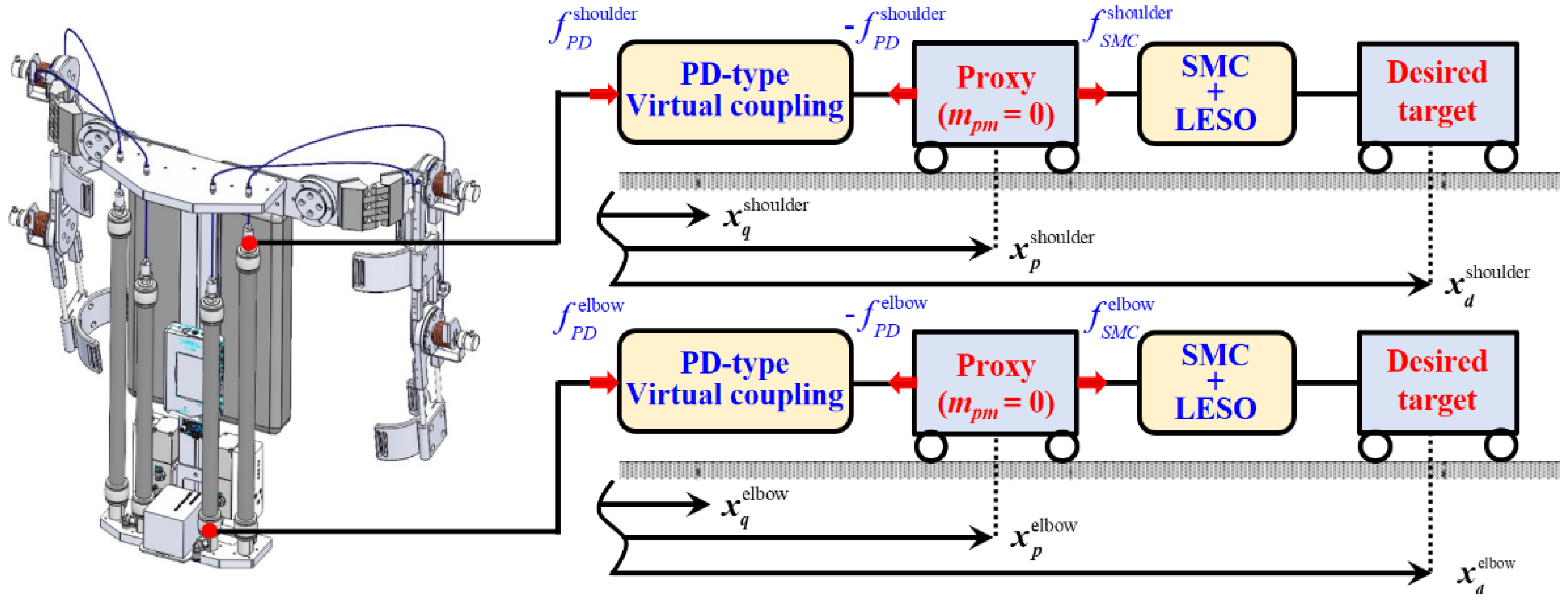
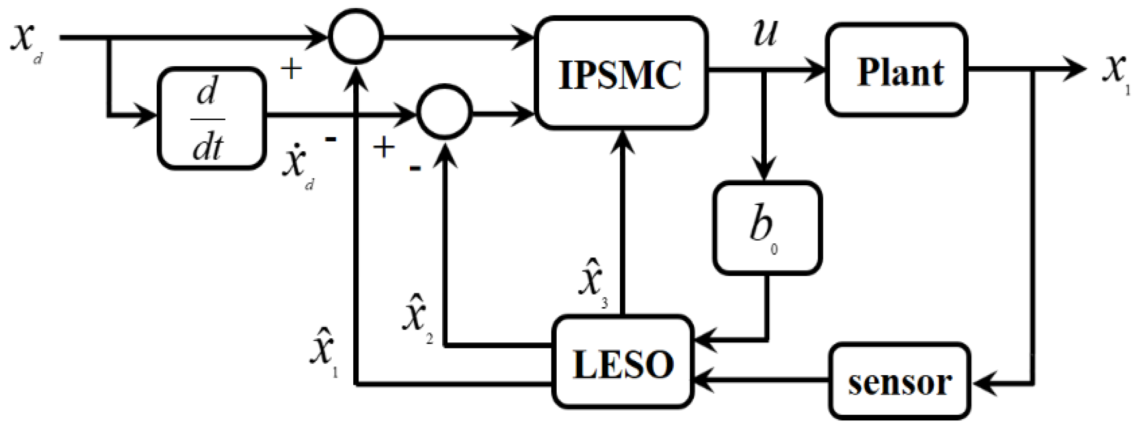
4. Controller Design

With its advantages of easy implementation, accurate tracking, and safe recovery when the system is under external disturbances, PSMC has been successfully applied in various fields, especially in soft robotics. However, the stability of the original PSMC is not well addressed [40]. Furthermore, most previous works assumed that all states of the system are measurable and focused on demonstrating that the closed-loop dynamics are passive to compensate for the presence of disturbances [28]. To this end, this study used IPSMC-LESO to address the inability to measure all system states, load changes, and the interference effects of different wearers, making it difficult to control the power assist of wearable UPES. LESO can simultaneously estimate all system states and total disturbances (i.e., extended state) in real-time; it treats non-linearity, uncertainty, and various disturbances as an extended state [41]. This methodology simplifies the proof of the stability of the dynamic system and simplifies the derivation. This section presents the design procedure and stability analysis of the IPSMC-LESO for the wearable UPES’s single-PMA-driven joint.

4.1. Design of Linear Extended State Observer

The IPSMC is a sliding-mode-like controller for application to second-order systems [40]. To estimate the total disturbance of a single-PMA-driven joint in real-time, we choose f ( x , t ) + ( ( b ( x , t ) ) b 0 ) u ( t ) + d ( t ) F as the extended state of Equation (17) and derived the following relation by defining x = τ , τ ˙ , F T = x 1 , x 2 , x 3 T R 3 as the extended state vector.
x ˙ 1 = x 2 x ˙ 2 = x 3 + b 0 u x ˙ 3 = w
where b 0 is the nominal value of b ( x , t ) , and x ˙ 3 = w is the rate of change of the total disturbance.
Assumption 1
([42]). The unknown total disturbance, F , is continuously differentiable for the system (18), and the inequality of w η is satisfied, where η > 0 .
Based on Equation (18), the LESO of the wearable UPES’s single-PMA driven joint is designed as below [27]:
x ^ ˙ 1 = x ^ 2 β 1 ( x ^ 1 x 1 ) x ^ ˙ 2 = x ^ 3 β 2 ( x ^ 1 x 1 ) + b 0 u x ^ ˙ 3 = β 3 ( x ^ 1 x 1 )
where x ^ = x ^ 1 , x ^ 2 , x ^ 3 T represents the observed state vector and β i ( i = 1 , 2 , 3 ) are the tunable observer parameters. Defining that:
x ˜ 1 = x ^ 1 x 1 x ˜ 2 = x ^ 2 x 2 x ˜ 3 = x ^ 3 x 3 .
Taking the derivative of Equation (20) with respect to time, and substituting Equations (18) and (19), the dynamic equations of estimating error between LESO and system states can be summarized below:
x ˜ ˙ 1 = x ˜ 2 β 1 x ˜ 1 x ˜ ˙ 2 = x ˜ 3 β 2 x ˜ 1 x ˜ ˙ 3 = β 2 x ˜ 1 w .
Presenting Equation (21) in the matrix form yields:
x ˜ ˙ = A r x ˜ r + B r w
where A r = β 1 1 0 β 2 0 1 β 3 0 0 , x ˜ = x ˜ 1 x ˜ 2 x ˜ 3 T , Β r = 0 0 1 T .
Theorem 1:
Assuming that w in the estimating error equations is bounded, for which H 1 > 0 such that w H 1 , then there exists H 2 > 0 such that lim t x ˜ r 2 H 2 , that is, there exists LESO, which makes the estimating error bounded. Furthermore, the upper limit of the estimating error decreases progressively while eigenvalues of LESO increase [27].
Proof. 
In the first place, selecting positive eigenvalues of A r , 0 < λ i λ j ( i , j = 1 , 2 , 3 ). Hence:
λ I 3 A r = i = 1 3 ( λ + λ i ) .
In this situation, A r is a nonsingular matrix such that there exists a nonsingular matrix, L , yielding:
e A r t = L e λ 1 t 0 0 0 e λ 2 t 0 0 0 e λ 3 t L 1 .
For any positive value t > 0 , taking the norm form gives:
e A r t L L 1 e λ 1 t 0 0 0 e λ 2 t 0 0 0 e λ 3 t = ρ e λ 1 t
where ρ = L L 1 , and ρ is a constant when λ i ( i = 1 , 2 , 3 ) are determined from A r . Solving Equation (22), gives:
x ˜ ( t ) = e A r t x ˜ ( 0 ) + 0 t e A r ( t τ ) Β r w ( τ ) d τ .
From definitions of the vector norm, 2 , and matrix norm, , the following relationship can be obtained:
x ˜ ( t ) 2 e A r t x ˜ ( 0 ) 2 + 0 t e A r ( t τ ) B r w ( τ ) d τ 2 3 e A r t x ˜ ( 0 ) 2 + 0 t 3 e A r ( t τ ) B r 2 w ( τ ) 2 d τ 3 ρ x ˜ ( 0 ) 2 e λ 1 t + 3 γ H 1 λ 1 1 e λ 1 t .
From Equation (27), the estimating error of LESO when t will converge to:
lim t x ˜ 2 3 ρ H 1 λ 1 = H 2 .
From Equation (28), the final estimating error is bound, and its upper limit decreases progressively while the eigenvalues of LESO increase. In this study, the same eigenvalue was chosen, λ i = ω o ( i = 1 , 2 , 3 ), where ω o is the observer bandwidth. Therefore, the observer bandwidth, ω o , becomes the only adjusting parameter of the LESO, thereby reducing the parameter-adjusting effort [43]. □

4.2. Improved Proxy-Based Sliding Mode Controller Integrated with Linear Extended State Observer

The principle of the proposed IPSMC-LESO is illustrated in Figure 6. The actual controlled object of the IPSMC is connected to a virtual object, called a proxy, utilizing a proportional derivative (PD)-type virtual coupling (a PD controller). Therefore, the PD controller generates the interaction force, f P D , between the actuator and the proxy. Meanwhile, the proxy is also controlled by an SMC with LESO, which imposes the force, f S M C , to track the desired power assist target. As shown in Figure 6, x p and x ˙ p are the proxy’s position and velocity, and x d , x ˙ d , and x ¨ d are the desired position, velocity, and acceleration, respectively. Before designing the IPSMC-LESO, we first defined the two sliding surfaces, as below:
s p = x ˙ d x ˙ p + λ n ( x d x p ) s q = x ˙ d x ^ ˙ q + λ n ( x d x ^ q ) .
The SMC with LESO used to control the virtual proxy is defined as:
f S M C = σ sgn ( s p ) k p ( x p x ^ q ) + m p m x ¨ d + m p m λ n ( x ˙ d x ˙ p ) k d ( x ˙ p x ^ ˙ q ) + 1 b 0 [ F ^ + k p ( x p x ^ q ) + k d ( x ˙ p x ^ ˙ q ) , + λ n ( x ˙ d x ^ ˙ q ) + x ¨ d ]
where sgn ( ) is the signum function, x ^ q is an estimate of the actual output of the controlled object, m p m denotes the proxy mass, and σ > 0 and λ n > 0 are designed control gains. For the real controlled object to approach the proxy object, the force generated by the PD controller is:
f P D = 1 b 0 F ^ + k p ( x p x ^ q ) + k d ( x ˙ p x ^ ˙ q ) + λ n ( x ˙ d x ^ ˙ q ) + x ¨ d
where f P D is the control force acting on the controlled object by IPSMC-LESO, F ^ is the total disturbance of the single-PMA-driven joint estimated by the LESO, and k p and k d are designed positive gains of the PD controller. Considering the proxy presented in Figure 6, according to Newton’s second law of motion, the equation of action can be given by:
m p m x ¨ p = f S M C   f P D
When the controller is implemented directly using Equations (30) and (31), the movement of the virtual proxy mass must be simulated in software. In practical applications, Kikuuwe et al. [18] implemented them by setting the proxy mass in Equation (32) to zero. As a result, substituting Equations (30) and (31) into Equation (32) gives:
m p m x ¨ p = σ sgn ( s p ) k p ( x p x ^ q ) + m p m x ¨ d + m p m λ n ( x ˙ d x ˙ p ) k d ( x ˙ p x ^ ˙ q ) .
Equation (33) can be expressed as:
x ˙ p = 1 k d σ sgn ψ k p ( x p x ^ q ) + k d x ^ ˙ q ,
where ψ = k d ( x ˙ d x ^ ˙ q ) + k d λ n ( x d x p ) + k p ( x p x ^ q ) σ . Substituting Equation (34) into Equation (31), the IPSMC-LESO can be applied to the single-PMA-driven joint as:
f I P S M C - L E S O = f P D = 1 b 0 F ^ + λ n ( x ˙ d x ^ ˙ q ) + x ¨ d + σ sgn ψ
where f I P S M C - L E S O is the actual output force of the IPSMC-LESO. The IPSMC-LESO can be viewed as an alternative to the SMC and an extension of PD control. The main benefits are that small tracking errors can be remedied by the well-tuned PD controller (determined by control gains k p and k d ). Large tracking errors can be rapidly recovered from the SMC using the control parameter γ . Therefore, IPSMC-LESO enables accurate tracking and safe interaction. The IPSMC-LESO control block diagram of the single-PMA-driven joint is shown in Figure 7.

4.3. Stability Analysis

Lyapunov stability theory was used to analyze the stability of IPSMC-LESO in wearable UPES control. We chose the following Lyapunov candidate function as:
V = 1 2 m p m s p 2 + 1 2 s q 2 + 1 2 ( k p + k d λ n ) ( x p x ^ q ) 2 .
Differentiating both sides of Equation (36) for time and substituting Equations (29) and (33) into V ˙ , the derivation of the Lyapunov candidate function is obtained as:
V ˙ = s p m p m [ x ¨ d x ¨ p + λ n ( x ˙ d x ˙ p ) ] + s q [ x ¨ d x ^ ¨ q + λ n ( x ˙ d x ^ ˙ q ) ] + ( k p + k d λ n ) ( x p x ^ q ) ( x ˙ p x ^ ˙ q ) = s p [ σ sgn ( s p ) + k p ( x p x ^ q ) + k d ( x ˙ p x ^ ˙ q ) ] + s q [ x ¨ d x ¨ q x ˜ ¨ q + λ n ( x ˙ d x ^ ˙ q ) ] + k p ( x p x ^ q ) ( x ˙ p x ^ ˙ q ) + k d λ n ( x p x ^ q ) ( x ˙ p x ^ ˙ q ) = s p [ σ sgn ( s p ) + k p ( x p x ^ q ) + k d ( x ˙ p x ^ ˙ q ) ] + s q [ x ¨ d F b 0 u x ˜ ¨ q + λ n ( x ˙ d x ^ ˙ q ) ] + k p ( x p x ^ q ) ( x ˙ p x ^ ˙ q ) + k d λ n ( x p x ^ q ) ( x ˙ p x ^ ˙ q ) = s p [ σ sgn ( s p ) + k p ( x p x ^ q ) + k d ( x ˙ p x ^ ˙ q ) ] + s q [ F + F ^ x ˜ ¨ q k p ( x p x ^ q ) k d ( x ˙ p x ^ ˙ q ) ] + k p ( x p x ^ q ) ( x ˙ p x ^ ˙ q ) + k d λ n ( x p x ^ q ) ( x ˙ p x ^ ˙ q ) = σ s p k p λ n ( x p x ^ q ) 2 k d ( x ˙ p x ^ ˙ q ) 2 0 .
From Equations (36) and (37), we know the Lyapunov candidate function, V > and V ˙ 0 . A r is a nonsingular matrix with positive eigenvalues, and the total disturbance, F , is bounded (based on Assumption 1), therefore, the observer states x ^ x as t . Thence, the stability of the single-PMA-driven joint around the equilibrium point x e = [ s p ( 0 ) , s q ( 0 ) , x p ( 0 ) x q ( 0 ) ] = 0 under the compensation of IPSMC-LESO is demonstrated in Lyapunov’s method.

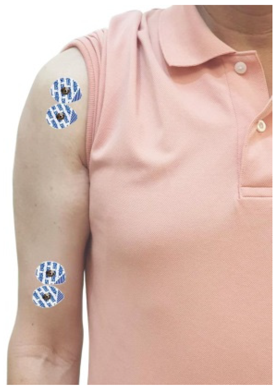
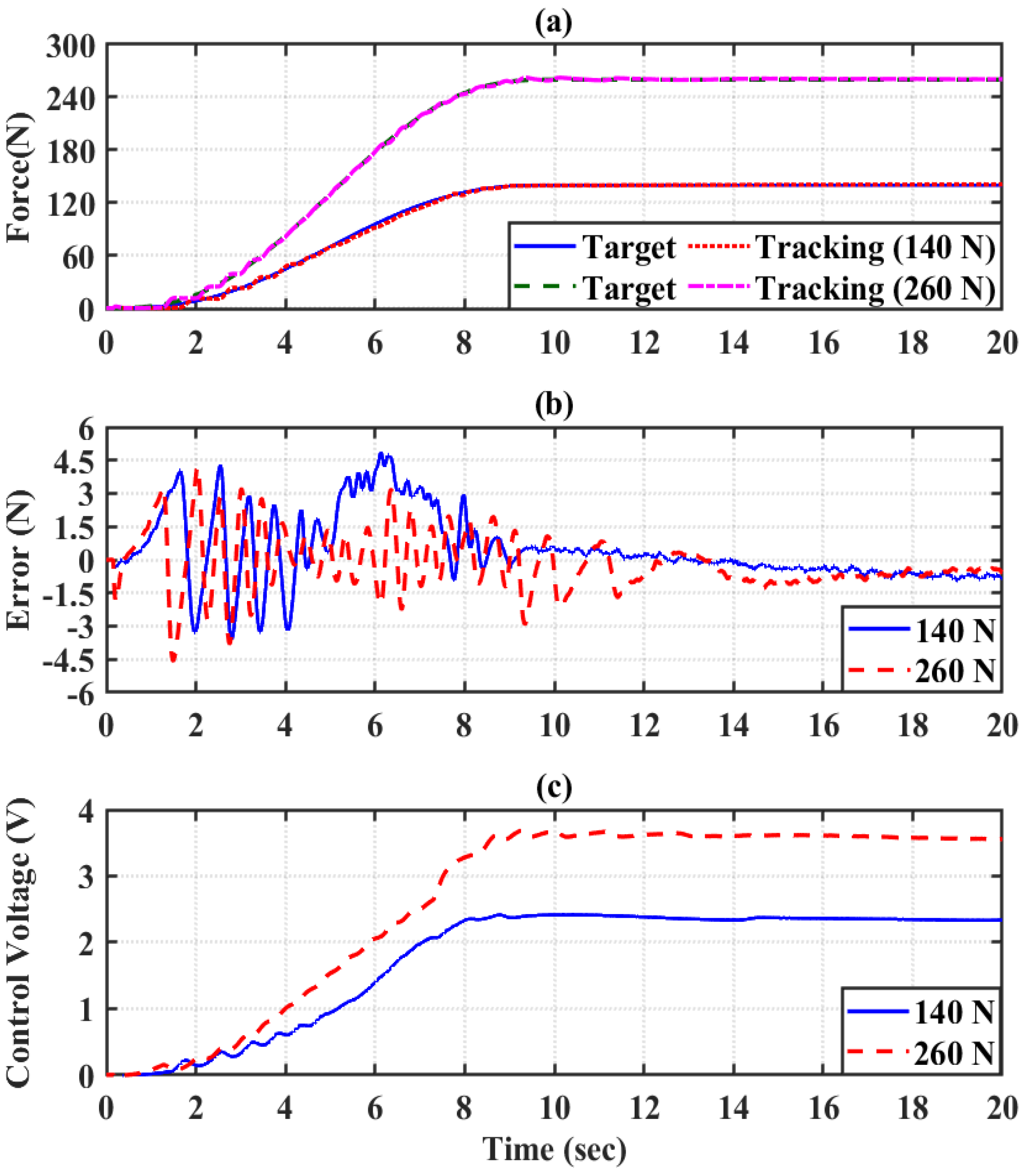
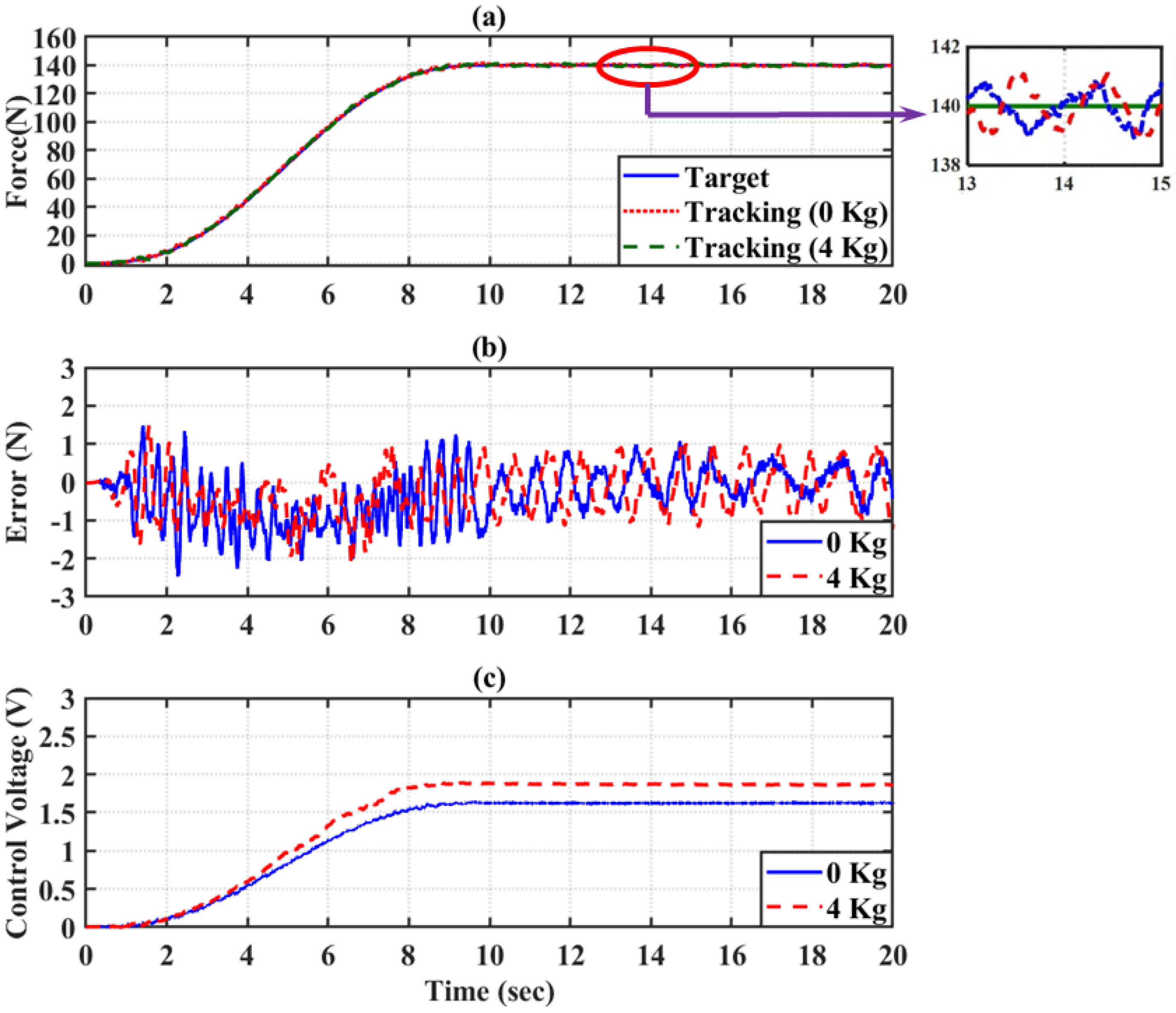
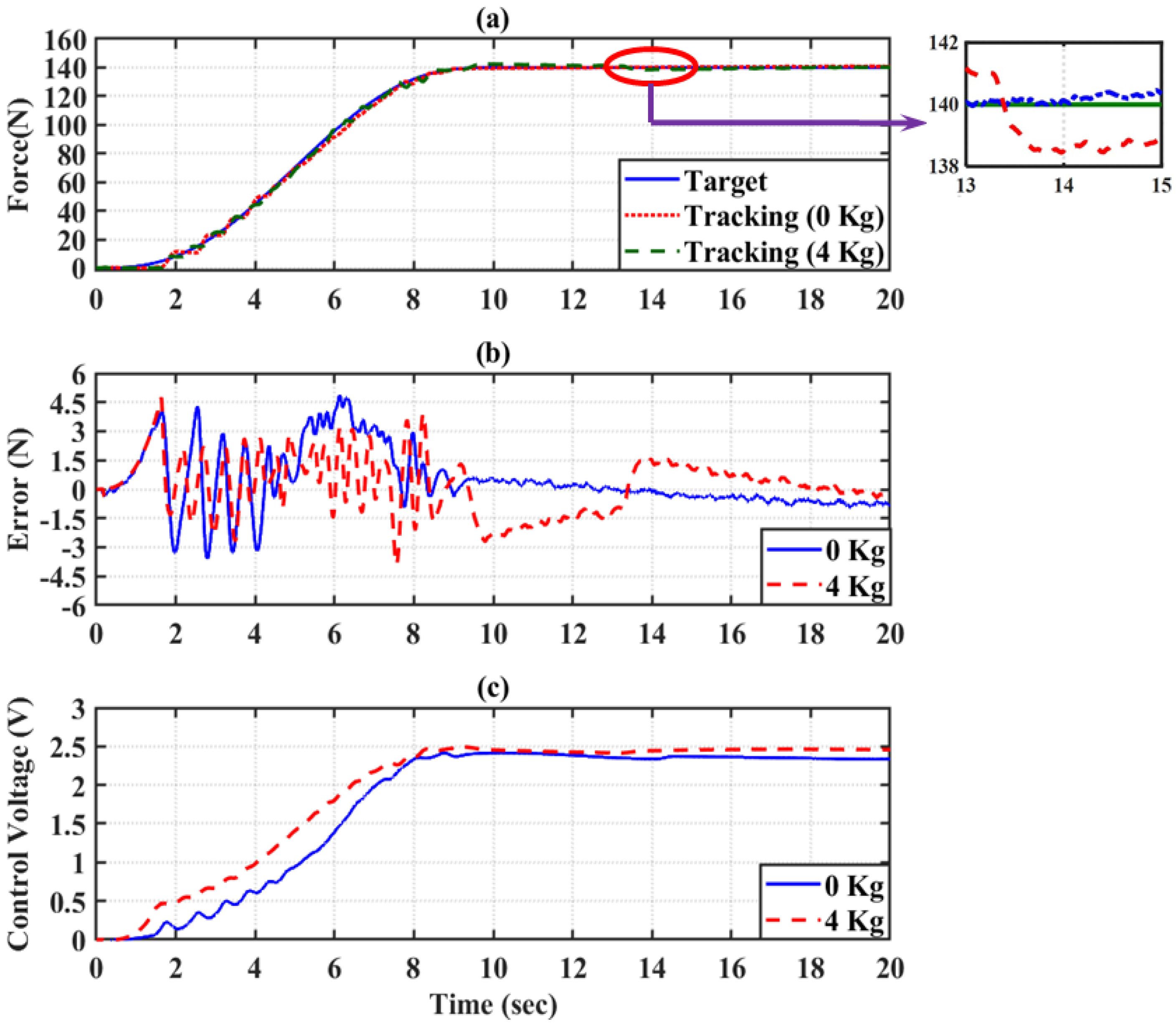
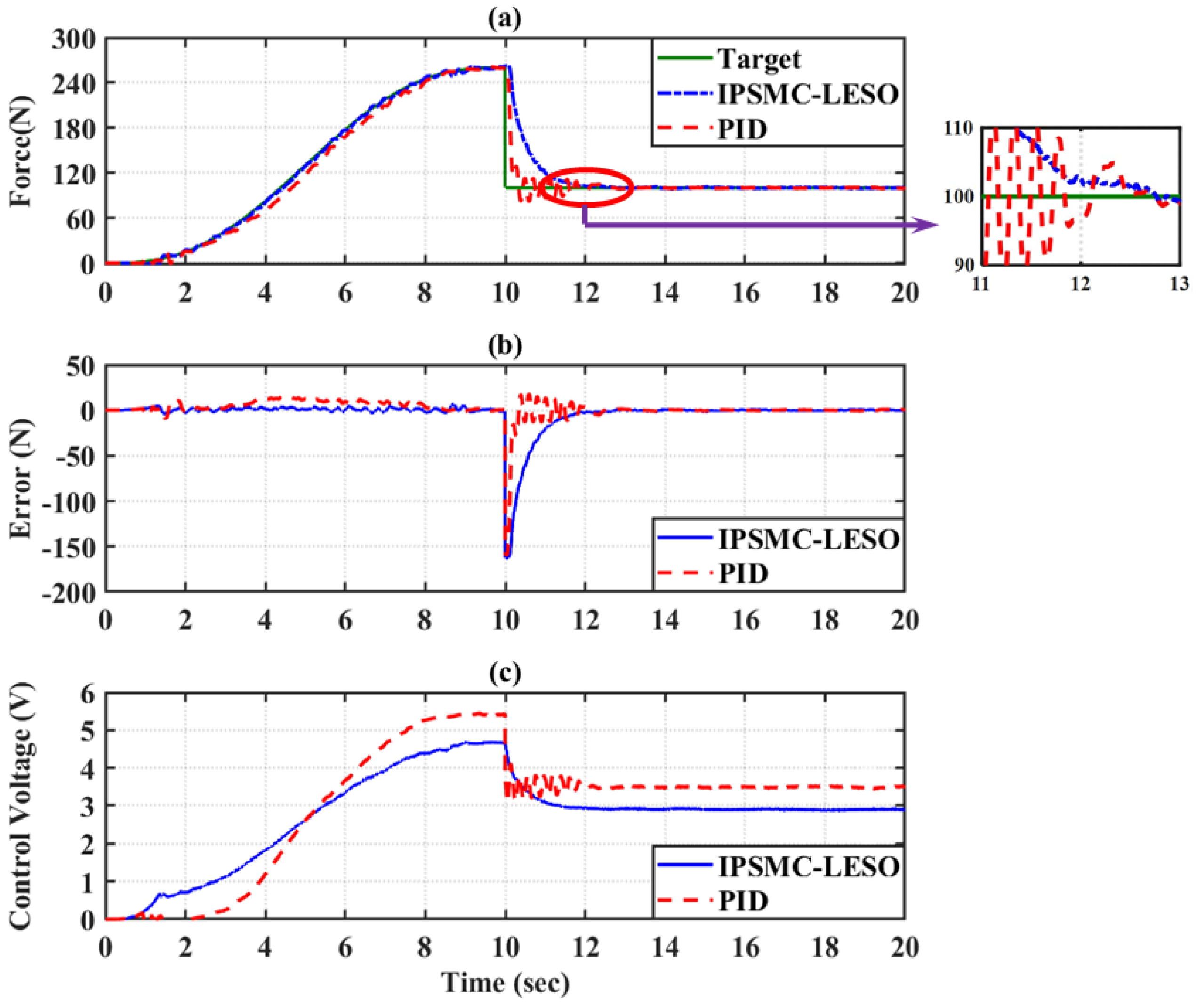
5. Experimental and Discussions

To verify the power assistance effect of the designed wearable UPES, control experiments were performed. For the single-PMA-driven joint controller design for a wearable UPES, the power assist force must be slow and smooth to ensure comfortable and safe interaction between the device and the user. In the experiment, the fifth-order polynomial function was used to plan the power assist trajectory to avoid excessive oscillation of the transient response caused by the saturation of the control voltage due to the significant error. The initial (i.e., x ˙ d f o r c e ( t = 0 ) , and x ¨ d f o r c e ( t = 0 ) ) and final (i.e., x ˙ d f o r c e ( t = t f ) , and x ¨ d f o r c e ( t = t f ) ) were all zero. The fifth-degree trajectory equation was designed as follows [44]:
x d f o r c e ( t ) = h 10 t t f 3 15 t t f 4 + 6 t t f 5 ,   0 t < t f h   , t t f ,
where h is the target of power assist, t f is the time required to reach the target of the power assist, x d f o r c e ( t ) denotes the power assist trajectory, and t is the running time. In this study, the sampling frequency was set at 200 Hz.

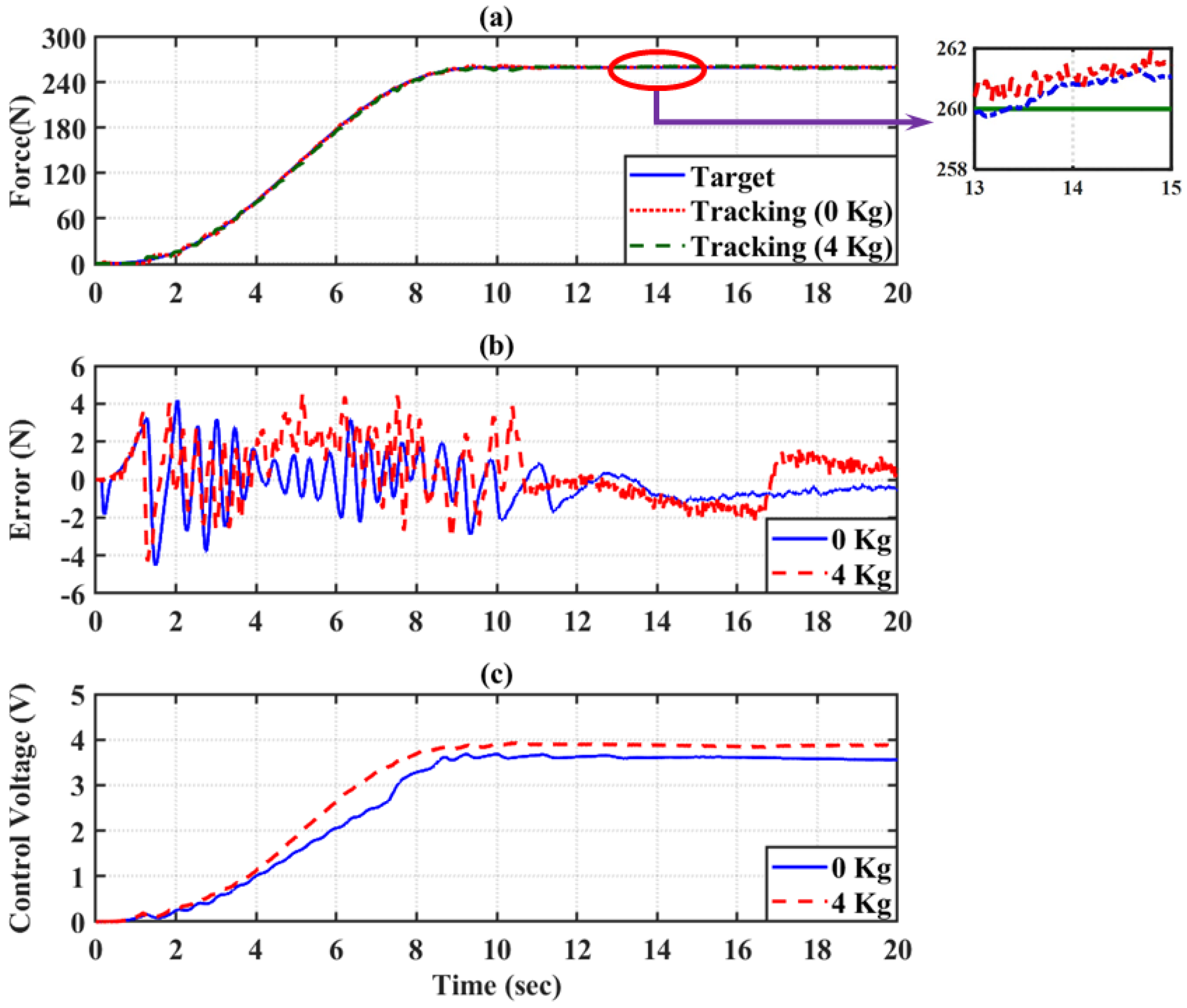
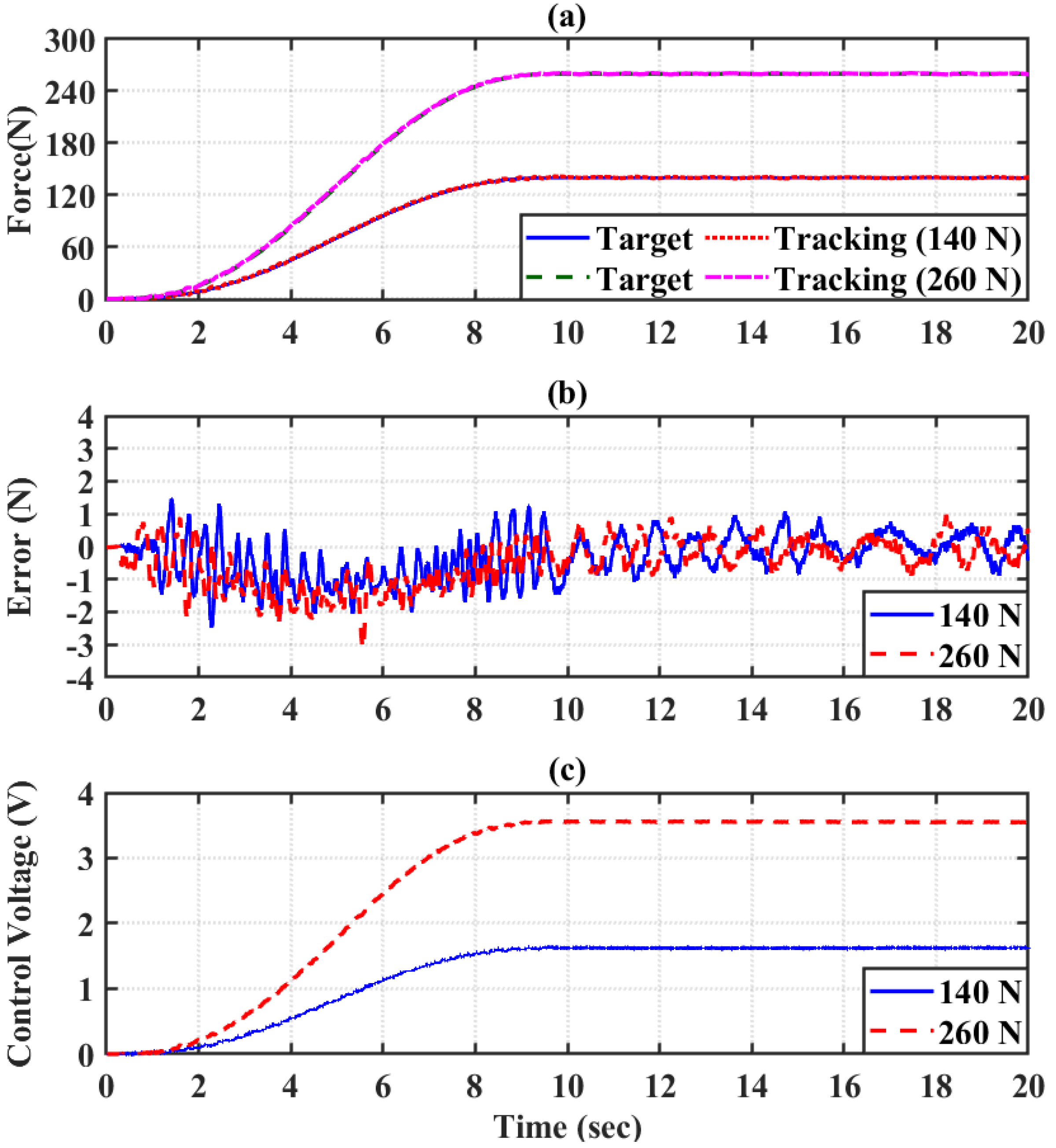
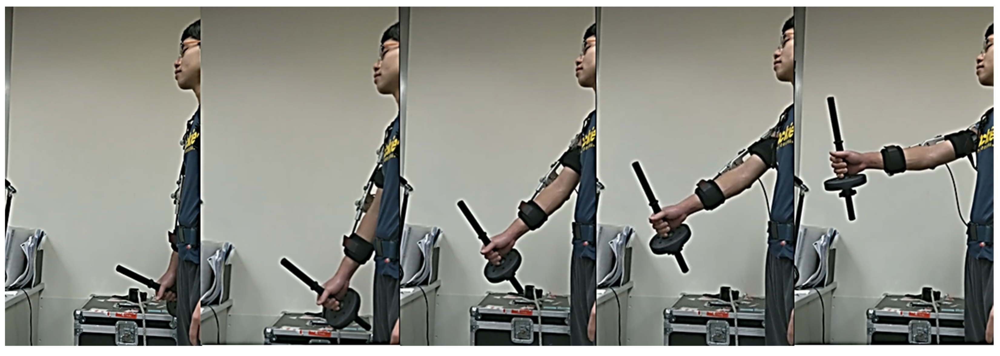
5.1. Power Assist Control Experiment

First, no-load tests were performed to ensure the safety and compliance of wearing the UPES under IPSMC-LESO compensation. Then, power-assisted experiments were carried out by taking the foundry fields as an example to verify whether the wearable UPES can provide the wearer with an effective, stable, and flexible human-machine interaction under the closed-loop control. The no-load test experiment adopts the fifth-order polynomial function Equation (38) as the power assist trajectory, where t f = 10 . The parameters of IPSMC-LESO for power assist control are mentioned in Table 3. Figure 8 and Figure 9 show the experimental results of power assist control of 140 N and 260 N for the shoulder and elbow joint under no-load conditions, respectively. Table 4 shows the total performance of the wearable UPES under IPSMC-LESO compensation at no-load. From Table 4, we can see that the maximum absolute error of the shoulder joint was within 3.2 N, and the root mean square error was within 0.8 N; the maximum absolute error of the elbow joint was within 4.9 N, and the root mean square error was within 1.6 N. These experimental results show that the wearable UPES can achieve an excellent power assists effect under the compensation of IPSMC-LESO.
After the no-load test results were confirmed, the following load experiments were performed for the needs of different power assisting targets in various fields. For example, taking a foundry worker and applying a long tube to the end of the wrist with a weight (approximately 4 kg). The KIM-MHO inspection method proposed in [45] was used to evaluate the working time, force rating points, grasping conditions, arm positions, working conditions, and working postures Each key indicator is given a different rating score range according to its rating content and importance, and the higher the rating score, the greater the hazard risk. A simple weighted calculation through the table and a quick assessment indicated that the risk score of workers in the actual workplace was 45 points; it is a high-load environment and needs improvement. The detailed scoring results are shown in Table 5. Therefore, in this section, this situation was simulated and experiments with different assisting targets were conducted under a 4 kg load to confirm whether the wearable UPES can achieve a good power assisting effect under the compensation of IPSMC-LESO. Controller parameters are the same as in Table 3. Figure 10 and Figure 11 are the results of the shoulder joint carrying out 140 N and 260 N power assist control experiments, respectively, when the user wore UPES and bore a weight of 4 kg. Figure 12 and Figure 13 are the results of the elbow joint carrying out 140 N and 260 N power assist control experiments, respectively, when the user wore UPES and bore a weight of 4 kg. From Table 6, the maximum absolute error of the shoulder joint was within 2.5 N, and the root mean square error was within 0.8 N; the maximum absolute error of the elbow joint was within 4.8 N, and the root mean square error was within 1.6 N. The analysis of the above-mentioned experimental results shows that the wearable UPES can achieve an excellent power assists effect under the compensation of IPSMC-LESO.

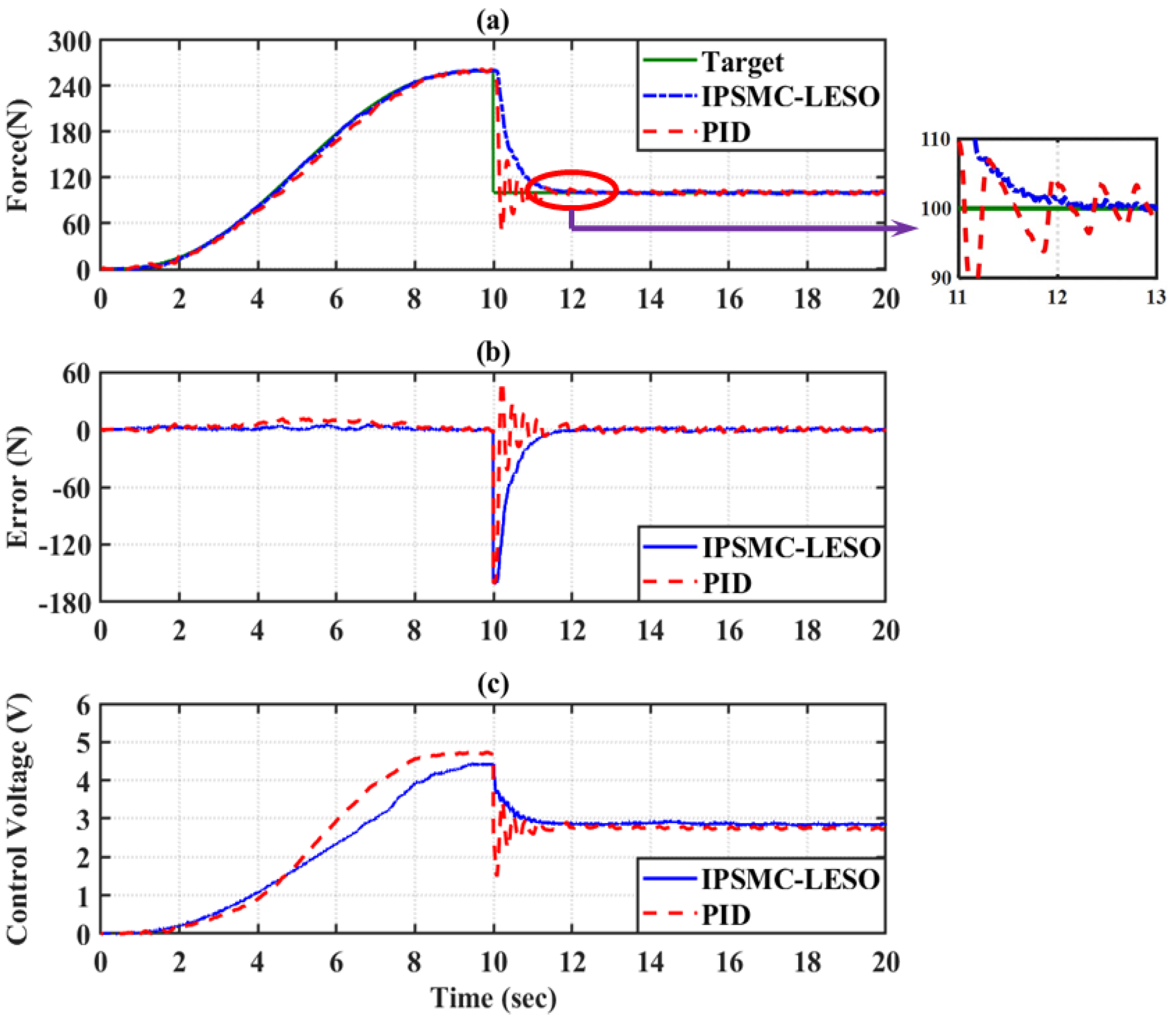
5.2. Discontinuity Recovery Performance Test and Comparison

The ability of the controller to recover from discontinuities possibly caused by communication failures or external disturbances and interactions was examined. We established the mutation trajectory of Equation (39) and then tested the intermittent recovery performance of the shoulder and elbow joint by IPSMC-LESO and PID, respectively. The IPSMC-LESO parameters were the same as in Table 3. The PID controller parameters are mentioned in Table 7.
x d f o r c e ( t ) = 260 10 t t f 3 15 t t f 4 + 6 t t f 5 ,   0 t < 10   100   ,   t 10 .
Figure 14 and Figure 15 illustrate the most critical attributes of IPSMC-LESO: the slow and smooth response to sudden changes in the desired trajectory. Clearly, there was little chattering in the tracking trajectory when the IPSMC-LESO was used. The proposed IPSMC-LESO performed the same as the PID when the target trajectory was continuous and smooth, and the proposed scheme did not affect the position control performance. However, when unforeseen events lead to a large positional discontinuity, the PID control can produce an overshoot that can cause some oscillations, which is not conducive to system safety. Thus, the PID cannot simultaneously obtain safety and good tracking performance. In contrast, the proposed IPSMC-LESO injects suitable damping to recover smoothly from the discontinuity. The IPSMC-LESO can thus be used to smooth the response of the system to unanticipated events while still achieving outstanding tracking performance in normal situations. Most traditional methodologies cannot do both simultaneously. In the case of PID, for example, lowering the gains may ameliorate safety but will decrease the performance. In theory, a high increase in the D-gain can limit joint velocity, but this is not practically feasible due to noise in the velocity signals. Thus, the IPSMC-LESO can guarantee the safety of the wearable UPES by canceling the overshoot during the tracking task.

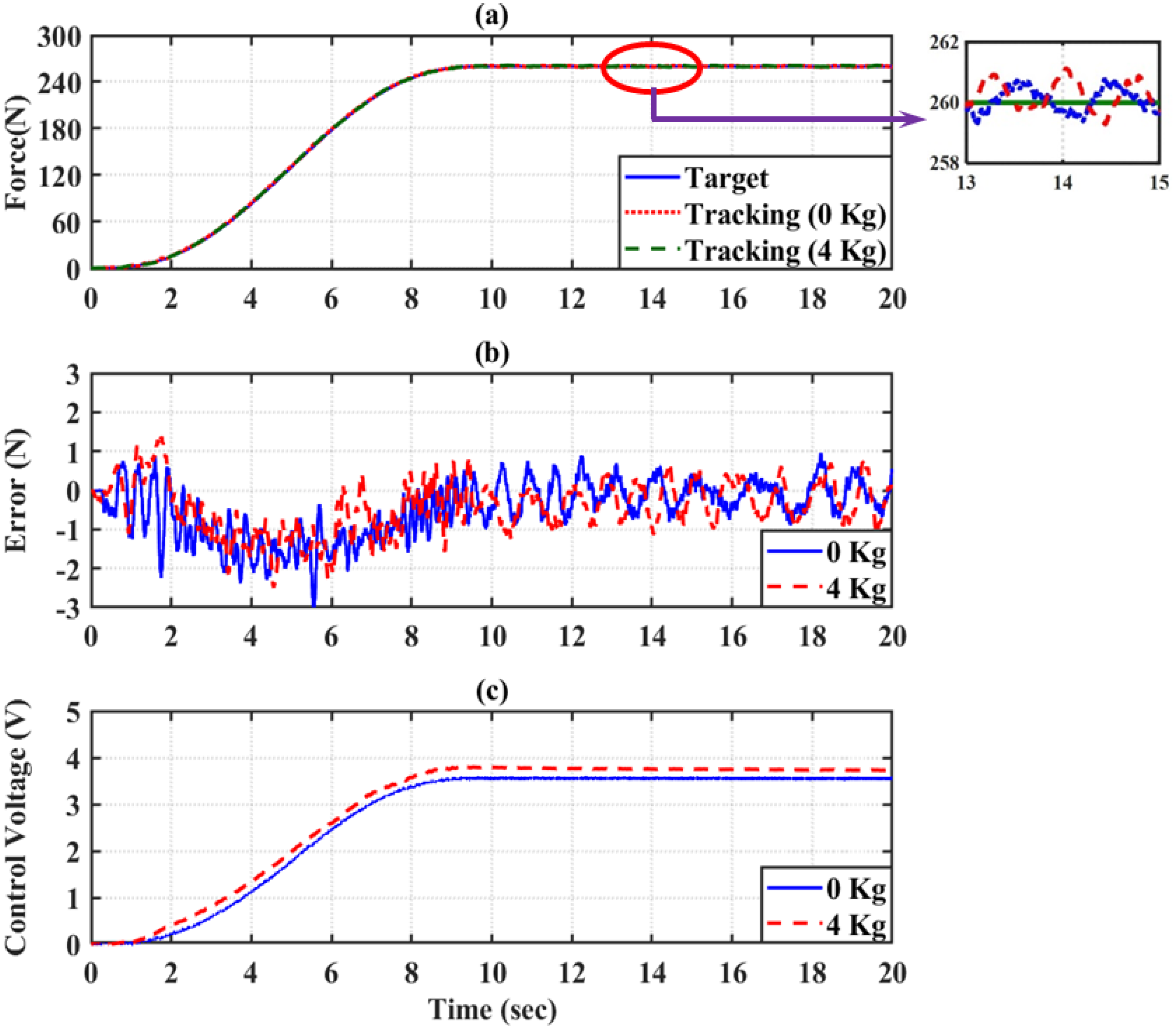
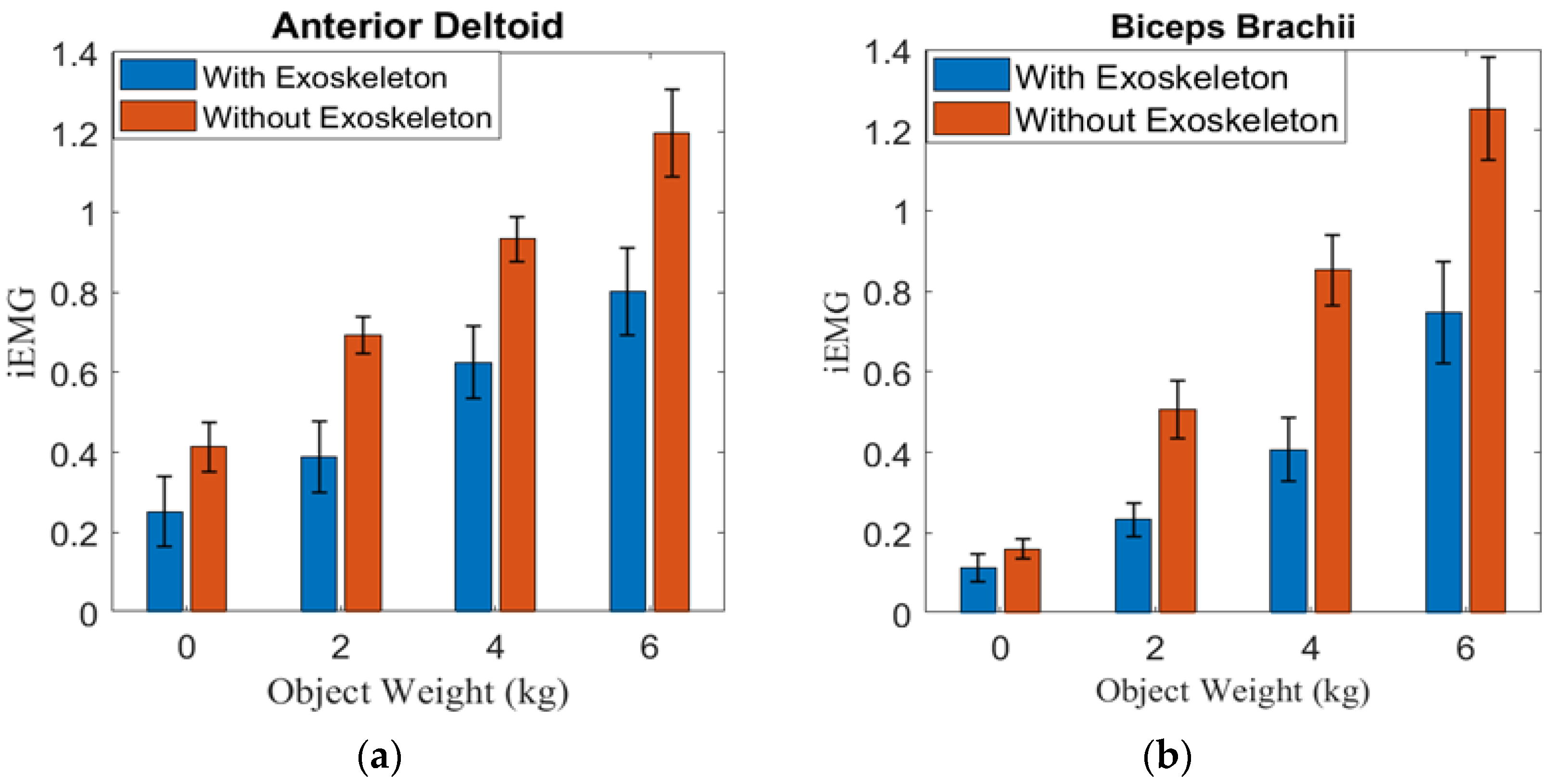
5.3. The Effect of Auxiliary Force

To test the actual power assisting effect of wearing the wearable UPES, we verified the result by measuring the sEMG signals of the anterior deltoid and biceps brachii of the upper limb of the wearer. This experiments used the sEMG instrument of Shimmer Company. Four healthy men were tested in the experiment. The subjects were asked to lift 0, 2, 4, and 6 kg of bar plates with their upper limbs both with and without wearing the wearable UPES. The number of lifts was repeated three times, and the interval between each experiment was 1 min. The upper limb lift process is shown in Figure 16. Non-invasive surface electrode patches and button-type electrode wires were used for measurement. The actual patch positions, as mentioned earlier [36], were respectively attached to the anterior deltoid and biceps brachii, as shown in Figure 17.
To compare sEMG signals in different subjects with and without wearable UPES, a standardization technique was used to calculate the iEMG, which helps to assess muscle activity levels [46]. The value of iEMG is defined as the area under the curve of the rectified sEMG signal that can be simplified and expressed as the summation of the absolute values of the EMG amplitude [47], and the calculation formula is:
i E M G = 1 w k = 1 w x k ,
where x k is the EMG value of the kth sampling point and w is the number of sampling points. The experiments were analyzed by sEMG signal to verify whether it could effectively reduce the iEMG value under the wearable UPES action. In this study, the sEMG device of the Shimmer 3 from Shimmer Sensing Company was used to measure the sEMG of the subjects’ arms. The sampling frequency of the Shimmer 3 is 2048 Hz. The sEMG measure data of the four subjects were analyzed and evaluated through iEMG value. The height and weight of the four subjects are shown in Table 8. The iEMG values of the experimental results for four healthy men are shown in Figure 18. The results show that the iEMG of the anterior deltoid and biceps brachii decreased when the subjects performed the load test. According to the auxiliary benefit formula of Equation (41) [36], when the subjects wore the wearable UPES to lift the load of 0, 2, 4, and 6 kg, the iEMG power assisting benefit of the anterior deltoid was in the range of 33% to 44%. The iEMG power assisting benefit of the biceps brachii was in the range of 30% to 54%. Therefore, it can be proved that the innovative wearable UPES developed in this study can reduce the bearing force of the worker’s upper limb and prevent the worker’s injury under the compensation of IPSMC-LESO.
E e f = 1 I E X I U N E X ,
where I E X is the EMG signals of wearing the wearable UPES, I U N E X is the EMG signals of the unworn wearable UPES, and E e f is the power assisting benefit.

6. Conclusions

An innovative 4-DOF wearable UPES was developed, which provides power assistance to the shoulder and elbow joints. Each joint is driven in one-way actuation by a torsion spring module with a single-PMA via a steel cable. Compared with the traditional drive method of using dual-PMAs with a pulley for antagonistic pull, each joint can reduce one PMA and proportional-pressure regulator. Therefore, the wearable UPES is a straightforward design and is low cost, lightweight, portable, and safe. An IPSMC-LESO joint controller was proposed against the time-varying characteristics of PMAs and the non-linear movement between joint flexion and extension of wearable UPES. The experimental results show that IPSMC-LESO can observe the unknown states and total disturbance of the system online to effectively overcome the influence of inertia change and the non-linearity of the single-PMA mechanism and, consequently, achieve excellent compensation effect and safety performance. The experimental results show that IPSMC-LESO can observe the system’s unknown states and total disturbance online and effectively overcome the influence of inertia change and the non-linearity of the single-PMA mechanism, consequently achieving excellent compensation effect and safety performance. The iEMG analysis confirmed that the wearable UPES could effectively reduce the strength of muscle contraction when the arm is raised and prevent injury to the worker’s arm. Furthermore, this study also successfully used the EMG signal for intent recognition, allowing users to quickly switch between different power-assist modes.

7. Patents

The pneumatic-driven robotic gait training system developed has obtained a Taiwanese invention patent and a US invention patent. These are (1) Exoskeleton apparatus driven by pneumatic artificial muscle with functions of upper limb assist and rehabilitation training, Taiwanese patent number i584801; (2) Exoskeleton apparatus driven by pneumatic artificial muscle with functions of upper limb assist and rehabilitation training, US patent number us 10,420,695 b2; (3) Exoskeleton apparatus driven by pneumatic artificial muscle with functions of upper limb assist and rehabilitation training, China patent number ZL 2017 1 0240416.4.

Author Contributions

Conceptualization, L.-W.L., S.-J.C. and H.-R.C.; methodology, L.-W.L., H.-R.C. and I.-H.L.; software, L.-W.L. and I.-H.L.; validation, L.-W.L., H.-R.C. and S.-J.C.; formal analysis, L.-W.L., H.-R.C. and I.-H.L.; investigation, L.-W.L. and H.-R.C.; resources, L.-W.L. and I.-H.L.; data curation, L.-W.L.; writing—original draft preparation, H.-R.C. and L.-W.L.; writing—review and editing, L.-W.L. and I.-H.L.; supervision, L.-W.L. and S.-J.C.; project administration, L.-W.L.; funding acquisition, L.-W.L. and S.-J.C. All authors have read and agreed to the published version of the manuscript.

Funding

This research has financial support from (1) Ministry of Science and Technology, R. O. C. Grant: (MOST 111-2221-E-005-088-); (2) Ministry of Science and Technology, R. O. C. Grant: (MOST 110-2221-E-005-083-).

Institutional Review Board Statement

The study was conducted in accordance with the Declaration of Helsinki and approved by the Institutional Review Board (or Ethics Committee) of Yuanpei University of Medical Technology Institutional Review Board (protocol code YPU-IRB-1080606 and date of approval 21 June 2019) for studies involving humans.

Informed Consent Statement

Not applicable.

Data Availability Statement

Not applicable.

Acknowledgments

This research is sponsored by the Ministry of Science and Technology, Taiwan, R.O.C. under Grants No. MOST 105-2221-E-262-009- and MOST 108-2628-E-005-003-MY2.

Conflicts of Interest

All subjects gave informed consent for inclusion before participating in the study. The study was conducted in accordance with the Declaration of Helsinki, and the protocol was approved by the Ethics Committee of Yuanpei University of Medical Technology (YPU-IRB-1080606).

References

  1. HSE. Work-Related Musculoskeletal Disorders Statistics in Great Britain; Health and Safety Executive: Bootle, UK, 2021. Available online: https://www.hse.gov.uk (accessed on 6 July 2022).
  2. Chen, Z.; Yan, L.; Pan, Y.; You, Z.; Chen, X. Ergonomics Guide for Prevention of Musculoskeletal Disorders; Institute of Labor, Occupational Safety and Health, Ministry of Labor: Taipei, Taiwan, 2014. [Google Scholar]
  3. BLI. Occupational Disease Cash Benefits under Labor Insurance by Cause and Industry; Bureau of Labor Insurance, Ministry of Labor: Taipei, Taiwan, China, 2021. Available online: https://www.bli.gov.tw/en/0015952.html (accessed on 6 July 2022).
  4. Chou, C.P.; Hannaford, B. Static and dynamic characteristics of McKibben pneumatic artificial muscles. In Proceedings of the 1994 IEEE International Conference on Robotics and Automation, San Diego, CA, USA, 8–13 May 1994; pp. 281–286. [Google Scholar]
  5. Caldwell, D.G.; Medrano-Cerda, G.A.; Goodwin, M. Control of pneumatic muscle actuators. IEEE Control. Syst. Mag. 1995, 15, 40–48. [Google Scholar]
  6. Chou, C.P.; Hannaford, B. Measurement and modeling of McKibben pneumatic artificial muscles. IEEE Trans. Robot. Autom. 1996, 12, 90–102. [Google Scholar] [CrossRef] [Green Version]
  7. Andrikopoulos, G.; Nikolakopoulos, G.; Manesis, S. A Survey on applications of Pneumatic Artificial Muscles. In Proceedings of the Mediterranean Conference on Control and Automation (MED), Aquis Corfu Holiday Palace, Corfu, Greece, 20–23 June 2011; pp. 1439–1446. [Google Scholar]
  8. Abe, T.; Koizumi, S.; Nabae, H.; Endo, G.; Suzumori, K.; Sato, N.; Adachi, M.; Takamizawa, F. Fabrication of “18 Weave” Muscles and Their Application to Soft Power Support Suit for Upper Limbs Using Thin McKibbenMuscle. IEEE Robot. Autom. Lett. 2019, 4, 2532–2538. [Google Scholar] [CrossRef]
  9. Ohta, P.; Valle, L.; King, J.; Low, K.; Yi, J.; Atkeson, C.G.; Park, Y.L. Design of a lightweight soft robotic arm using pneumatic artificial muscles and inflatable sleeves. Soft Robot. 2018, 5, 204–215. [Google Scholar] [CrossRef] [PubMed] [Green Version]
  10. Tsagarakis, N.G.; Caldwell, D.G. Development and Control of a ‘Soft-Actuated’ Exoskeleton for Use in Physiotherapy and Training. Auton. Robot. 2003, 15, 21–33. [Google Scholar] [CrossRef]
  11. Chen, C.T.; Lien, W.Y.; Chen, C.T.; Twu, M.J.; Wu, Y.C. Dynamic Modeling and Motion Control of a Cable-Driven Robotic Exoskeleton with Pneumatic Artificial Muscle Actuators. IEEE Access 2020, 8, 149796–149807. [Google Scholar] [CrossRef]
  12. Chen, C.T.; Lien, W.Y.; Chen, C.T.; Wu, Y.C. Implementation of an upper-limb exoskeleton robot driven by pneumatic muscleactuators for rehabilitation. Actuators 2020, 9, 106. [Google Scholar] [CrossRef]
  13. Sugar, T.G.; He, J.; Koeneman, E.J.; Koeneman, J.B.; Herman, R.; Huang, H.; Schultz, R.S.; Herring, D.E.; Wanberg, J.; Balasubramanian, S.; et al. Design and control of RUPERT: A device for roboticupper extremity repetitive therapy. IEEE Trans. Neural Syst. Rehabil. Eng. 2007, 15, 336–346. [Google Scholar] [CrossRef]
  14. Wei, R.; Balasubramanian, S.; Xu, L.; He, J. Adaptive iterative learning control design for RUPERT IV. In Proceedings of the 2nd IEEE RAS—EMBS International Conference on Biomedical Robotics and Biomechatronics, Scottsdale, AZ, USA, 19–22 October 2008; pp. 647–652. [Google Scholar]
  15. Chen, S.H.; Lien, W.M.; Wang, W.W.; Lee, G.D.; Hsu, L.C.; Lee, K.-W.; Lin, S.-Y.; Lin, C.-H.; Fu, L.-C.; Lai, J.-S.; et al. Assistive Control System for Upper Limb Rehabilitation Robot. IEEE Trans. Neural Syst. Rehabil. Eng. 2016, 24, 1199–1209. [Google Scholar] [CrossRef]
  16. Benamor, A.; Messaoud, H. Robust adaptive sliding mode control for uncertain systems with unknown time-varying delay input. ISA Trans. 2018, 79, 1–12. [Google Scholar] [CrossRef]
  17. Pan, Y.; Yang, C.; Pan, L.; Yu, H. Integral sliding mode control: Performance, modification, and improvement. IEEE Trans. Ind. Inform. 2018, 14, 3087–3096. [Google Scholar] [CrossRef]
  18. Kikuuwe, R.; Yasukouchi, S.; Fujimoto, H.; Yamamoto, M. Proxy-based sliding mode control: A safer extension of PID position control. IEEE Trans. Robot. 2010, 26, 670–683. [Google Scholar] [CrossRef]
  19. Chen, G.; Zhou, Z.; Vanderborght, B.; Wang, N.; Wang, Q. Proxy-based sliding mode control of a robotic ankle-foot system for post-stroke rehabilitation. Adv. Robot. 2016, 30, 992–1003. [Google Scholar] [CrossRef]
  20. Gu, G.Y.; Zhu, L.M.; Su, C.Y.; Ding, H.; Fatikow, S. Proxy-based sliding-mode tracking control of piezoelectric-actuated nanoposi tioning stages. IEEE/ASME Trans. Mechatron. 2015, 20, 1956–1965. [Google Scholar] [CrossRef]
  21. Huo, W.; Paniagua, V.A.; Ding, G.; Amirat, Y.; Mohammed, S. Adaptive proxy-based controller of an active ankle foot orthosis to assist lower limb movements of paretic patients. Robotica 2019, 37, 2147–2164. [Google Scholar] [CrossRef]
  22. Huang, J.; Cao, Y.; Wang, Y.W. Adaptive proxy-based sliding mode control for a class of second-order nonlinear systems and its application to pneumatic muscle actuators. ISA Trans. 2022, 124, 395–402. [Google Scholar] [CrossRef]
  23. Peng, Z.; Huang, J. Improved Proxy-based Sliding Mode Control Integrated Adaptive Dynamic Programming for Pneumatic Muscle Actuators. In Proceedings of the 2021 6th IEEE International Conference on Advanced Robotics and Mechatronics (ICARM), Chongqing, China, 3–5 July 2021; pp. 424–429. [Google Scholar]
  24. Mu, C.; Tang, Y.; He, H. Improved Sliding Mode Design for Load Frequency Control of Power System Integrated an Adaptive Learning Strategy. IEEE Trans. Ind. Electron. 2017, 64, 6742–6751. [Google Scholar] [CrossRef]
  25. Mu, C.; Ni, Z.; Sun, C.; He, H. Air-breathing hypersonic vehicle tracking control based on adaptive dynamic programming. IEEE Trans. Neural Netw. Learn. Syst. 2017, 28, 584–598. [Google Scholar] [CrossRef]
  26. Han, X.; Zheng, Z.; Liu, L. Online policy iteration ADP-based attitude-tracking control for hypersonic vehicles. Aerosp. Sci. Technol. 2020, 106, 106233. [Google Scholar] [CrossRef]
  27. Lee, L.W.; Lu, L.Y.; Li, I.H.; Lee, C.W.; Su, T.J. Design and Control of 6-DOF Robotic Manipulator Driven by Pneumatic Muscles and Motor. Sens. Mater. 2021, 33, 3081–3100. [Google Scholar] [CrossRef]
  28. Zhao, W.; Song, A.; Cao, Y. An Extended Proxy-Based Sliding Mode Control of Pneumatic Muscle Actuators. Appl. Sci. 2019, 9, 1571. [Google Scholar] [CrossRef] [Green Version]
  29. Han, J. The “Extended State Observer” of a Class of Uncertain Systems. Control. Decis. 1995, 10, 85–88. [Google Scholar]
  30. Guo, B.Z.; Zhao, Z.L. On the convergence of an extended state observer for nonlinear systems with uncertainty. Syst. Control. Lett. 2011, 60, 420–430. [Google Scholar] [CrossRef]
  31. Gao, Z. Scaling and bandwidth-parameterization based controller tuning. In Proceedings of the American Control Conference, Denver, CO, USA, 4–6 June 2003; pp. 4989–4996. [Google Scholar]
  32. Guo, B.Z.; Zhao, Z.L. On Convergence of Non-Linear Extended State Observer for Multi-Input Multi-Output Systems with Uncertainty. IET Control. Theory Appl. 2012, 6, 2375–2386. [Google Scholar] [CrossRef] [Green Version]
  33. Toxiri, S.; Koopman, A.S.; Lazzaroni, M.; Ortiz, J.; Power, V.; de Looze, M.P.; O’Sullivan, L.; Caldwell, D.G. Rationale, implementation and evaluation of assistive strategies for an active back-support exoskeleton. Front. Robot. AI 2018, 5, 53. [Google Scholar] [CrossRef] [Green Version]
  34. Rossini, M.; De Bock, S.; van der Have, A.; Flynn, L.; Rodriguez-Cianca, D.; de Pauw, K.; Lefeber, D.; Geeroms, J.; Rodriguez-Guerrero, C. Design and Evaluation of a Passive Cable-Driven Occupational Shoulder Exoskeleton. IEEE Trans. Med. Robot. Bionics 2021, 3, 1020–1031. [Google Scholar] [CrossRef]
  35. Ugurlu, B.; Nishimura, M.; Hyodo, K.; Kawanishi, M.; Narikiyo, T. Proof of Concept for Robot-Aided Upper Limb Rehabilitation Using Disturbance Observers. IEEE Trans. Hum. Mach. Syst. 2015, 45, 110–118. [Google Scholar] [CrossRef]
  36. Yan, Z.; Yi, H.; Huang, T.; Han, B.; Zhang, L.; Peng, A.; Wu, X. Development of An Assist Upper Limb Exoskeleton For Manual Handling Task. In Proceedings of the IEEE International Conference on Robotics and Biomimetics (ROBIO), Dali, China, 6–8 December 2019; pp. 1815–1820. [Google Scholar]
  37. Winter, D.A. Biomechanics and Motor Control of Human Movement, 4th ed.; John Wiley & Sons: Waterloo, ON, Canada, 2009; pp. 82–83. [Google Scholar]
  38. Lee, L.W.; Chiang, H.H.; Li, I.H. Performance Improvement of Active MacPherson Suspension Using a Pneumatic Muscle and an Intelligent Vibration Compensator. IEEE Access 2020, 8, 34080–34095. [Google Scholar] [CrossRef]
  39. Liang, J.L. Design and Control of a 1-DOF Forearm Robotic System Driven by Pneumatic Artificial Muscle Actuator. Master’s Thesis, Department of Engineering Science and Ocean Engineering, National Taiwan University, Taipei, Taiwan, 29 July 2013. [Google Scholar]
  40. Lee, L.W.; Li, I.H.; Lu, L.Y.; Hsu, Y.B.; Chiou, S.J.; Su, T.J. Hardware Development and Safety Control Strategy Design for a Mobile Rehabilitation Robot. Appl. Sci. 2022, 12, 5979. [Google Scholar] [CrossRef]
  41. Xu, B.; Ji, S.; Zhang, C.; Chen, C.; Ni, H.; Wu, X. Linear-extended-state-observer-based prescribed performance control for trajec tory tracking of a robotic manipulator. Ind. Robot. 2021, 48, 544–555. [Google Scholar] [CrossRef]
  42. Zhao, L.; Zheng, C.; Wang, Y.; Liu, B. A Finite-Time Control for a Pneumatic Cylinder Servo System Based on a Super-Twisting Extended State Observer. IEEE Trans. Syst. Man Cybern. Syst. 2021, 51, 1164–1173. [Google Scholar] [CrossRef]
  43. Wu, Q.; Yu, L.; Wang, Y.W.; Zhang, W.A. LESO-based position synchronization control for networked multi-axis servo systems with time-varying delay. IEEE/CAA J. Autom. Sin. 2020, 7, 1116–1123. [Google Scholar] [CrossRef]
  44. Liu, S.-W. Design and Control of Wearable Waist-Assistive Exoskeleton System. Master’s Thesis, Department of Mechanical Engineering, National Chung Hsing University, Taichung, Taiwan, 31 July 2020. [Google Scholar]
  45. Klussmann, A.; Steinberg, U.; Liebers, F.; Gebhardt, H.; Rieger, M.A. The Key Indicator Method for Manual Handling Operations (KIM-MHO)-evaluation of a new method for the assessment of working conditions within a cross-sectional study. BMC Musculoskelet. Disord. 2010, 11, 272. [Google Scholar] [CrossRef] [PubMed] [Green Version]
  46. Guo, S.; Pang, M.; Gao, B.; Hirata, H.; Ishihara, H. Comparison of sEMG-Based Feature Extraction and Motion Classification Methods for Upper-Limb Movement. Sensors 2015, 15, 9022–9038. [Google Scholar] [CrossRef]
  47. Christopher, S.; MdRasedul, I.; Md, A.Z.; Mohammad, H.R. A Comprehensive Study on EMG Feature Extraction and Classifiers. Open Access J. Biomed. Eng. Biosci. 2018, 1, 17–26. [Google Scholar]
Figure 1. Computer-aided design model of the wearable UPES.
Actuators 11 00231 g001
Figure 2. Photograph of the upper-limb exoskeleton power assist system.
Actuators 11 00231 g002
Figure 3. The unilateral wearable upper-limb exoskeleton power assist system layout.
Actuators 11 00231 g003
Figure 4. The joint structure diagram of the torsion spring module.
Actuators 11 00231 g004
Figure 5. The dynamic model of one-sided wearable UPES.
Actuators 11 00231 g005
Figure 6. The principle of the IPSMC-LESO for shoulder joint and elbow joint.
Actuators 11 00231 g006
Figure 7. Control block diagram of IPSMC-LESO.
Actuators 11 00231 g007
Figure 8. Shoulder joint power assist control with 140 N and 260 N at no load. (a) Output tracking response; (b) Control error; (c) Proportional-pressure regulator control voltage.
Actuators 11 00231 g008
Figure 9. Elbow joint power assist control with 140 N and 260 N at no load. (a) Output tracking response; (b) Control error; (c) Proportional-pressure regulator control voltage.
Actuators 11 00231 g009
Figure 10. Shoulder joint power assist control with 140 N at a 4 kg load. (a) Output tracking response; (b) Control error; (c) Proportional-pressure regulator control voltage.
Actuators 11 00231 g010
Figure 11. Shoulder joint power assist control with 260 N at a 4 kg load. (a) Output tracking response; (b) Control error; (c) Proportional-pressure regulator control voltage.
Actuators 11 00231 g011
Figure 12. Elbow joint power assist control with 140 N at a 4 kg load. (a) Output tracking response; (b) Control; (c) Proportional-pressure regulator control voltage.
Actuators 11 00231 g012
Figure 13. Elbow joint power assist control with 260 N at a 4 kg load. (a) Output tracking response; (b) Control; (c) Proportional-pressure regulator control voltage.
Actuators 11 00231 g013
Figure 14. The shoulder joint responds to the desired trajectory with discontinuous change. (a) Output tracking response; (b) Control error; (c) Proportional-pressure regulator control voltage.
Actuators 11 00231 g014
Figure 15. The elbow joint responds to the desired trajectory with discontinuous change. (a) Output tracking response; (b) Control error; (c) Proportional-pressure regulator control voltage.
Actuators 11 00231 g015
Figure 16. Upper limb lift procedure.
Actuators 11 00231 g016
Figure 17. Location of sEMG patches.
Actuators 11 00231 g017
Figure 18. iEMG compares different subjects with and without wearable UPES. (a) anterior deltoid; (b) biceps brachii.
Actuators 11 00231 g018
Table 1. The parameters of the torsion spring used in wearable UPES.
ParametersValueUnit
Center diameter30.7mm
Wire diameter3.5mm
Installation angle−17degree
Working angle90degree
Free angle110degree
Working torque3927 N mm
Installation torque741.7 N mm
Number of laps6.2loop
Table 2. The component specifications of the upper-limb exoskeleton power assist system.
ComponentBrandModelSpecifications
Pneumatic muscle
Actuator (shoulder joint)
FESTODMSP-20-310N-RM-CMAllowable pressure: 0–6 bar
Length: 310 mm
Diameter: 20 mm
Pneumatic muscle
Actuator (elbow joint)
FESTODMSP-20-400N-RM-CMAllowable pressure: 0–6 bar
Length: 400 mm
Diameter: 20 mm
Proportional-pressure
regulator
FESTOVPPM-6L-L-1-G18-
0L6H-V1N-S1
Output pressure: 0~6 bar
Input voltage: 0~10 V
Supply voltage: 24 VDC
Signal amplifierJIHSENSEJS-101Amplified output: 0–10 V
Supply voltage: 24 VDC
Load cellJIHSENSEMLT-100Rated output: 1 mV/V
Allowable load: 100 kg
Maximum input voltage: 7.5 V
Absolute rotary
encoder
Kübler8.2470.1212.G121Maximum output frequency: 750 kHz
Supply voltage: 5 VDC
Surface EMG braceletThalmic
Labs
Myo-ArmbandResolution: 8 bit
Sampling frequency: 200 Hz
Embedded controllerNational
Instruments
myRIO-1900Analog input: 10 channels
Analog output: 6 channels
RAM: 256 MB
Supply voltage: 6–16 VDC
Table 3. The parameters of IPSMC-LESO for power assist control.
k p k d λ n σ b 0 β 1 β 2 β 3
Shoulder joint2700.45125000100040801600
Elbow joint9001.05125000100043852400
Table 4. Performance of the wearable UPES under IPSMC-LESO compensation at no-load.
Weight (N)Max. Absolute Error (N)Root Mean Square Error (N)
Shoulder
flexion
1402.450.71
2603.120.78
Elbow
flexion
1404.871.58
2604.561.18
Table 5. KIM-MHO for Foundry Workers.
Key IndicatorsScoreDescription
Time Rating Points35 h
Frequency of Executing Forces4High Load/Hold Time: 15 s/min.
Gripping Conditions2Long Tube without Handle.
Arm Position and Movement3No Good, Endure Prolonged Static Holding with the Arm.
Work Organization1Loading Conditions Rarely Change.
Working Conditions1Restricted, Poor Environment and Ventilation.
Body Posture4Bad, Torso is Obviously Bent.
Total45Medium or High Load, Suggestions for Work Improvement.
Table 6. Performance of the wearable UPES under IPSMC-LESO compensation at 4 kg load.
Weight (N)Max. Absolute
Error (N)
Root Mean Square
Error (N)
Shoulder flexion1402.170.68
2602.500.77
Elbow flexion1404.731.38
2604.531.52
Table 7. PID controller parameters.
K P K I K D
Shoulder 0.01230.00190.0001
Elbow 0.01040.0020.001
Table 8. The height and weight of the four subjects.
DataSubject 1Subject 2Subject 3Subject 4
Height (cm)178173179169
Weight (kg)72698658
Publisher’s Note: MDPI stays neutral with regard to jurisdictional claims in published maps and institutional affiliations.

