Abstract
In this paper, a two-way self-adaptive gripper that has adaptability to external disturbance loads during linear opening/closing pinch actions and adaptability to encompass a variety of shapes during grasping using a single actuator is proposed, unlike the previous self-adaptive robotic grippers capable of only shape adaptation. Therefore, both linear motion adaptability and shape adaptability during parallel grasping situations are enabled by the proposed design of the gripper. Adaptation to the linear pinch motion is provided through the use of a differential gear, the two outputs of which drive the two tips of the gripper. If facing uneven external loads, the differential gear adaptively alters the speeds of the two outputs, resulting in different closing speeds of the two gripper tips. Despite asymmetric closing, very stable grasping can be guaranteed for such a situation. The differential gear can even complete the grasping by intentionally or unintentionally fixing one of the gripper tips. The proposed design is also capable of shape adaptation in the encompassing grasping mode by adopting a parallel-linkage gripper mechanism, consisting of an exoskeleton and 6 internal joints with a spring element. The finger exoskeleton facilitates pinch and spread actions, while the encompassing action is carried out by adjusting the internal linkage. Based on the kinematic analysis and modeling of the proposed gripper, a prototype of the two-way adaptive gripper hardware was developed. Several experiments were performed to verify the feasibility and validity of the proposed gripper system. The actuator using the proposed differential gear was shown to be able to grasp objects in jammed conditions. In addition, the gripper was able to perform grasping actions, such as pinch, spread, and encompassing grasp.
1. Introduction
In order for the robot to perform various manipulation tasks, it is of utmost importance that the robot’s end-effector, or gripper, is adaptable to the types of handled objects and task conditions. In common places, picking, holding, or catching objects are uses of traditional factory robots or modern collaborative robots, where arbitrarily-shaped objects may have to be grasped robustly in a partially known, or unknown environment. As an inherent and dependable solution for such applications, adaptive grippers that passively conform their grasping postures to the shapes of objects being grasped have gained attention and become one of the preferred options in the robotics community.
Early robotic grippers beginning in the 1960s were developed for industrial applications. Those industrial robot grippers were improved through the adoption of various driving actuators and mechanisms [1]. Traditional robot grippers that have been developed are often classified by the type of actuator, the mechanism of the actuator, the number of gripper fingers, etc. [2,3]. A robot gripper classification study was conducted by the methods of actuation; please refer to [4]. Recently, industrial gripper companies are classifying their products into 2-finger, 3-finger, and adaptive functionalities [5,6].
The robot grippers evolved from a gripper with a simple mechanism to a robotic hand with complex control laws and grasp methods. Among a large number of research works, notable ones can be listed as follows: Okada hand [7], Utah/MIT hand [8], shadow hand [9], stanford/jpl [10], DLR Hand [11], LMS hand [12], and NASA robonaut hand [13], etc. Since the robot hand is composed of a complex mechanical structure and many sensors, it can perform more delicate tasks with various postures and control laws. However, although a human-like robot hand capable of complex functionalities can perform a variety of tasks, it can hardly produce agile movements; moreover, the complex structure and sophisticated controller reduce its flexibility and controllability, and thus, increase the cost of the robotic hand, making it unsuitable for large-scale use.
In contrast, the simple industrial grippers motioned by the usual 1-DOF mechanism could not create sufficient functionalities. Accordingly, an under-actuated gripper capable of performing a variety of tasks using a small number of actuators became used as a compromise between a human-like robotic hand and an industrial gripper. Using an under-actuated hand means reducing the number of actuators required for a variety of mechanical motions. Representative studies related to this include the grasper hand [14], DIES-DIEM hand [15], Cassino Finger [16], and SSL hand [17].
The differential mechanism is one of the elements for configuring under-actuated driving systems. The differential gear mechanisms, which distribute a single input into two output shafts, has been used to reduce the number of actuators while increasing the adaptability and operational flexibility of the output. Additionally, this mechanism had expanded into robotic applications as well. For example, the self-adaptive gripper using a differential gear was used to move the multi-link finger [18] with a smaller number of actuators than its degrees of freedom, so that the gripper could deform passively to the shape of objects when performing an encompassing grasp. Another example is a gripper that was constructed using differential gears in a reverse manner to produce one output motion with two input actuators [19]. However, these examples were not intended for adaptability for common parallel graspings such as pinch or spread.
To construct an under-actuated gripper, passive springs or passive mechanical elements must be incorporated with instead of the additional actuators required for the gripper’s mechanism. The so-called self-adaptive passive mechanism was first used in the under-actuated gripper design that changed its structure according to the shape of the grasped object [20]. Birglen and their group later defined and presented the kinetostatics of finger mechanism [21], force analysis of minimal variation of 4-bar linkage [22], and more. Then, variants of self-adaptive grippers from Birglen’s work had been developed subsequently, such as [23,24,25].
The aforementioned self-adaptive gripper mechanisms worked based on a conventional 4-bar linkage structure, providing three representative grasp methods: encompassing, pinch, and spread grasps. However, the 4-bar linkage structure in those self-adaptive grippers cannot produce perfectly parallel jaw motions due to the non-linear movement of the gripper tips, which would be a drawback. For example, the self-adaptive grippers cannot grasp a flat object safely due to the nonlinear travel path of the two jaws during the pinch grasping. A study was conducted to overcome such a disadvantage by using an additional actuator, allowing perfectly parallel grasping [26], though the adaptability during the parallel grasping was not offered.
Studies to apply the adaptive finger to the traditional parallel type gripper were also conducted. An adaptive finger with a linkage structure capable of encompassing and pinch grasping was proposed for an industrial parallel gripper [27,28]. Another design was proposed to define the contact point that occurs in the encompassing grasp of the adaptive gripper finger of the parallel type and to understand its stability. Therefore, an adaptive finger was developed to perform encompassing and pinch grasping [29]. However, these parallel type self-adaptive grippers again provide only the shape adaptability during encompassing and pinch grasp methods. Therefore, a simple yet expandable gripper with a larger adaptability than the simple shape adaptability is required that facilitates grasping in various environments and uncertain conditions.
In this paper, we present a novel self-adaptive gripper that enables two ways of self-adaptive grasping: the first one is the adaptation in the parallel grasping by using a differential gear system and the second one is the adaptation in the encompassing grasping by using exoskeletal–internal separable 4-bar linkages with spring elements. While performing the pinch grasping, the differential gear system works to adaptively hold the object safely even when external load or resistance is applied to the object. Concerning the encompassing grasping, a modified 4-bar linkage is used with a spring reaction to the internal linkage while the exoskeletal body remains unchanged. Kinematic modeling and contact force analysis are performed and grasp performance is verified through simulations and experiments.
2. Design of Two-Way Self-Adaptive Gripper
In this section, we address two sub mechanisms used in the proposed gripper from a mechanical point of view. One is an actuator mechanism that overcomes a jammed situation using a differential gear. Another is a shape-adaptive mechanism of the internal linkage that provides encompassing, spread, and pinch grasping.
In the case of a conventional gripper, shape adaptiveness of the gripper finger is possible. However, the uncertainty caused by the load applied during the parallel pinch grasping could not be adapted. Therefore, in this paper, we propose an improved gripper design by adding adaptability to the external load during the linear grasping motion using differential gear together with the conventional adaptiveness to the object shape being grasped.
Another issue related to the conventional adaptive grippers to indicate is the non-linear movement during the jaw opening/closing. Because the gripper’s fingertips exhibit non-linear movements, it is difficult to perform a perfect pinch grasp. Accordingly, the fingers of the parallel-type adaptive gripper increased the number of actuators to make a grasp motion, or was only used for encompassing pinch grasping due to the structural characteristics of the finger. The proposed two-way adaptive gripper allows perfect parallel movements with three possible grasp methods with a single actuator.
The gripper concept proposed in this paper is extensibility. Load adaptiveness using differential gear is added to the three adaptive grasps of a conventional gripper to create an extended adaptive gripper. In addition, the gripper configured in the form of a module expands the task capability by the combination of modules according to the working environment [30,31]. Figure 1 shows the overall image of the designed gripper. The gripper is composed of three modules: an actuator module, a differential module, and a self-adaptive finger module [32].
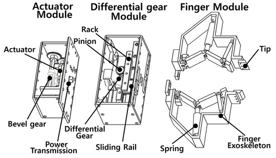
Figure 1.
Overview of the designed gripper.
The differential module converts the output axes of the differential gear into linear motion and is applied to the gripper finger slide motion. A single differential gear is used to transmit one input power to two output axes. At this time, if loads (friction, external force, etc.) act on one output axis and cause it to stop or slows down, it has a gear train whose rotation amount of the opposite output axis is automatically adjusted. Accordingly, load adaptation using a differential gear is possible. In this paper, the gripper finger slide motion is applied by changing the differential gear’s output axes into linear motion. Load adaptiveness is possible when one of the gripper fingers is jammed on an object or a finger load is applied. Therefore, even if a load is applied to one finger by the differential gear, resulting in different movement speeds or rotation amounts, adaptation by motion is possible because the reduced movement speed and rotation amount are compensated for on the opposite side.
2.1. Differential Actuating Mechanism
Figure 2a shows the structure of the differential gear; at this time, Figure 2b shows the schematic for driving two fingers by putting one actuator in the differential mechanism. The power generated by the actuator changes the position of the power vertically through the bevel gear, and the power is connected to the input of the differential gear. As shown in Figure 2b, the differential gear consists of a ring gear and an internal bevel gear, which is the same as the gear structure commonly used in automobiles. A linear motion is produced by rack and pinion on both output axes of the differential gear.

Figure 2.
Structure of the actuator using a differential gear mechanism. (a) Structure of differential gear. (b) Schematic of whole driving mechanism. (c) Realization of actuator.
Figure 2c shows the designed combination of the differential gear module and actuator module. The parallel differential adaptive gripper proposed in this paper expands the scalability of the gripper in the form of a module.
Figure 3a shows the adaptive function of load added through differential gear. It shows that grasping is possible due to mutual compensation of both fingers, even if the gripper is not positioned in the center of the gripper when grasping an object. Figure 3b shows an example of grasping that can be realized when there is un immobility constraint on one finger. In this situation, It is possible to grasp un object by moving the other unconstrained finger. This functionality may be useful when the gripping space of one side is narrow.
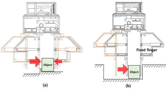
Figure 3.
Grasp modes using differential gear actuator. (a) Jammed grasp mode. (b) Fixed finger grasp mode.
2.2. Architecture of Adaptive Gripper Finger Mechanism
Figure 4 shows the structure of the gripper finger. Figure 4a shows the schematic of the finger, Figure 4b shows the structure of the gripper finger, and Figure 4c indicates the area that can be grasped.

Figure 4.
Finger structure of proposed self-adaptive gripper (a) Kinematic structure (left: neutral and right: compressed). (b) Designed structure (left: neutral and right: compressed). (c) Grasping zones by grasping methods.
The shape adaptability of the grasping is realized by the gripper’s finger structure. And basically, the gripper considers the jaw-type parallel grasping motion. As shown in Figure 4a, the proposed self-adaptive grasping can be performed by combining the exoskeleton of the finger in red line and the inner linkages. Each of them consists of 5 links, 5 rotation joints and 1 spring. , and are serially connected, and the initial posture is trying to be maintained by the spring of .
Figure 5a–c shows the proposed grasp method of the parallel type adaptive finger. In detail, Figure 5a, Figure 5b and Figure 5c, respectively, shows pinch, spread, and encompassing graspings through parallel finger movement. Therefore, the proposed gripper shows the parallel-type gripper operates linearly, and when a grasp object enters the gripper’s grasp zone (as shown in Figure 4c), it performs grasping according to each grasp mode. Figure 5a shows a pinch grasp. The finger’s internal link performs gripping with the exoskeleton supported. Figure 5b shows the spread grasp. By the exoskeleton of the finger, the parallel gripper operates to the outside and grips an object. Figure 5c represents the encompassing grasp. The inner links of the exoskeleton perform grasp according to the shape of the grasp object by organic action.
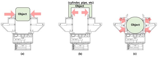
Figure 5.
Grasp modes of self-adaptive grippers. (a) Pinch grasp mode. (b) Spread grasp mode. (c) Encompassing grasp mode.
3. Analysis
3.1. Kinematic Modeling of General Differential Gear
By using the differential gear mechanism, a self-adaptive linear motion is additionally created. The differential gear completes the grasp by compensating for the speed and rotation of the other shaft even when a load on one shaft is applied. Through this, grasping is completed in the jammed situation, or grasping is completed by the other finger even when one finger is completely fixed.
Figure 6 illustrated the working principle of the differential gear mechanism. Figure 6a shows the free state as it is non-fixed, and Figure 6b shows the state where one axis is fixed. As shown in Figure 6a, the correlation between the input gear and the ring gear in the free state with no load on the differential gear is as follows.
represents the radius of the input gear and represents the rotation velocity of the input gear. represents the radius of the ring gear connected to the input gear and represents the rotation velocity of the ring gear. Therefore, the velocity of rotation of the ring gear can be obtained as follows.
In the free state, the rotation velocity and of the output axes have the same rotation velocity as the ring gear , because the internal gears do not move. is equal to the rotation velocity of the cage attached to the ring gear, so
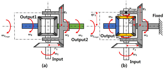
Figure 6.
Input–output relation of differential gear mechanism. (a) Single input and two outputs. (b) Single input and single output.
However, when there comes an asymmetric load between the outputs, the amount of rotation in output 2 becomes different from output 1. The relationship between the rotation of the yellow bevel gear and the rotation of the cage satisfy
Furthermore, as shown in Figure 6b, if the gray hatched bevel gear (output 2) on the right is fixed, the blue bevel gear (output 1) becomes the final output axis. Therefore, if all the radii of the bevel gears are equal, the relationship between output 1 and yellow bevel gear is
As output 2 is fixed (), Equation (4) reduces to
and the rotation velocity becomes
Therefore, by combining Equations (5) and (7), the output velocity when one finger is fixed can be expressed as follows.
3.2. Velocity Ratio of Differential Actuation
The proportion of differential velocity plays an important role in the load adaptiveness of the gripper finger. The two output rotations of the differential gear are transformed into a linear motion for each finger, creating a grasping motion; therefore, even if the velocity is reduced by the load of one fingertip, the grasping is completed by compensating the velocity by the other. In an extreme case among them, when one finger is fixed, only the other finger operates so that the load can be adjusted and the object can be grasped adaptively. Therefore, the relative velocity of the gripper fingers can be known when load adaptability occurs according to the proportion.
Figure 7 represents the velocity proportion of the two output axes of the differential gear. In detail, when there is , which defines the velocity proportion ranging from 0 to 1 and input velocity () with increasing patterns from −1 to 1, the ratio of the two output axes can be determined. Therefore, the output axes rotation velocity and share the total capacity of output velocity as shown in Figure 7.
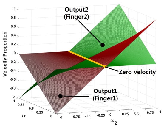
Figure 7.
Simulation of velocity ratio for the differential gear mechanism.
Inversely, if and are known, the input velocity can be obtained as
Now, if we define as
and () as a parameter, then
Finally, the input rotation velocity satisfies
In the above equations, can be considered as an unknown parameter which might be set by nature in advanced to an external load. However, it is good that the grasping by the proposed differential gear system is always fulfilled anyway whatever would be.
3.3. Kinematic Modeling of Gripper Finger
The gripper finger’s internal linkage consists of five links, five joints, and one spring. Mechanical interpretation is important in determining the position of the finger according to an external object. To help easier understanding, the kinematic model is illustrated as shown in Figure 8 according to the mechanical structure and mechanical characteristics of the proposed adaptive-finger.
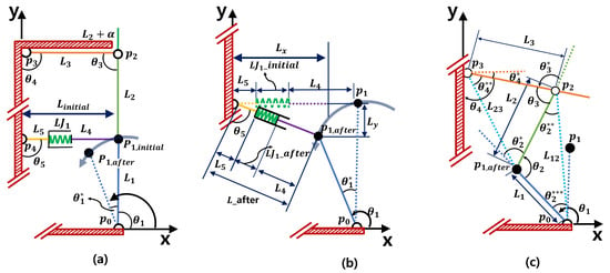
Figure 8.
Kinematic model of the proposed self-adaptive gripper. (a) Link movement (b) Links and movements. (c) Links , , and movements.
The gripper finger employs a mechanism in which the main point called entails the movements of the rest of the joints. When the angle of is defined as , and may be expressed as follows.
The position at the initial pose is defined as , which is
As shown in Figure 8a, the total length of the middle link is equal to sum of the initial length of the spring and the lengths of links 4 and 5, which could be the design variables. That is,
Suppose the gripper’s pose is changed from Figure 8a to Figure 8b. As shown in Figure 8b, , the middle link length after movement, can be determined by using and , which is related to the position before and after the movement. Thus,
and therefore, becomes
The amount of spring after movement, , can be determined by subtracting and from as
Therefore, the spring force , determined by the spring constant k and the amount of deformation, is
When the link and the middle link happen to be collinear, the spring force becomes the maximum, so does the compressed amount of the spring.
Now, let us turn to Figure 8c. In order to obtain , it is necessary to know the location of .
is defined as . Therefore, according to the second law of cosines, is determined as follows.
Therefore, and can also be determined by the sine law.
Once we determine , then is also known, so is the position .
Concerning position , it is invariant through the pose. Thus, from Figure 8a, the position can be written as
Since we know the vertex positions of , the angles and can be obtained as follows.
For , it is calculated using and as follows.
And can be simply obtained by
Therefore, it became possible to know all the joints according to the movement of through kinematic analysis. Additionally, the reaction force of the spring according to the position of each point was calculated.
3.4. Contact Force of Screw Theory
Screw theory is a way of expressing movement and force in robots. When expressed as screw motion, the prismatic motion in the k-axis direction and the revolutionary motion in the k-axis direction are added to form a screw motion in the k-axis direction. The general form of the joint screw is as follows:
h represents the pitch of the screw, and represents only pure rotation, so the revolute joint and the prismatic joint are expressed as follows.
And the reciprocal screw is a non-zero screw that produces zero when multiplied by a screw, called a reciprocal screw. In the structure of the gripper presented above, after the actuator is provided in a linear direction, is determined according to the object and the shape of the link is changed. In the structure of the finger, each revolute joint rotates in the z-axis direction in the x-y plane, and the shape of the gripper links is determined. As the linkage is varied according to the contact pose between the linkage and the object, the contact points and configurations are shown in Figure 9.

Figure 9.
Schematic of force interaction based on screw theory. (a) Reciprocal screw in . (b) Reciprocal screw in .
Figure 9a shows the screw for the contact point of and Figure 9b shows the screw for the contact point of . For each case, the linear force of the spring is calculated using the screw of each joint according to the contact point.
Consider the twist written as
is the twist of expressed as axis coordinate, and is the speed of the leg and the joint, is the unit screw represented axis coordinate of the joint in the leg. is the sum of the degrees of freedom of all joints included in the leg in . The screw related to the first leg on are written in the following equations.
where in Figure 9a. The screw of the second leg on is as follows.
where , , in Figure 9a. And the screw of the third leg on is as follows.
where, , , in Figure 9a.
The combination of unit screws constituting each leg of (contact point of ) is shown as follows.
The screw of the first leg on is as follows.
where , in Figure 9b. Here, the screw of the second leg on is as follows.
where , , in Figure 9b. Additionally, the screw of the third leg on is as follows.
where , in Figure 9b.
Calculate the screw with respect to the normal direction force about the contact points and of and in the determined shape. Therefore, following the general Jacobian theory, the Jacobian matrix relation of the velocity for the output points and as follows.
where represents the velocity of the spring, is the product of the reciprocal screw and the active joints, represents the matrix of the reciprocal screws, all of which are written as
where is reciprocal screw.
If and are approximated as the normal direction velocity of the contact point, and only and among the six and v elements of those screws are expressed in the vector space of , then
where is the Jacobian for a-vector, , representing the contact normal directional coordinates. It is defined as
where means the contact unit vector. Therefore, combining Equations (39) and (40), we obtain
Taking the inverse of to the above, we obtain
Then we need to calculate the linear force of the spring using the virtual work principle, under the wrenches , acting in the x-y plane of the contact points. Therefore, if it is summarized in the form of , the spring force can be written finally as
where
After all, since the proposed gripper has a several number of contact points and there are countless conditions of the applied contact wrenches, the above equation works as the ultimate formula showing how much the spring should be to make static balance under all conditions.
4. Prototype and Grasping Experiments
4.1. Prototype and Hardware Setup
The gripper prototype system built by the proposed design is shown in Figure 10. The motor used for the gripper is a single brushless DC motor from Maxon (model ECXSP13M). This motor is 70 mm in length and 13 mm in diameter. An optical encoder with a resolution of 1024 pulse/rev is installed in it. An IBM-compatible PC is used to control the motor through EtherCAT real-time communication.
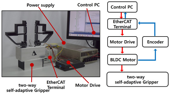
Figure 10.
Hardware setup (left) and flowchart of the gripper system (right).
Table 1 shows the hardware specifications and performance values of the prototype. With the torque of the motor being 4.3 mNm, the proposed gripper can produce a maximum grasping force of 154.2 N in accordance with the gear ratios in Table 1. Additionally, by the stall speed of 63,000 rpm of the motor, the proposed gripper allows a maximum linear speed of 200.96 mm/s. Additionally, by the design, the finger-to-finger maximum grasping stroke is 90 mm.

Table 1.
Parameter specifications of two-way self-adaptive gripper.
The size of the differential gear module is 114 × 59 × 53.2 mm, and the size of the actuator module is 93 × 59 × 41 mm. Additionally, the contact links and are 35 mm each, and the length from to for installing the spring is only 70 mm. The manufactured gripper prototype is made of aluminum and plastic material with a total weight of 690 g. particular, the gripper fingers are made of a plastic material that was 3D printed using a PLA (Poly Lactic Acid) material.
The numerical values of the grasp zones (as illustrated in Figure 4c) of the prototype is also shown in Table 1. In the case of the encompassing zone, it is a rectangular shape with a width of 90 mm, height of 70 mm, and depth of 20 mm. The zone of the pinch grasp is a rectangular shape with a width of 90 mm, height of 16 mm, and depth of 27 mm as the finger’s exoskeleton depth. The zone of the spread grasp starts in the gripper’s closed state but has the same dimension as the pinch grasp case.
Using the prototype, in this paper, a series of grasp tests were performed to verify the two-way adaptability and reliability of the proposed gripper design.
4.2. Parallel Grasping Using Differential Gear Mechanism
When using conventional grippers, the grasping of an object always occurs at the center of the gripper stroke due to the identical closing speed of the two fingers. Such grippers do not allow a fair amount of tolerance in the positioning error of the object being grasped because otherwise the grasping would become unstable. To hold and turn a door handle or to grasp a heavy body, the positioning error of the robot may also cause significant damage to the robot and the gripper as well. Such a disadvantage can be mitigated by imposing adaptability on the asymmetric loading condition on both fingertips during the linear pinch grasping.
The proposed gripper enables load adaptability in linear parallel grasping by employing the differential gear mechanism, as shown in Figure 11, where the red lines indicate the center of the gripper. Figure 11a shows the sequential steps of grasping; when one finger was held by a human hand, the grasping was completed with the other finger. Therefore, the gripper operated asymmetrically, but even if an external load was applied to one of the fingers, the object could be gripped safely by compensating for the closing action with the other finger. Figure 11b shows the returning phases of the gripper fingers back to their original position. Even if the initial gripper posture was not symmetric due to the adaptive grasping, it could manage to return to the home position on its own. Figure 11c shows the scenes when actually grasping a circular object. The left finger was intentionally held by a human hand, but the right finger completed the grasping any way. In this situation, inner links were bent according to the shape of the grasped object. This result shows the two kinds of adaptability of the gripper during the parallel encompassing grasping: the load adaptability and the shape adaptability. (More detailed demonstration of the shape adaptability shall be given in the next subsection). After all, the proposed gripper, different from the conventional grippers, did not have to complete the grasping at the center, but could deal with the external load (including jamming or one-finger-fixed situations) in an adapted manner to finish the required grasping. Therefore, the results verified that the gripper using differential gear offers adaptability in the parallel grasping motion.
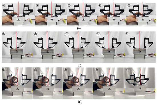
Figure 11.
Experimental tests for adaptability in the parallel grasping. (a) Jammed situation (With the left finger being fixed, the right gripper finger completes the grasp); (b) Recovery to home position (Fingers return to home position from asymmetric grasping); (c) Load and shape adaptive grasping (With the left finger being fixed, the right finger completes the encompassing grasp of a circular object of mm and weight 36 g).
4.3. Finger Shape Adaptation
The finger-shape adaptive grasping is performed by applying the three grasping methods: encompassing, pinch, and spread according to the shape of the object. In encompassing and pinching, the gripper adaptively performs grasping by passively deforming the linkage in accordance with the shape of the object’s contact surface.
Figure 12 shows the experimental results for encompassing grasping. Figure 12a shows the process of grasping a circular soda can. When the grasping was started, the soda can was placed in the encompassing grasp zone, and the gripper fingers on both sides approached in parallel to grasp the object. At this time, the internal links began to encompass the object with lateral linkage being bent passively to safely hold the can. Figure 12b shows the screenshots of holding various objects other than the circular can by the encompassing grasp. The leftmost case was holding an object that was located across the pinch grasp zone and the encompassing grasp zones. In the middle of Figure 12b, a rectangular (50.36 × 95.2 × 31.6 mm) object lying in the encompassing zone was held adaptively. The rightmost case shows grasping a tool with a weight of 166 g. In all these cases, the internal linkage became complied with the shape of the objects being grasped.
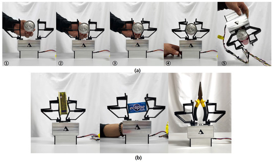
Figure 12.
Experimental tests for shape adaptability in the encompassing grasp. (a) Sequential steps of the encompassing grasp to hold an unopened soda can (Mass: 276 g, Size: mm, and length 132.6 mm); and (b) encompassing grasp to hold various objects (Leftmost object: mass 138 g with size 50.36 × 95.2 × 31.6 mm, Middle object: mass 85 g with size 39.45 × 22.93 × 75.9 mm, Rightmost object: mass 166 g).
Figure 13 shows the experimental results by using parallel pinch grasping. Figure 13a shows the sequential steps of grasping an electronic part having a flat shape. As expected, the gripper could hold the object without difficulty. Figure 13b shows the sequential step of grasping a thin plastic card lying on a desktop. Grasping a thin card is considered a difficult task by the conventional adaptive grippers due to their non-linear finger movement, whereas the proposed self-adaptive gripper can manage to pick it up. Figure 14 shows the experimental results by using the spread grasping. Note that the spread grasping is performed by driving the fingertips in the opposite direction, and therefore it is suited for holding objects with open empty holes. As shown in the experimental test, the paper cup was grasped safely by the spread grasping, which shows another possible grasping method of the proposed gripper design.
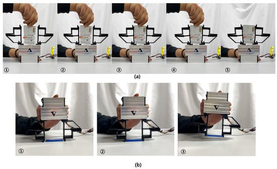
Figure 13.
Sequential steps of pinch grasp. (a) An electronic part grasping (Mass: 50 g, size: 66.4 × 98.82 × 11.75 mm). (b) A thin plastic card grasping (Mass: 4 g, size: 20 × 78.6 × 6.3 mm).

Figure 14.
Sequential steps of spread grasp to hold an empty paper cup (Mass: 20 g, size: mm with length 160 mm).
In summary, through the experimental results in this section, we verified that the two-way self-adaptive capability, i.e., the load adaptability in the parallel grasping motion and shape adaptability in the encompassing grasping using only a single actuator. In particular, due to the load adaptability, we could confirm that the grasping can be completed in the jammed situation using the differential gear mechanism, which is our notable contribution as no previous conventional self-adaptive grippers can guarantee this. We also confirmed that load and shape adaptability can be simultaneously achieved. Enabling the perfect parallel fingertip movement was additional merit for the proposed gripper, while the conventional adaptive grippers, mostly adopting the 4-bar linkage structure, do not provide perfect parallel fingertip movement. A consequent disadvantage of the conventional adaptive grippers is the significant reduction in the graspable zone during parallel grasping, whereas the proposed gripper fully uses its whole stroke distance to pick up the objects located within it.
5. Conclusions
This paper proposes a gripper that provides two-way self-adaptiveness in parallel pinch grasping and encompassing grasping by using one actuator and two mechanisms (see Supplementary Material). The adaptability for parallel grasping motion is solved by using a differential gear mechanism that can complete parallel pinch grasping even when an uneven resistive load to the two fingers is applied. In addition, it overcomes the disadvantages of the conventional gripper which fails in the perfect parallel pinch grasping due to the grasping point always being located only in the center. The adaptability to the object shape during the encompassing grasping is achieved by using a separable internal linkage around the exoskeletal outer frame. Thus, the proposed gripper provides encompassing, spread, and pinch grasp methods by using only one actuator. For the proposed gripper design, kinematic analysis of the differential gear and speed ratio of both fingers were analyzed. In addition, the force of the contact point was analyzed through the kinematics of the finger structure and the screw theory. Experimental results verified that the prototype of the proposed design of the gripper was adaptable to the loading condition during the pinch grasping. In particular, even when a gripper’s finger was prevented from motion, the other finger managed to complete the grasping. The return posture of the gripper after the pinch grasping was always reset regardless of whether the pinch grasping event was asymmetric or not, which is good for repetitive tasks. The gripper was also able to grasp objects of various shapes, including a cylinder-shaped object, rectangular objects, and an arbitrarily-shaped object adaptively during the encompassing action by passively modifying the posture of the internal linkage. Quantitatively, the prototyped gripper was able to produce a maximum force of 154.2 N, a maximum stroke of 90 mm, and a maximum speed of 200.96 mm/s by using a 30.1 W brushless DC motor. We believe the proposed two-way adaptive gripper design can contribute to many robotic grasping tasks which involve uncertainties in terms of the object shapes and task conditions, allowing a sufficient degree of adaptability in many factories and service applications.
Supplementary Materials
The following supporting information can be downloaded at: https://www.mdpi.com/article/10.3390/act12010014/s1, Video S1: Development of two-way self-adaptive gripper using differential.
Author Contributions
Conceptualization, B.K.; methodology, B.K. and J.C.; software, B.K.; validation, B.K. and J.C.; analysis, B.K. and J.C.; writing—review and editing, B.K. and J.C.; project administration, J.C. All authors have read and agreed to the published version of the manuscript.
Funding
This study was supported in part by “Regional Innovation Strategy (RIS)” through the National Research Foundation of Korea (NRF) funded by the Ministry of Education (MOE) (2021RIS-004), by the Korea Energy Technology Evaluation and Planning (KETEP) grant funded by the Ministry of Trade, Industry and Energy (MOTIE) (No. 20202020800020), and by the Korea University.
Data Availability Statement
Not applicable.
Conflicts of Interest
The authors declare no conflict of interest.
References
- Chen, F. Gripping mechanisms for industrial robots: An overview. Mech. Mach. Theory 1982, 17, 299–311. [Google Scholar] [CrossRef]
- Boubekri, N.; Chakraborty, P. A Systematic Review and Meta-analysis of Robotic Gripper. Integr. Manuf. Syst. 2002, 13, 520–531. [Google Scholar] [CrossRef]
- Long, Z.; Jiang, Q.; Shuai, T.; Wen, F.; Liang, C. Robotic grasping: Gripper designs, control methods and grasp configurations—A review of research. IOP Conf. Ser. Mater. Sci. Eng. 2020, 782, 42–55. [Google Scholar]
- Samadikhoshkho, Z.; Zareinia, K.; Janabi-Sharifi, F. A brief review on robotic grippers classifications. IEEE Can. Conf. Electr. Comput. Eng. 2019, 12, 289–299. [Google Scholar]
- Robotiq. Available online: https://robotiq.com/products (accessed on 12 November 2022).
- Shunk. Available online: https://schunk.com/ (accessed on 12 November 2022).
- Okada, T. Computer control of multijointed finger system for precise object-handling. IEEE Trans. Syst. Man, Cybern. 1982, 12, 289–299. [Google Scholar] [CrossRef]
- Jacobsen, S.; Iversen, E.; Knutti, D.; Johnson, R.; Biggers, K. Design of the Utah/MIT dextrous hand. In Proceedings of the IEEE International Conference on Robotics and Automation, San Francisco, CA, USA, 7–10 April 1986. [Google Scholar]
- Tuffield, P.; Elias, H. The shadow robot mimics human actions. Ind. Robot. Int. J. 2003, 30, 56–60. [Google Scholar] [CrossRef]
- Loucks, C.; Johnson, V.; Boissiere, P.; Starr, G.; Steele, J. Modeling and control of the stanford/JPL hand. In Proceedings of the IEEE International Conference on Robotics and Automation, Raleigh, NC, USA, 31 March 1987. [Google Scholar]
- Chen, Z.; Lii, N.Y.; Jin, M.; Fan, S.; Liu, H. Cartesian impedance control on five-finger dexterous robot hand DLR-HIT II with flexible joint. In Proceedings of the International Conference on Intelligent Robotics and Applications, Aachen, Germany, 10–12 November 2010. [Google Scholar]
- Chaigneau, D.; Arsicault, M.; Gazeau, J.P.; Zeghloul, S. LMS robotic hand grasp and manipulation planning (an isomorphic exoskeleton approach). Robotica 2008, 26, 177–188. [Google Scholar] [CrossRef]
- Bridgwater, L.B.; Ihrke, C.A.; Diftler, M.A.; Abdallah, M.E.; Radford, N.A.; Rogers, J.M.; Yayathi, S.; Askew, R.S.; Linn, D.M. The robonaut 2 hand-designed to do work with tools. In Proceedings of the IEEE International Conference on Robotics and Automation, Saint Paul, MN, USA, 28 June 2012. [Google Scholar]
- Crisman, J.D.; Kanojia, C.; Zeid, I. Graspar: A flexible, easily controllable robotic hand. IEEE Robot. Autom. Mag. 1996, 3, 32–38. [Google Scholar] [CrossRef]
- Biagiotti, L.; Melchiorri, C.; Vassura, G.W. Control of a robotic gripper for grasping objects in no-gravity conditions. In Proceedings of the IEEE International Conference on Robotics and Automation, Seoul, Republic of Korea, 21 May 2001. [Google Scholar]
- Figliolini, G.; Ceccarelli, M. A novel articulated mechanism mimicking the motion of index fingers. Robotica 2002, 20, 13–22. [Google Scholar] [CrossRef]
- Akin, D.L.; Carignan, C.R.; Foster, A.W. Development of a four-fingered dexterous robot end effector for Space operations. In Proceedings of the IEEE International Conference on Robotics and Automation, Washington, DC, USA, 11 May 2002. [Google Scholar]
- Lu, Q.; Wang, J.; Zhang, Z.; Chen, G.; Wang, H.; Rojas, N. An Underactuated Gripper based on Car Differentials for Self-Adaptive Grasping with Passive Disturbance Rejection. In Proceedings of the IEEE International Conference on Robotics and Automation, Xi’an, China, 30 May 2021. [Google Scholar]
- Tamamoto, T.; Keita, T.; Koichi, K. Development of gripper to achieve envelope grasping with underactuated mechanism using differential gear. J. Robot. Mechatronics 2018, 30, 855–862. [Google Scholar] [CrossRef]
- Birglen, L.; Laliberté, T.; Gosselin, C.M. Underactuated Robotic Hands; Springer: Berlin, Germany, 2007; Volume 40. [Google Scholar]
- Birglen, L.; Gosselin, C.M. Kinetostatic analysis of underactuated fingers. IEEE Trans. Robot. Autom. 2004, 20, 211–221. [Google Scholar] [CrossRef]
- Nassar, F.; Birglen, L. Force analysis of minimal self-adaptive fingers using variations of four-bar linkages. Mech. Sci. 2021, 12, 1037–1049. [Google Scholar] [CrossRef]
- Gao, B.; Yang, S.; Jin, H.; Hu, Y.; Yang, X.; Zhang, J. Design and analysis of underactuated robotic gripper with adaptive fingers for objects grasping tasks. In Proceedings of the IEEE International Conference on Robotics and Biomimetics, Sanya, China, 3–7 December 2016. [Google Scholar]
- Kim, Y.J.; Song, H.; Maeng, C.Y. BLT Gripper: An Adaptive Gripper with Active Transition Capability between Precise Pinch and Compliant Grasp. IEEE Robot. Autom. Lett. 2020, 5, 5518–5525. [Google Scholar] [CrossRef]
- Kang, L.; Kim, S.H.; Yi, B.J. Modeling, Design, and Implementation of an Underactuated Gripper with Capability of Grasping Thin Objects. Machines 2021, 9, 347. [Google Scholar] [CrossRef]
- Li, J.; Kong, Y.; Dong, M.; Jiao, R. Development of a linear-parallel and self-adaptive under-actuated hand compensated for the four-link and sliding base mechanism. Robotica 2022, 40, 2047–2064. [Google Scholar] [CrossRef]
- Birglen, L. Enhancing versatility and safety of industrial grippers with adaptive robotic fingers. In Proceedings of the IEEE/RSJ International Conference on Intelligent Robots and Systems, Hamburg, Germany, 28 September 2015. [Google Scholar]
- Birglen, L. Design of a partially-coupled self-adaptive robotic finger optimized for collaborative robots. Auton. Robot. 2019, 43, 523–538. [Google Scholar] [CrossRef]
- Kok, Y.Y.; Low, K.H. Design and Evaluation of an Underactuated Adaptive Finger for Parallel Grippers. In Proceedings of the 15th International Conference on Control, Automation, Robotics and Vision, Singapore, 18 November 2018. [Google Scholar]
- Kang, B.K.; Cheong, J.N.; Jung, D.W. Robot Gripper Capable of Various Task Depending on the Object to Be Grasped. Republic of Korea Patent 10-1984543, 27 May 2019. [Google Scholar]
- Kang, B.K.; Cheong, J.N.; Jung, D.W. Adaptive Robot Gripper System. PCT/KR2021/05133, 30 April 2021. [Google Scholar]
- Kang, B.K.; Cheong, J.N.; Kim, M.Y. Robot Gripper. Republic of Korea Patent 10-2449340, 27 September 2022. [Google Scholar]
Disclaimer/Publisher’s Note: The statements, opinions and data contained in all publications are solely those of the individual author(s) and contributor(s) and not of MDPI and/or the editor(s). MDPI and/or the editor(s) disclaim responsibility for any injury to people or property resulting from any ideas, methods, instructions or products referred to in the content. |
© 2022 by the authors. Licensee MDPI, Basel, Switzerland. This article is an open access article distributed under the terms and conditions of the Creative Commons Attribution (CC BY) license (https://creativecommons.org/licenses/by/4.0/).