Article

Characterization of LCR Parallel-Type Electromagnetic Shunt Damper for Superconducting Magnetic Levitation

Department of Mechanical Engineering, Faculty of Science and Technology, Keio University, 3-14-1 Hiyoshi, Kohoku-ku, Yokohama 223-8522, Japan
*
Author to whom correspondence should be addressed.
Actuators 2022, 11(8), 216; https://doi.org/10.3390/act11080216
Submission received: 16 June 2022 / Revised: 21 July 2022 / Accepted: 22 July 2022 / Published: 2 August 2022
(This article belongs to the Special Issue Advanced Technologies in Superconducting Actuators)

Abstract

:
This study investigated the effect of electromagnetic shunt dampers on the resonance amplitude reduction in a superconducting magnetic levitation system. There are two types of electromagnetic shunt dampers, series type and parallel type, depending on the configuration of the electric circuit, and their damping characteristics may differ depending on the external resistance value in the circuit. In this study, after discussing the vibration-suppression effects of both types according to the governing equations, vibration experiments were conducted using both dampers with different resistance values. As a result, it was confirmed that, for the larger resistance value, the amplitude reduction effect is smaller in the series-type damper, while it remained high in the parallel type. We also performed numerical integrations, including the nonlinearity of magnetic force in the superconducting magnetic levitation system. As a result, it was numerically confirmed that the parallel-type damper can also be expected to reduce amplitude at a resonance caused by nonlinearity.

1. Introduction

The superconducting magnetic levitation system, which consists of a superconductor and permanent magnets, is capable of stable levitation without control [1,2,3]. Therefore, compared to levitation systems that require a control system, there are possible advantages, such as the simplification of the system and improvement in maintainability. It is also characterized by a high energy efficiency due to non-contact. Taking advantage of these features, it is expected to be applied to formation flight in space and flywheel systems for power storage [4,5]. However, since the damping is small in this non-contact system, the levitated body can vibrate greatly due to disturbance. Further, since the electromagnetic force generated from the superconductor is nonlinear, complicated vibration can occur [6,7,8,9,10,11,12,13]. Therefore, when developing these applications, it is important to study methods of suppressing vibration [14].
An electromagnetic shunt damper is a promising method of suppressing the vibration of the levitated body by converting the vibration energy of the target into the electrical energy of an electric circuit [15]. Since this damper can work without contact, it is suitable for non-contact superconducting magnetic levitation systems [16]. Moreover, this damper is a kind of dynamic absorber that does not require control, making it suitable for superconducting magnetic levitation systems that do not require control. Its electric circuit consists of a coil, capacitors, and resistors. There are two types of electromagnetic shunt damper, series type and parallel type, depending on how the electrical elements are assembled [17,18].
In our previous study [18], it was confirmed by numerical calculations and experiments that, when a series-type electromagnetic shunt damper is applied to the superconducting magnetic levitation system, the optimum resistance value is minute and even a small deviation of the resistance from its optimum value reduces the vibration damping effect. However, it was also confirmed by numerical calculations that the damping effect is maintained even for a larger resistance value in the case of parallel-type shunt dampers. The latter finding has not yet been experimentally verified.
Therefore, this study experimentally verified whether the parallel-type electromagnetic shunt damper could reduce the primary resonance amplitude of the superconducting magnetic levitation system, while discussing the results and comparing them with those of the series type in terms of their vibration reduction effects. It also numerically investigated the effectiveness of those two types of dampers in reducing the amplitude of nonlinear resonance caused by nonlinearity in the magnetic force.

2. Theoretical Studies

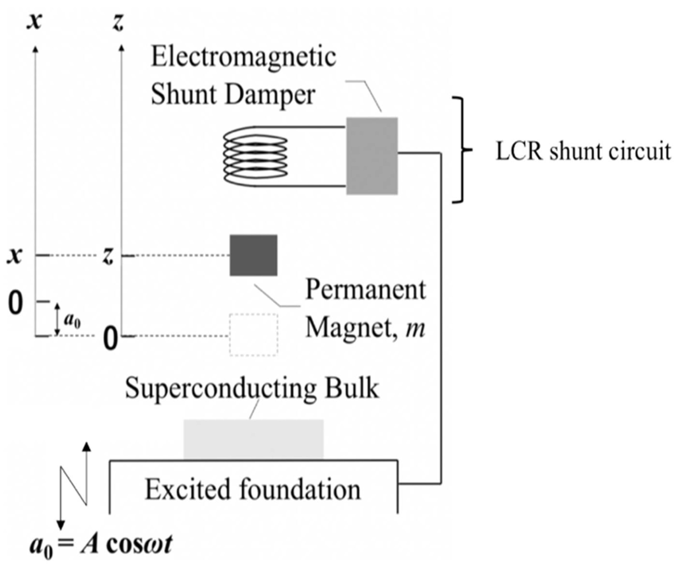
2.1. Modeling, Mechanism, and Governing Equations

Figure 1 shows our analysis model of a levitation system consisting of a superconductor, a permanent magnet, and an electromagnetic shunt damper. The system is subjected to periodic vertical vibrations of a0 = Acosωt on a shaking table, where A and w are the amplitude and the angular frequency of excitation, respectively. As the superconductor is cooled with liquid nitrogen, the magnet is held at a height z0 from the surface of the superconductor, and the magnet, after being released, is balanced with its own weight at the initial levitation height zst. Let z be the vertical displacement of the magnet from that initial levitation position, and x be its relative displacement, as seen from the shaking table. k1 denotes the spring constant obtained from a linear approximation of the electromagnetic force acting on the magnet. The mass and the magnetic moment of the magnet are denoted by m and Mm, respectively, and the magnetic permeability of the vacuum is denoted by μ0. ϕ is an important parameter in this study, denoting the electromechanical coupling coefficient between the magnet and the electric circuit of the shunt damper. Figure 2 shows two types of LCR shunt circuits, series and parallel. i denotes the current flowing in the circuit; Vemf is the electromotive force induced in the coil. L, RL, and C denote the inductance of the coil, the internal resistance, and the electric capacity of the capacitor, respectively. The external resistance is denoted by R0. In the optimum design of these circuit constants, the existence of this external resistance cannot be ignored in an actual system and can have a great influence.
The mechanism for suppressing vibration with a shunt damper is as follows. First, the electromotive force is induced in the coil by the time change in the magnetic flux penetrating through the coil due to the vibration of the magnet and the current flows in the circuit. As a result, the external magnetic field generated by the coil current causes the magnet to receive a force that suppresses its vibration, and its amplitude decreases.
The variables of time t, displacement x, and current i are nondimensionalized below by (m/k1)1/2, A, and A(k1/L)1/2, respectively. The dimensionless governing equations for x and the current i can be written as follows for the series-type and parallel-type dampers [6].
d 2 x d t 2 + 2 γ x d x d t + 3 M m 2 2 π μ 0 k 1 A 5 { 1 16 ( x + z s t / A ) 4 1 ( x + z s t / A + z 0 / A ) 4 } m g k 1 A + ψ i = ν 2 cos ν t
d 2 i d t 2 + 2 γ i d i d t + λ 2 i ψ d 2 x d t 2 = 0                                                                                     for   series   type
d 2 i d t 2 + 2 ( γ 0 + β 2 λ 2 γ 1 ) d i d t + ( 1 + β 2 ) λ 2 i = ψ d 2 x d t 2 + α β 2 λ 2 ψ d x d t                 for   parallel   type
where dimensionless parameters are given as
v = ω / k 1 / m ,   γ x = c M / 2 m k 1 ,   γ i = R m / k 1 / 2 L , γ 0 = R L m / k 1 / 2 L ,   γ 1 = L k 1 / m / 2 R L , α = L k 1 / m / R L ,   β = R L / R o , λ = m / L C k 1 ,   ψ = ϕ / k 1 L .
where c M denotes the coefficient of magnetic damping. It should be noted that the motion of the magnet and the current are coupled through the term including the dimensionless coupling coefficient ψ . The current in the series-type circuit is coupled with the acceleration of the magnet, while the current in the parallel-type circuit is coupled with the velocity as well as the acceleration of the magnet. ν denotes the nondimensional excitation frequency.

2.2. Numerical Integrations

The dynamical behaviors of the magnet under vertical excitation and the current flowing in the shunt circuit were investigated by numerically integrating (1) and (2) for the series type and (1) and (3) for the parallel type, using the 4th-order Runge–Kutta method. The parameters used in the numerical calculation correspond to the parameters used in the experiment. As reported previously [17,18], it was numerically confirmed that the parallel type also has the same damping effect as the series type.
In this study, we further examined the dependence of the damping effect of the two types of dampers on the external resistance value. Figure 3 shows the relationship between the external resistance value and the maximum amplitude of the magnet. It can be found that as the external resistance value increases, the damping effect of the series type decreases, while the damping effect of the parallel type is robustly maintained. This tendency does not change even if R o = 10 Ω or much greater. In the case of the parallel type, the dimensionless amplitude remains almost unchanged at about 2, while in the case of the series type, it continues to gradually increase, reaching a dimensionless amplitude of about 10 at 100 Ω. As the resistance further increases, it tends to approach a value of just under 12 without the damper.

2.3. Some Discussions

In general, the fixed-point theory is often used in the design of dynamic absorbers to optimally adjust the stiffness and damping coefficient parameters. This theory uses two fixed points on the frequency response curve that are independent of these parameters to find the optimal values of the parameters and suppress the amplitude in the frequency band near the resonance point of the main system. It consists of two conditions: the optimal tuning condition and the optimal damping condition. The optimum tuning condition provides the natural frequency of the subsystem so that the amplitudes of the two fixed points of the frequency response curve are the same. The optimum damping condition is the one that provides a resistance value such that the amplitude is the maximum at the fixed point. Since these two fixed points also exist in the case of a series-type shunt damper, the circuit parameters can be selected using this theory. According to this result, when applied to the superconducting magnetic levitation system in our laboratory, the optimal external resistance is a small value of sub ohms [16,18]. In reality, it is quite difficult to achieve this condition at this optimum value, considering the internal resistance of the circuit and the increase in resistance due to the heat generated during use. Figure 3, shown earlier, illustrates the change in the amplitude reduction effect when the resistance value is higher than the optimal value. In the case of the series type, this effect is sensitive to the resistance value, resulting in a decrease in damping performance as the resistance value increases.
Considering only the circuit system without the levitation system, a larger circuit resistance value results in a greater dissipation of electrical energy, leading to the suppression of electrical vibration. On the other hand, to suppress the vibration of the levitation system, a sufficient current must flow through the coil of the circuit system to produce a large electromagnetic force acting on the levitation magnet and, from this perspective, the smaller the electrical resistance, the better. Considering the equations, the last term, ψ i , on the left-hand side in the equation of motion in Equation (1) represents the electromagnetic force acting on the levitation magnet due to the coil current, and this force suppresses the vibration of the magnet. On the other hand, the last term ψ x ¨ on the left-hand side of the circuit equation for a series-type shunt damper in Equation (2) corresponds to the periodic fluctuations in the induced voltage caused by the time variation in the coil flux due to the oscillation of the levitation magnet, and the current oscillation caused by this voltage fluctuation is attenuated by the second term on the left-hand side, corresponding to the voltage drop across the resistance. The coefficient γ i in this second term is a dimensionless parameter that is proportional to the resistance, which is the sum of the external resistance and the internal resistance of the circuit. Therefore, if the resistance is too large, the current amplitude in Equation (2) will be small. Thus, the electromagnetic force term in Equation (1) will also be small, lowering the damping effect. Furthermore, if the goal is to balance the vibration-suppression effect in a certain frequency band, as per the guidelines for optimal design based on the fixed-point theory, an appropriate resistance value should be set for the system as a whole. However, in the case of series-type shunt dampers, the tolerance for deviation from the optimum value of the resistance is quite small.
On the other hand, in the case of the parallel-type shunt damper shown in Figure 2, even if the external resistance is so large that the current flowing through it is small, the magnitude of the displacement current flowing through the capacitor connected in parallel with the resistance is maintained without a decrease. Thus, unlike the series type, the magnitude of the current flowing through the coil is also maintained without decreasing for large external resistance, leading to there being no reduction in vibration suppression. The larger selectable range of the external resistance, R o , is considered advantageous for the parallel type in terms of vibration-suppression design.

3. Experimental Verification of Primary Resonance Suppression

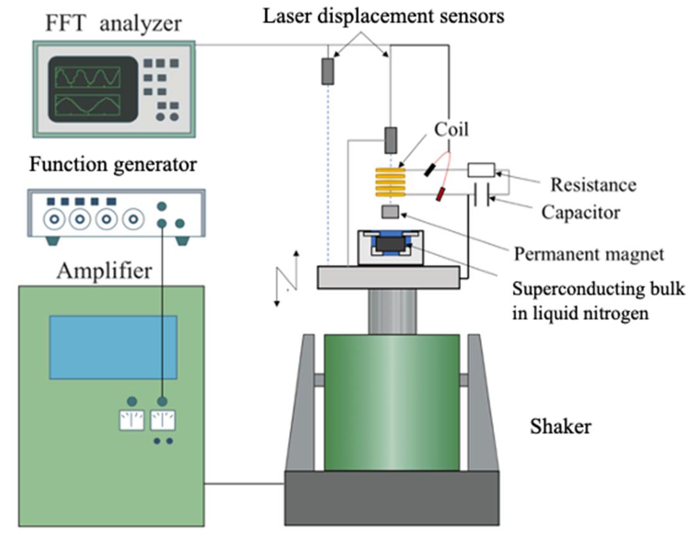
3.1. Experimental Setup and Measurement Method

Figure 4 shows a schematic diagram of the experimental setup. An Nd-based, cylindrical permanent magnet with a mass of 33.5 g, a diameter of 19.0 mm and a height of 14.0 mm was stably levitated above a GdBCO-type cylindrical superconducting bulk material with a diameter of 67.4 mm and a height of 15.6 mm after field-cooling. The initial levitation height was 9.45 mm from the surface of the superconductor. The shaking table was operated at various frequencies to vertically vibrate the superconducting bulk, resulting in the vibration of the magnet. The damper coil consisted of 234 turns of 1.4-mm diameter wire, with an inner diameter of 25.0 mm, an outer diameter of 55.0 mm, and a height of 26.0 mm. Its inductance was 1.50 mH and its resistance was 0.50 Ω. The capacitance of the capacitor was 20.8 mF. Two values, 0.15 Ω and 99.4 Ω, were used as the external resistance. In order to check whether the vibration suppression was achieved, the value of 0.15 Ω was adopted as the value obtained by the optimization based on the fixed-point theory described in Section 2.3, when a series-type electromagnetic shunt damper was used. Furthermore, in order to verify whether the amplitude reduction effect was maintained, unlike the series type, compared to deviations from that value, the value of 99.4 Ω was adopted as an extreme value at which both types of differences in the effect described in Section 2.2 are likely to appear in experiments. The parameter values of the experiment are listed in Table 1.
The displacements of the magnet and the base were measured with laser displacement meters. The current flowing through the circuit was evaluated by measuring the voltage across the coil.

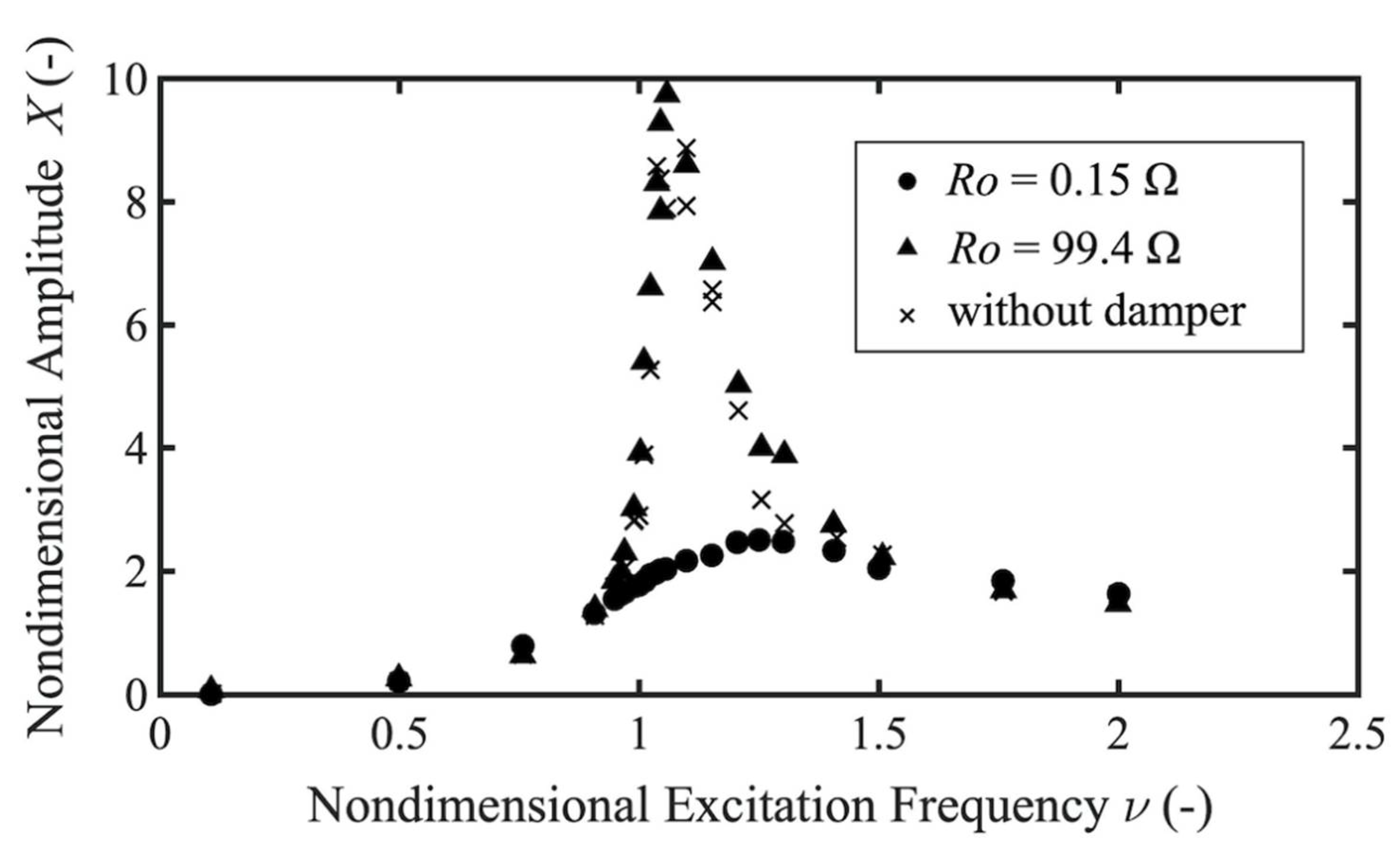
3.2. Experimental Results

Figure 5 and Figure 6 show the dimensionless frequency responses of the amplitude of the magnet obtained in the experiment with the series-type and parallel-type dampers, respectively. They plot the amplitude of the vibration component at excitation frequency. Each figure shows a comparison of the results obtained when the external resistance is Ro = 0.15 Ω and Ro = 99.4 Ω and when there is no damper. According to Figure 5, the reduction rate of the maximum amplitude with the use of the series-type damper compared to that without the damper is 74.3% with Ro = 0.15 Ω, but the amplitude does not decrease with Ro = 99.4 Ω. On the other hand, Figure 6 shows that the reduction rate of the maximum amplitude with the use of the parallel-type damper is 69.6% with Ro = 0.15 Ω, and 80% even with Ro = 99.4 Ω.

4. Numerical Prediction of Nonlinear Resonance Suppression

In the above experiments, the excitation amplitude A was 0.1 mm. We further investigated the effects of increasing the excitation amplitude by carrying out a numerical calculation with a larger excitation amplitude, A = 1.0 mm. Figure 7 and Figure 8 show the numerical results of the motion of the magnet under the series-type and parallel-type dampers with Ro = 0.15 Ω, respectively. In both figures, (a) and (b) show the time history of the motion and its frequency analysis results, respectively. There is a marked difference between the time histories of the series type shown in Figure 7a and the parallel type shown in Figure 8a. According to the frequency analysis results in (b) of both figures, the latter shows a vibration waveform with a single frequency of 1.6, which is the excitation frequency, while the former consists of two vibration components, one with an excitation frequency of 1.6 and the other with a frequency of 8, which is half of the excitation frequency of 1.6. The vibration component at one half of the excitation frequency is caused by the nonlinearity of the electromagnetic force due to superconductivity. This is a type of nonlinear resonance called a subharmonic resonance. Thus, with a larger excitation amplitude, the nonlinear resonance can be confirmed near ν = 1.6 with the series-type damper. However, these nonlinear resonances of the subharmonic component were not found with the parallel-type damper. These numerical predictions imply a possible amplitude reduction in nonlinear resonance with the parallel-type damper.
The mechanism of subharmonic resonance generation can be explained as follows, based on Equation (1). The electromagnetic force acting from the superconductor to the is levitation magnet, described by the third term on the left side of Equation (1), has a nonlinear term of the second order of the magnet displacement x . This displacement generally has a vibration component at excitation frequency ν and a vibration component at natural frequency Ω . The second-order nonlinear term described above produces a vibration component at frequency sin ( ν Ω ) t , which is obtained by multiplying these two components, sin ν t × sin Ω t . This frequency ν Ω takes the value of the natural frequency when the excitation frequency is near twice the natural frequency component, and if this is viewed as the excitation term, resonance can occur at this time. This is a resonance at half the excitation frequency and is called subharmonic resonance. When a shunt damper is added to our original levitation system to make it a 2-DOF system, the smaller natural frequency is about 0.8 in the dimensionless value, which means that this nonlinear resonance can occur at a non-dimensional excitation frequency ν of around 1.6, which is twice that value.
Furthermore, numerical calculations were carried out when the resistance value R o was increased to investigate the damping effect of the series and parallel types on the subharmonic resonance. Figure 9 plots the maximum value of the vibration component at half the excitation frequency against an increase in resistance R o for the series and parallel types, respectively. It can be seen that, as the resistance value R o increases, the damping effect of the series type decreases for the harmonic resonance, while the damping effect of the parallel type is maintained.

5. Conclusions

This study investigated whether series-type and parallel-type electromagnetic shunt dampers can reduce the primary resonance amplitude of the superconducting magnetic levitation system. The difference in the reduction effect depending on the value of the external resistance of the circuit was discussed based on equations and experimentally verified. Furthermore, the effectiveness of those two types of dampers in reducing the amplitude of the nonlinear resonance caused by the nonlinearity of the magnetic force was also numerically investigated. The conclusions are summarized as follows.
(1)
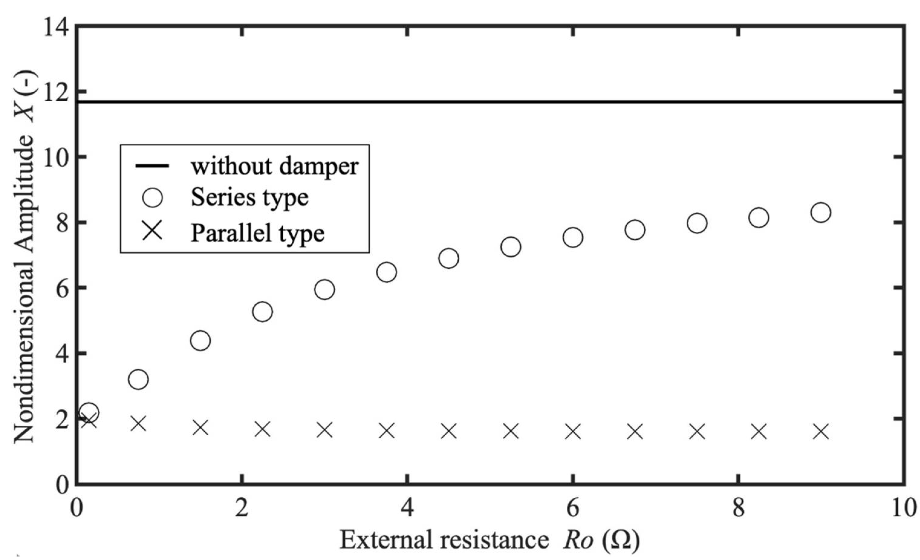
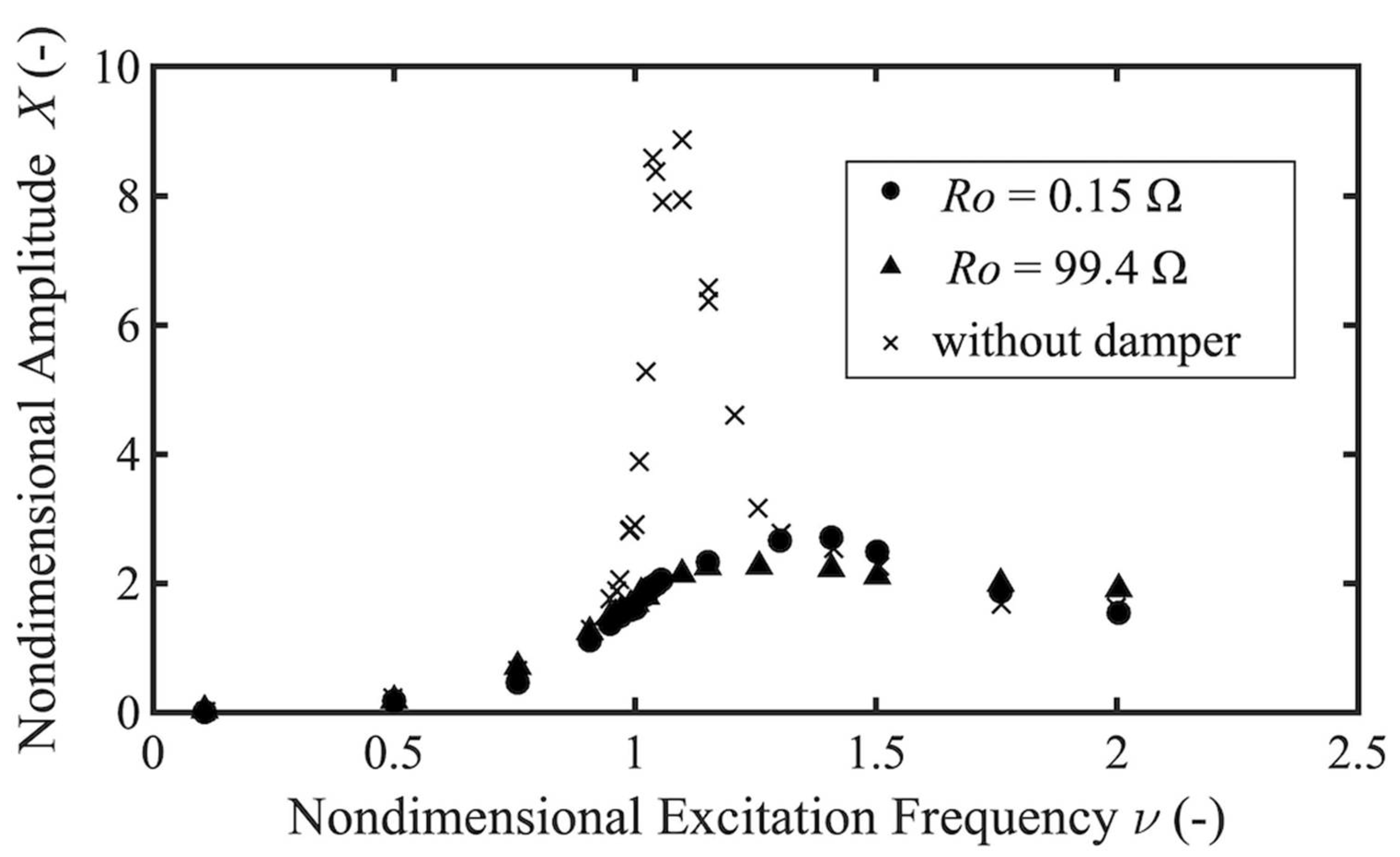
With the series-type damper, the reduction rate of the resonance amplitude reached 74.3% with an external resistance R o = 0.15 Ω, while the reduction effect was not obtained with R o = 99.4 Ω.
(2)
With the parallel-type damper, the reduction rate of the resonance amplitude reached 69.6% with an external resistance value R o = 0.15 Ω, and a reduction rate of up to 80% was obtained even with RO = 99.4 Ω. Unlike the series-type damper, the experiments confirmed that the parallel-type damper can maintain the effect of reducing the resonance amplitude even if the external resistance of the circuit is larger.
(3)
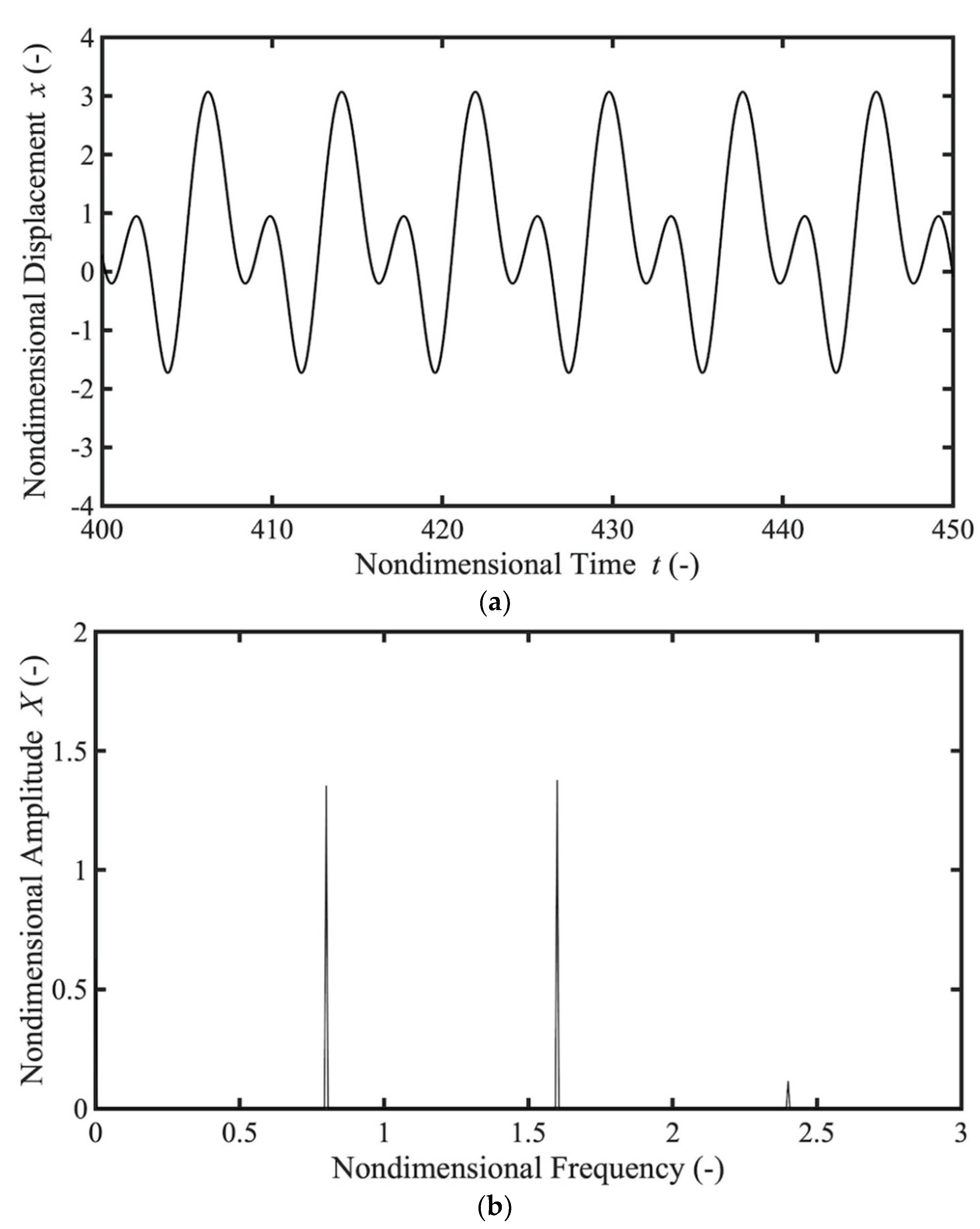
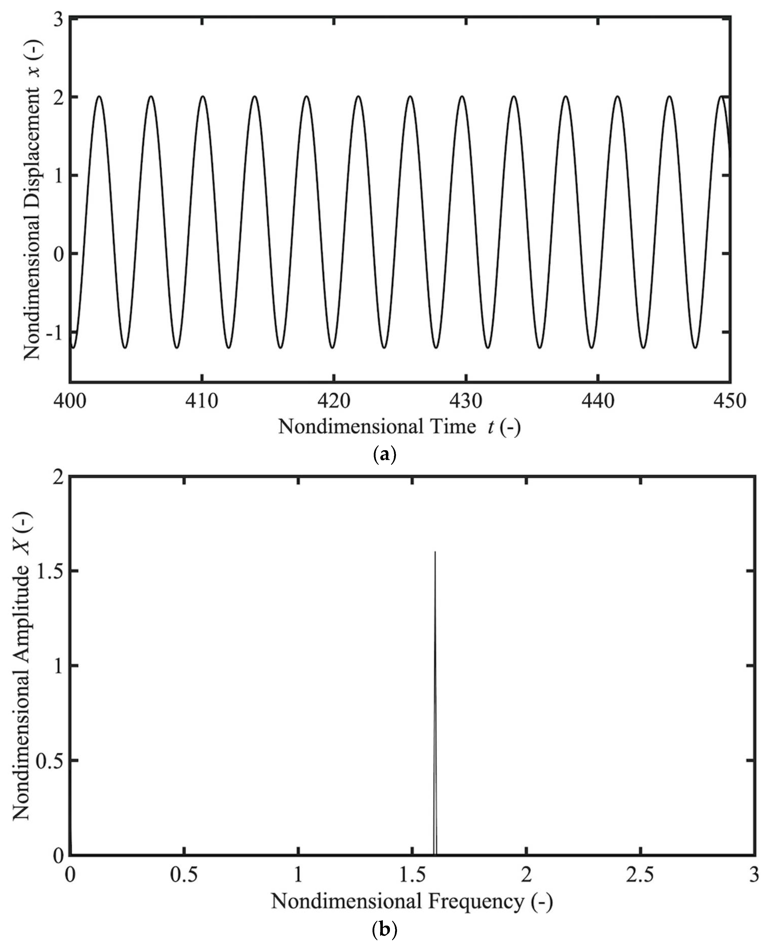
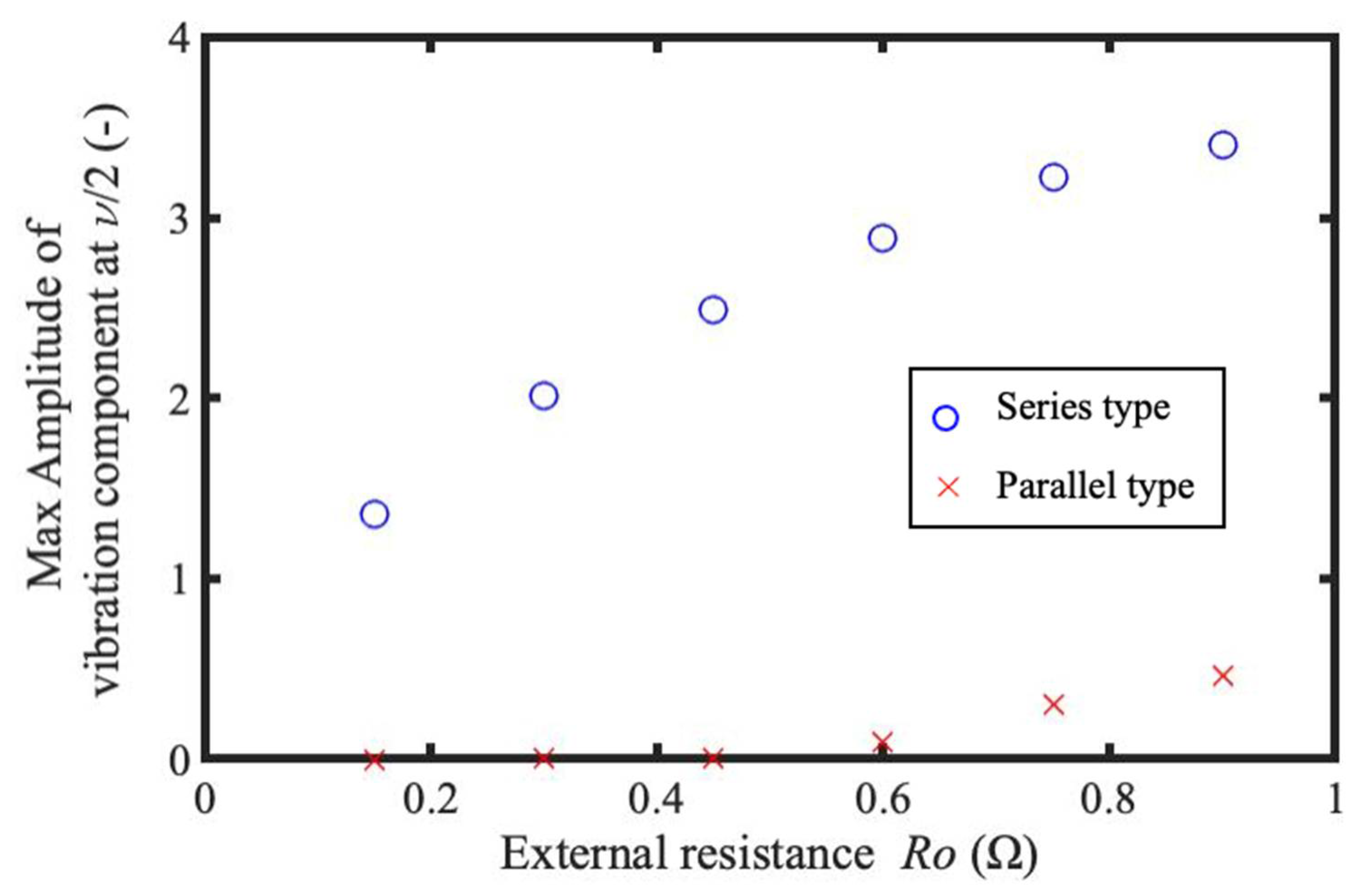
It was confirmed by numerical calculation that the parallel-type shunt damper can also be expected to reduce amplitude at resonances caused by the nonlinearity of the magnetic force. It was also confirmed by numerical calculations that the damping effect on subharmonic resonance when the external resistance R o is increased is reduced in the series type but maintained in the parallel type.
Future work will include a parameter optimization of the parallel-type shunt damper. To this end, it is necessary to find guidelines for suppressing the vibration of the mechanical system by finding the natural vibration modes of the problem, in which the velocity term contributes to the coupling of the mechanical and electrical systems. Another possible approach is the analysis of equations with frequency-dependent parameters obtained by Laplace transform. These methods are currently under investigation.

Author Contributions

Conceptualization, K.F. and T.S.; funding acquisition, T.S.; investigation, K.F. and T.S.; methodology, K.F. and T.S.; project administration, T.S.; software, K.F.; supervision, T.S.; validation, K.F. and T.S.; visualization, K.F.; writing—original draft, K.F. and T.S.; writing—review and editing, K.F. and T.S. All authors have read and agreed to the published version of the manuscript.

Funding

This work was partially supported by a 2017 grant from Tsugawa Foundation, a public interest incorporated foundation. It was established by the founder of Odawara Engineering Corporation, which provides winding equipment for motors, with his private funds to contribute to the promotion of academic research related to motors.

Acknowledgments

We thank Keisuke Uchino in our laboratory who provided insight and expertise that greatly assisted the research.

Conflicts of Interest

The authors declare no conflict of interest.

References

  1. Hull, J.R.; Murakami, M. Applications of bulk high-temperature superconductors. Proc. IEEE 2004, 92, 1705–1718. [Google Scholar] [CrossRef] [Green Version]
  2. Hull, J.R. Superconducting bearings. Supercond. Sci. Technol. 2000, 13, R1–R15. [Google Scholar] [CrossRef] [Green Version]
  3. Moon, F.C. Superconducting Levitation; Wiley-Interscience Publication: New York, NY, USA, 1994; pp. 1–30, 193–196. [Google Scholar]
  4. Shibata, T.; Sakai, S. Passive micro vibration isolator utilizing flux pinning effect for satellites. J. Phys. Conf. Ser. 2016, 744, 012009. [Google Scholar] [CrossRef] [Green Version]
  5. Bornemann, H.J.; Sander, M. Conceptual system design of a 5 MWh/100 MW superconducting flywheel energy storage plant for power utility applications. IEEE Trans. Appl. Supercond. 1997, 7, 398–401. [Google Scholar] [CrossRef]
  6. Sugiura, T.; Ogawa, S.; Ura, H. Nonlinear oscillation of a rigid body over high-Tc superconductors supported by electro-magnetic forces. Phys. C Supercond. Its Appl. 2005, 426, 783–788. [Google Scholar] [CrossRef]
  7. Shimizu, T.; Sugiura, T.; Ogawa, S. Parametrically excited motion of a levitated rigid bar over high-Tc superconducting bulks. Phys. C Supercond. Its Appl. 2006, 445, 1109–1114. [Google Scholar] [CrossRef]
  8. Sasaki, M.; Takabayashi, T.; Sugiura, T. Transition between nonlinear oscillations of an elastic body levitated above high-Tc superconducting bulks. IEEE Trans. Appl. Supercond. 2013, 23, 3600604. [Google Scholar] [CrossRef]
  9. Nayfeh, A.H.; Mook, D.T. Nonlinear Oscillations; Wiley-Interscience Publication: New York, NY, USA, 1995; pp. 20–28, 195–203. [Google Scholar]
  10. Deng, Z.; Wang, L.; Li, H.; Li, J.; Wang, H.; Yu, J. Dynamic studies of the HTS maglev transit system. IEEE Trans. Appl. Supercond. 2021, 31, 3600805. [Google Scholar] [CrossRef]
  11. Li, J.; Li, H.; Zheng, J.; Zheng, B.; Huang, H.; Deng, Z. Nonlinear vibration behaviors of high-Tc superconducting bulks in an applied permanent magnetic array field. J. Appl. Phys. 2017, 121, 243901. [Google Scholar] [CrossRef]
  12. Li, J.; Deng, Z.; Xia, C.; Gou, Y.; Wang, C.; Zheng, J. Subharmonic resonance in magnetic levitation of the high-temperature superconducting bulks YBa2Cu3O7-X under harmonic excitation. IEEE Trans. Appl. Supercond. 2019, 29, 3600908. [Google Scholar]
  13. Lin, D.; Zhao, L.; Zhou, D.; Cheng, C.; Zhang, Y.; Zhao, Y. Dynamic characteristics of levitated YBCO bulk running above the permanent magnet guideway with fluctuating magnetic field. IEEE Trans. Appl. Supercond. 2020, 30, 3603808. [Google Scholar] [CrossRef]
  14. Fujita, K.; Sugiura, T. Simultaneous suppression of translational and tilt vibrations in a superconducting magnetic levitation system by a gyroscopic damper. IEEE Trans. Appl. Supercond. 2022, 32, 3601904. [Google Scholar] [CrossRef]
  15. Inoue, T.; Ishida, Y.; Sumi, M. Vibration suppression using electromagnetic resonant shunt damper. J. Vib. Acoust. 2008, 130, 041003. [Google Scholar] [CrossRef]
  16. Uchino, K.; Sugiura, T. Experimental study on oscillation amplitude reduction of a superconducting levitation system by an electromagnetic shunt damper. IEEE Trans. Appl. Supercond. 2019, 29, 3602704. [Google Scholar] [CrossRef]
  17. Cheng, T.H.; Xuan, D.J.; Li, Z.Z.; Shen, Y.D. Vibration control using shunted electromagnetic transducer. Appl. Mech. Mater. 2010, 26–28, 905–908. [Google Scholar] [CrossRef]
  18. Fujita, K.; Uchino, K.; Ochiai, K.; Sugiura, T. Numerical analysis of amplitude reduction using electromagnetic shunt damper with an LCR parallel circuit in a superconducting magnetic levitation system. J. AEM Soc. Jpn. 2020, 28, 231–238. (In Japanese) [Google Scholar] [CrossRef]
Figure 1. Analytical model of superconducting levitation system with an electromagnetic shunt damper.
Actuators 11 00216 g001
Figure 2. Two types of LCR shunt circuit. (a) series type; (b) parallel type.
Actuators 11 00216 g002
Figure 3. Numerical result of relationship between nondimensional maximum amplitude X and external resistance value R o , obtained with each of the series-type and parallel-type dampers and without damper.
Actuators 11 00216 g003
Figure 4. Schematic diagram of the experimental setup.
Actuators 11 00216 g004
Figure 5. Frequency response plots of the vibration amplitude of the permanent magnet obtained by experiments with the series type shunt damper.
Actuators 11 00216 g005
Figure 6. Frequency response plots of the vibration amplitude of the permanent magnet obtained by experiments with the parallel-type shunt damper.
Actuators 11 00216 g006
Figure 7. Numerical results of the motion of the magnet above the superconductor excited with the amplitude A = 1.0 mm and frequency ν = 1.6 using the series-type shunt damper, showing subharmonic resonance. (a) Time history; (b) FFT.
Actuators 11 00216 g007
Figure 8. Numerical results of the motion of the magnet above the superconductor excited with the amplitude A = 1.0 mm and frequency ν = 1.6 using the parallel-type shunt damper, showing no subharmonic resonance. (a) Time history; (b) FFT.
Actuators 11 00216 g008
Figure 9. Numerical result of the relationship between maximum amplitude of the vibration component at half the excitation frequency and external resistance value Ro obtained with each of the series-type and parallel-type dampers.
Actuators 11 00216 g009
Table 1. Parameter values used in experiments.
m [kg] c M   [N·s/m] M m   [Wb·m] A [mm]
0.03350.423 1.01 × 10 6 0.1
z 0 [mm] z s t [mm] L [H] R L   [ Ω ]
10.0 9.45 1.50 × 10 3 0.500
C [mF] μ 0 [H/m] ϕ   [V·s/m]
20.8 1.26 × 10 6 1.18
Publisher’s Note: MDPI stays neutral with regard to jurisdictional claims in published maps and institutional affiliations.

