Article

Suspension-Type of Flywheel Energy Storage System Using High Tc Superconducting Magnetic Bearing (SMB)

Department of Electrical and Electronic Engineering, Kyushu Institute of Technology, 1-1 Sensui, Tobata, Kitakyushu 804-8550, Fukuoka, Japan
*
Author to whom correspondence should be addressed.
Actuators 2022, 11(8), 215; https://doi.org/10.3390/act11080215
Submission received: 19 June 2022 / Revised: 17 July 2022 / Accepted: 23 July 2022 / Published: 1 August 2022
(This article belongs to the Special Issue Advanced Technologies in Superconducting Actuators)

Abstract

:
In this paper, a new superconducting flywheel energy storage system is proposed, whose concept is different from other systems. The superconducting flywheel energy storage system is composed of a radial-type superconducting magnetic bearing (SMB), an induction motor, and some positioning actuators. The SMB is composed of a superconducting stator and a flywheel rotor. The flywheel rotor is suspended by the superconducting stator, whose one end is fixed to a stable and heavy base. Free-run experiments in the case of the unfixed stator are performed. The natural rotation decay curve, displacement at the upper position of the rotor and displacement at a lower position of the rotor are measured. Moreover, free-run experiments in the case of the fixed stator are performed, and the same dynamic characteristics of the unfixed stator are measured. Especially, impulse responses for the rotor in the case of an unfixed stator are very different from those in the case of a fixed stator. The experimental results discuss some important characteristics of the superconducting flywheel energy storage system, whose rotor is suspended by the superconducting stator.

1. Introduction

High critical temperature superconductors (HTSs) with strong pinning forces are useful for such applications [1,2,3,4]. Superconducting magnetic bearings (SMBs) are very promising as HTS applications. From a structural point of view, there are two types of SMBs, such as the radial-type SMBs and axial-type SMBs. In general, axial-type SMBs have a larger load capacity than the radial-type SMBs, because it is easy for the axial-type SMBs to make larger structures.
The flywheel energy storage system is very promising as an energy-saving system. This is because the system is very simple and is characterized by high energy density compared with other energy storage systems. Hull et al. [5] proposed a superconducting flywheel energy storage system. The flywheel measured 132 kg in weight and 245 mm in diameter. The flywheel is not so large, but the system is characterized by the axial-type SMB using a cryo-cooler. Werfel et al. [6] proposed a radial-type SMB for a superconducting flywheel energy storage system composed of a permanent magnet rotor with a diameter of ϕ 200 mm, an air gap of 3.0 mm, and stiffness of 1.8 kN/mm.
A 10 kWh-class flywheel energy storage system has been developed in Japan [7]. After that, Nagashima et al. [8] reported a superconducting flywheel energy storage system with an HTS rotor at the bottom end and a superconducting coil. The flywheel rotor measures 4000 kg and 2000 mm in diameter. The flywheel stores energy of 100 kWh at a speed of 6000 rpm. The system is now installed in a test plant in Kofu city, Yamanashi prefecture, Japan. From the results, it was found that the test was continued and was successful according to [9]. These superconducting flywheel energy storage systems comprise SMBs with an energy storage flywheel rotor and a stator with high Tc superconductors. In the case of a superconducting flywheel energy storage system with SMBs, the axial position changes to another stable position due to the flux creep phenomenon or radial active magnetic bearings (AMBs), which are added to suppress the rotor vibrations because of the weak stiffness of SMBs. Then, a new superconducting energy storage flywheel system is proposed, whose concept is different from other systems. The flywheel rotor of the new superconducting energy storage system is suspended by a superconducting stator of SMB. In addition, to investigate the difference between this superconducting energy storage system and other flywheel energy storage systems, the dynamic characteristics of the system, such as the impulse responses and free-run experiments, are studied.

2. Superconducting Flywheel Energy Storage System

The schematic illustration of the proposed superconducting flywheel energy storage system is shown in Figure 1. The superconducting flywheel energy storage system comprises an SMB with a superconducting stator and flywheel rotor, an induction motor, and some positioning actuators. Thus, the radial-type SMB is composed of the superconducting stator and the flywheel rotor. The flywheel rotor is suspended by a stator whose top end is fixed to a stable and heavy base. The superconducting stator measures 126.8 mm in diameter and 460 mm in length. The flywheel rotor and stator are set in a vacuum chamber. For the cooling down of the superconductors in the stator, liquid nitrogen flows into the superconducting stator from the top of the system.
Figure 2 shows the superconducting stator representing (a) an overview photo of the stator and (b) the structure of the superconducting stator. The lower half of the photo in Figure 2a shows the stainless chamber, and some stainless pipes in the upper half of the photo are inlets and outlets for the liquid nitrogen. The stator has doughnut-shaped superconductors (outer diameter (OD) 123.2 mm × inner diameter (ID) 93.2 mm × thickness (T) 60 mm) inside the stator, as shown in Figure 2b.
Figure 3 shows the flywheel rotor attached to the bottom end of the superconducting stator. The flywheel rotor measures OD161 mm × ID126.8 mm in diameter, 105 mm in height and 8.9 kg in weight. In the figure, the flywheel rotor is set at a gap of 0.75 mm between the flywheel rotor and the superconducting stator. Two permanent magnets (PMs) are installed on the top and bottom sides of the flywheel rotor. The flywheel rotor is connected to the induction motor (25 W) using a flexible joint. The cross-section of the flywheel rotor is shown in Figure 1.
Figure 4 shows the PM installed in the flywheel rotor, representing (a) the dimensions of the PM and (b) the photo of the PM. The PM measures OD160 mm × ID126.8 mm in diameter and 13.5 mm in height. The magnetic flux density on the surface of the PM is 0.56 T. As shown in Figure 1, two PMs in Figure 4 are installed in the flywheel rotor.

3. Experimental Results and Discussions

3.1. Free-Run Experimental Results

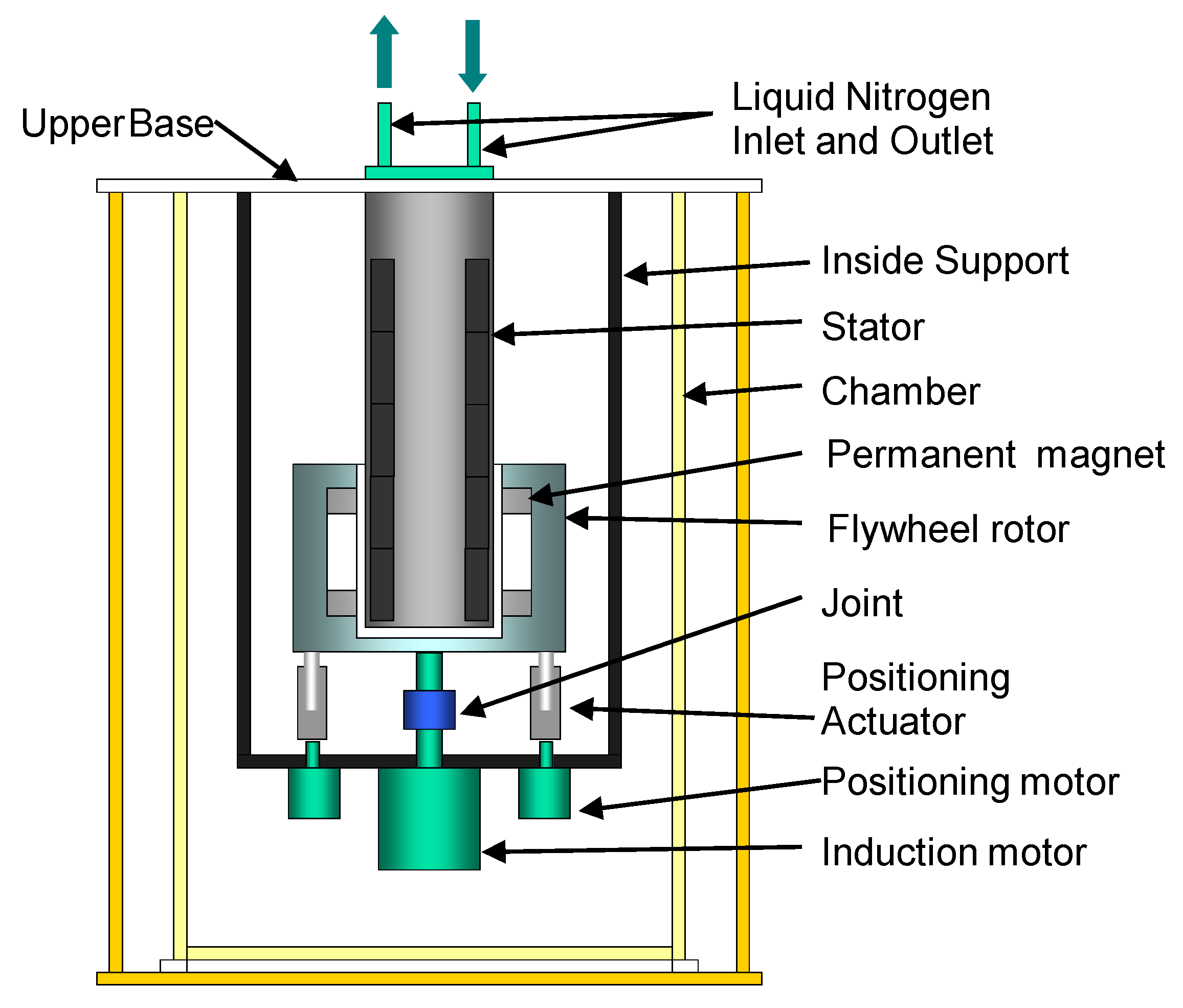
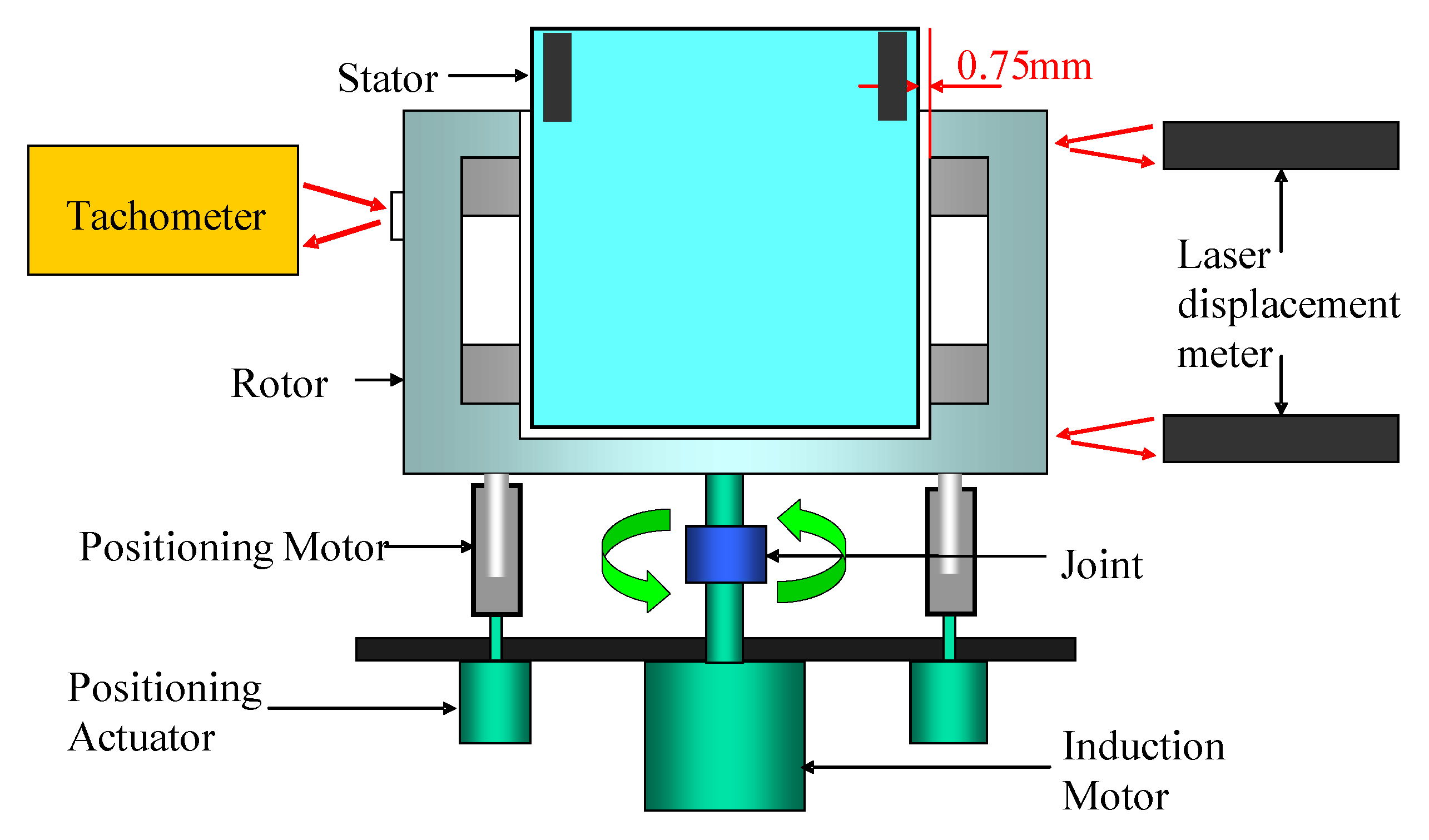
Figure 5 shows an experimental setup for a free-run experiment. The rotor is supported by four positioned linear actuators. The gap between the rotor and the stator is 0.75 mm. After field-cooling the superconductors with a gap of 0.75 mm, the actuators separate from the flywheel rotor. In this manner, the rotor can be levitated. The rotor is driven by the induction motor. The thick arrows near the joint show the rotation directions. Just after the rotation speed increases to 1000 rpm, the driving force of the motor stops. Then, the rotation speed and displacements of the rotor are measured. The displacements at the upper position of the rotor and the lower position of the rotor are measured by using two laser displacement sensors. During the experiment, the vacuum of the chamber is kept at 5 × 10⁻³ Torr using a rotary vacuum pump. The chamber vacuum 5 × 10⁻³ Torr is sufficient for the experiments performed here.
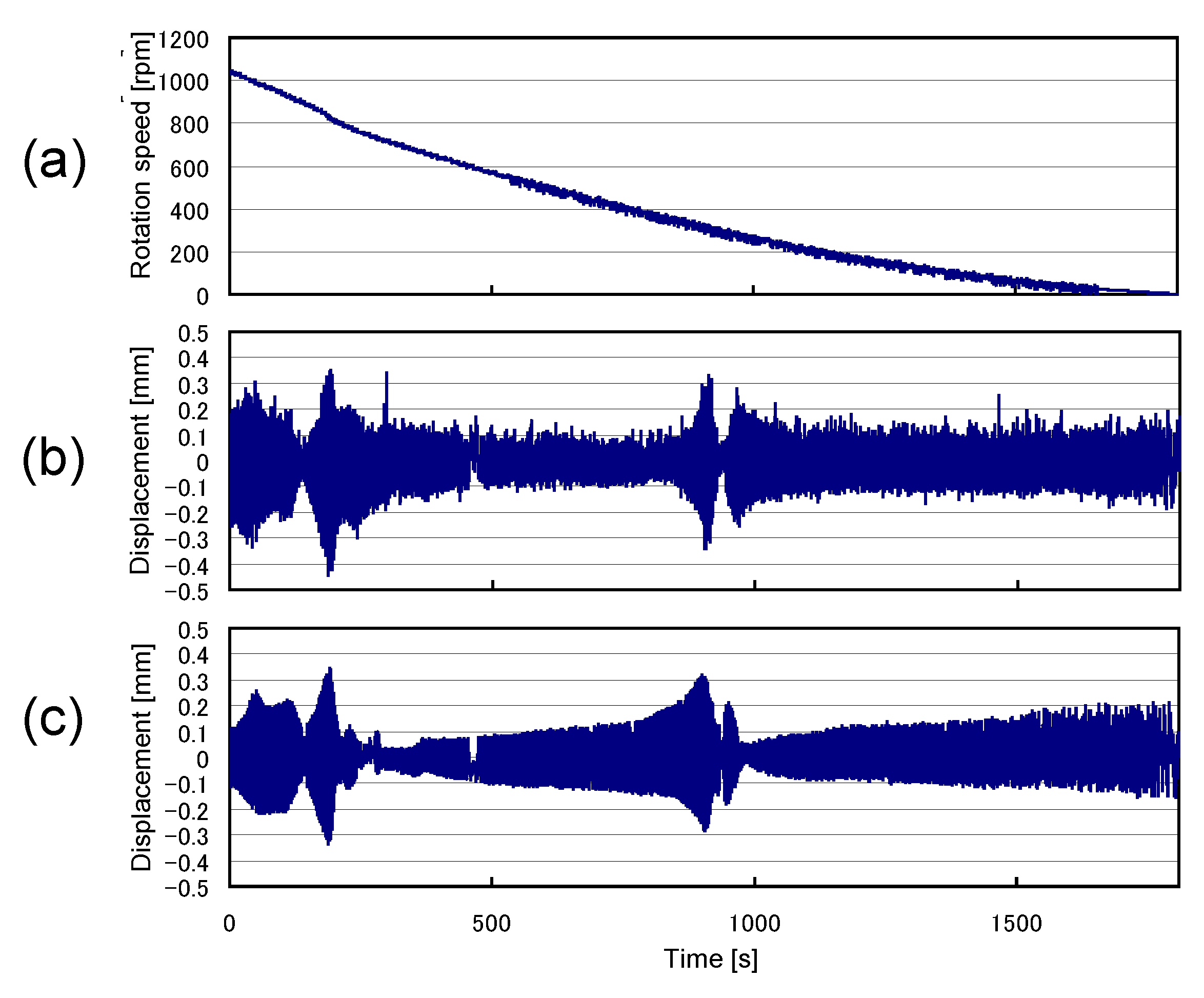
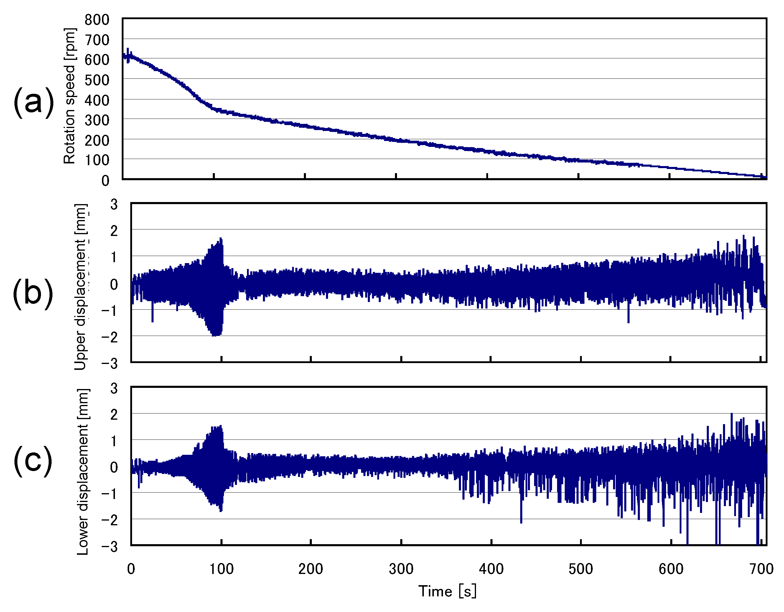
Figure 6 shows the free-run experimental results representing (a) the natural rotational decay curve, (b) displacement at an upper position of the rotor and (c) displacement at a lower position of the rotor. The rotation speed decays to zero from 1000 rpm for 1600 s. During the rotation, the displacement pattern of the upper rotor is almost the same as that of the lower rotor. There are resonance rotation speeds at 200 s and 900 s, which correspond to 800 rpm and 300 rpm, respectively. Except for these resonance rotation speeds, the displacement is less than 0.3 mm over a wide time range.
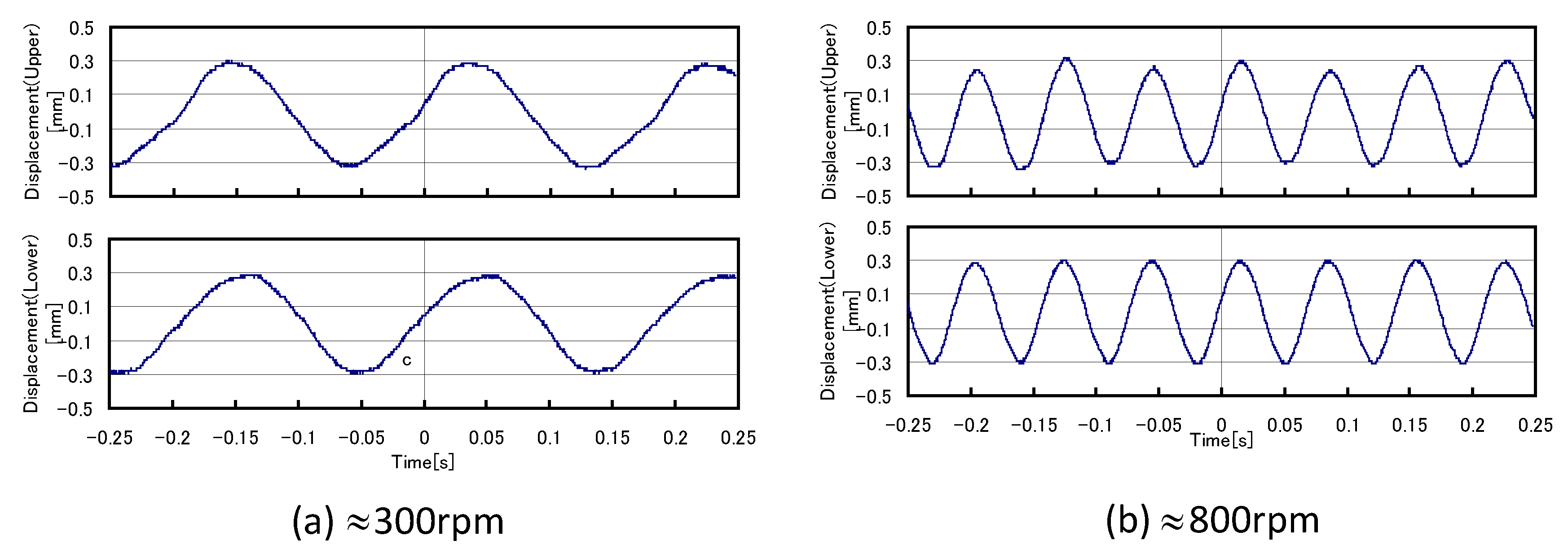
Figure 7 shows the free-run experimental results representing (a) displacements at the upper rotor (upper figure) and lower rotor (lower figure) at a speed of 300 rpm and (b) displacements at the upper rotor (upper figure) and lower rotor (lower figure) at a speed of 800 rpm. Both displacements, at the speeds of 300 rpm and 800 rpm, are less than 0.3 mmo-p. The displacement phase of the upper figure in Figure 7a is almost the same as the phase of the lower figure in Figure 7a. This means that the flywheel rotor spins in a cylindrical motion at a speed of 300 rpm. Additionally, the displacement phase of the upper figure in Figure 7b is almost the same as the phase of the lower figure in Figure 7b. This means that the flywheel rotor also spins in the cylindrical motion at a speed of 800 rpm.
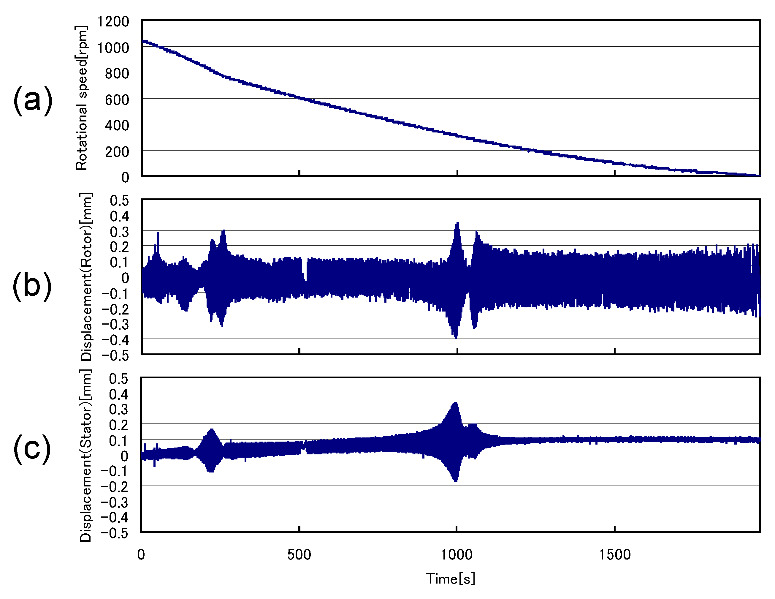
Figure 8 shows the free-run experimental results representing (a) a natural rotation decay curve, (b) displacement at the center position of the rotor and (c) displacement of the stator in just the upper position of the rotor. The rotation speed decays to zero from 1000 rpm for 1600 s. During the rotation, the displacement at the center position of the rotor is almost the same as those in Figure 6a,b. Since the flywheel rotor has a cylindrical motion, the displacement at the center position of the rotor in Figure 8b is almost the same as those in Figure 7b. Figure 8c shows that over a wide time range, the displacement of the stator in just the rotor’s upper position is less than 0.1 mm, except for the resonance rotation speeds, which are much smaller than that of the flywheel rotor in Figure 8b. However, there are some displacement peaks at 250 s and 950 s. These peaks correspond to the resonance frequencies of the flywheel energy storage system.
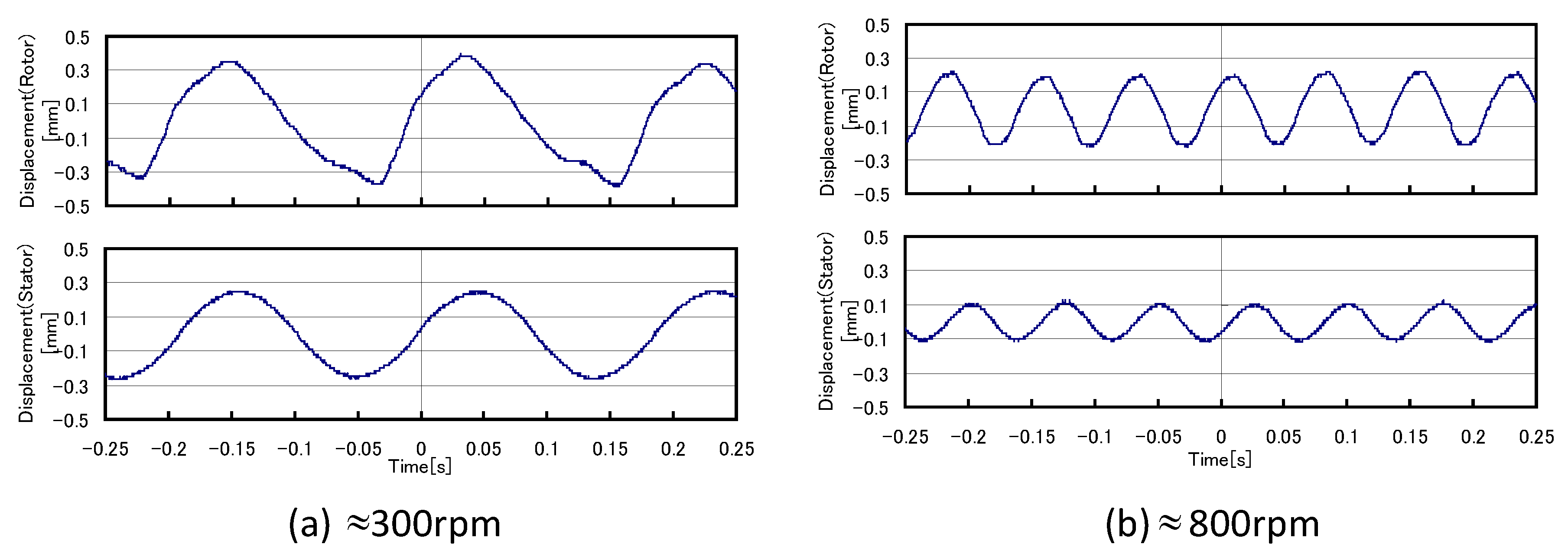
Figure 9 shows the free-run experimental results representing (a) the displacements of the flywheel rotor (upper figure) and stator (lower figure) at a speed of 300 rpm and (b) displacements of the flywheel rotor (upper figure) and stator (lower figure) at a speed of 800 rpm. Both displacements, at speeds of 300 rpm, are less than 0.3 mmo-p. The displacement phase of the flywheel rotor (upper figure in Figure 9a) is almost the same as the phase of the stator (lower figure in Figure 9a). This means that the displacement of the stator is caused by the vibration of the flywheel rotor. The displacement of the flywheel rotor (upper figure in Figure 9b), at speeds of 800 rpm, is less than 0.2 mmo-p. The displacement phase of the flywheel rotor (upper figure in Figure 9b) is almost the same as the displacement phase of the stator (lower figure in Figure 9b). This means that the displacement of the stator is caused by the vibration of the flywheel rotor. From the results from Figure 6, Figure 7, Figure 8 and Figure 9, it was found that the displacement of the stator is caused by the vibration of the flywheel rotor.

3.2. Free-Run Experimental Results in the Case of Fixed Stator

Since the displacement of the stator is caused by the vibration of the flywheel rotor, some experiments are performed with the stator fixed to the ground base. 
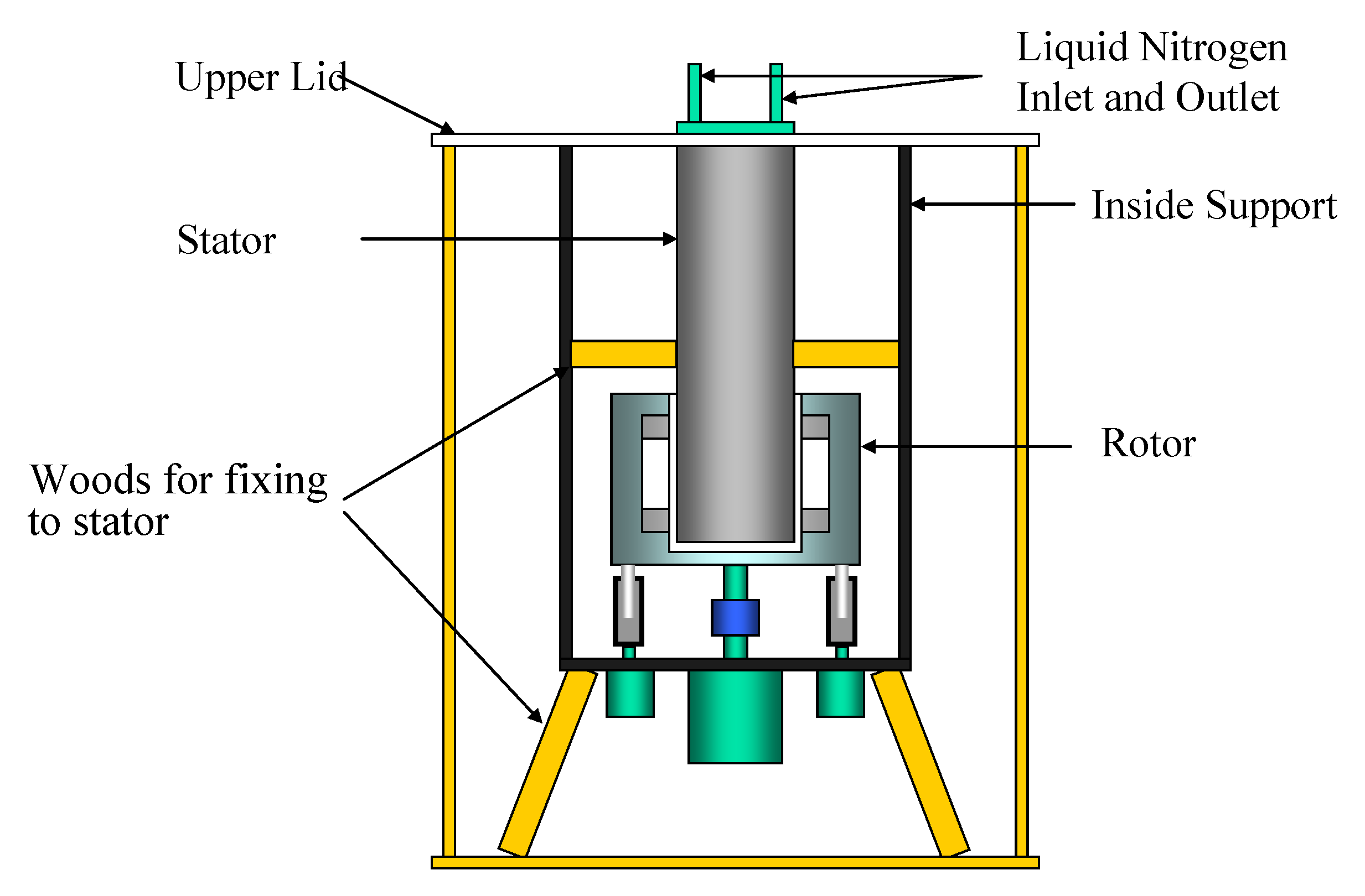
Figure 10 shows the schematic illustration of the flywheel energy storage system in the case of a fixed stator. As shown in the figure, the stator is fixed to the base ground using some woods.
Figure 11 shows the free-run experimental results in the case of a fixed stator, representing (a) a natural rotation decay curve, (b) displacement at an upper position of the rotor and (c) displacement at a lower position of the rotor. The results in the case of the fixed stator in Figure 11 correspond to the results in Figure 6. In Figure 6, the resonance rotation speeds at 300 rpm and 800 rpm are shown. However, there is no resonance rotation speed in Figure 11, as the stator is fixed to the ground base. In the case of making such types of suspended systems, it is important to fix the stator to the base ground.
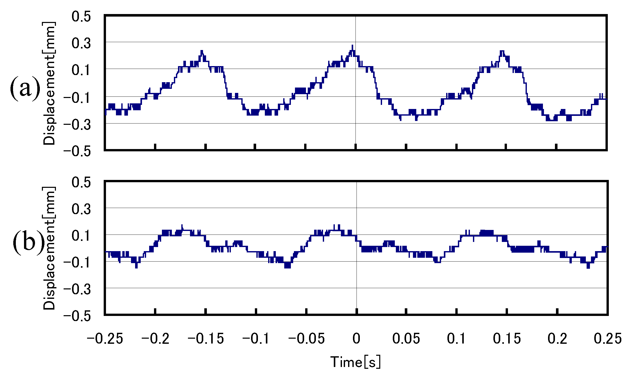
Figure 12 shows the free-run experimental results in the case of a fixed stator, representing (a) displacements of an upper position of the rotor (upper figure) and (b) displacements at a lower position of the rotor (lower figure) at a speed of 400 rpm. The displacement is less than 0.2 mmo-p, which is smaller than the displacement in Figure 6. The displacement phase of the upper figure in Figure 12a is almost the same as the phase of the lower figure in Figure 12a. This means that the flywheel rotor, in the case of a fixed stator, has the same cylindrical motion as that in the case of an unfixed stator.

3.3. Impulse Responses

The impulse responses are performed using the same setup as the free-run experiments performed in Figure 5, Figure 6, Figure 7, Figure 8 and Figure 9. The impulses are applied to the center position of the rotor and the stator at just the upper position of the rotor. That is, the impulses are applied to the same positions as those in Figure 8. The impulse responses for the stator and rotor are measured by using a fast Fourier transform (FFT) analyzer.
Figure 13 shows the impulse responses for (a) the rotor at a center position of the rotor in the case of an unfixed stator and for (b) the unfixed stator at just the upper position of the rotor, representing that the upper and lower figures show a displacement and power spectrum, respectively. As shown in the upper figure of Figure 13a, the displacement amplitude decays to 10% of the initial value within 8.0 s. However, the decay does not occur monotonously. This is because there are two dominant vibration modes, and these modes are combined with each other in the upper figure of Figure 13a. The lower figure of Figure 13a shows the peaks at 6.0 Hz and 14.0 Hz. These correspond to the vibration modes shown in the upper figure of Figure 13a. The peaks at 6.0 Hz and 14.0 Hz correspond to the vibration at 360 rpm and 840 rpm, respectively, as shown in Figure 6 and Figure 8. As shown in the lower figure of Figure 13b, the displacement amplitude decays to 10% of the initial value within 8.0 s. The decay occurs in the same manner as that in Figure 13a. This is also because there are two dominant vibration modes which are caused by the SMB.
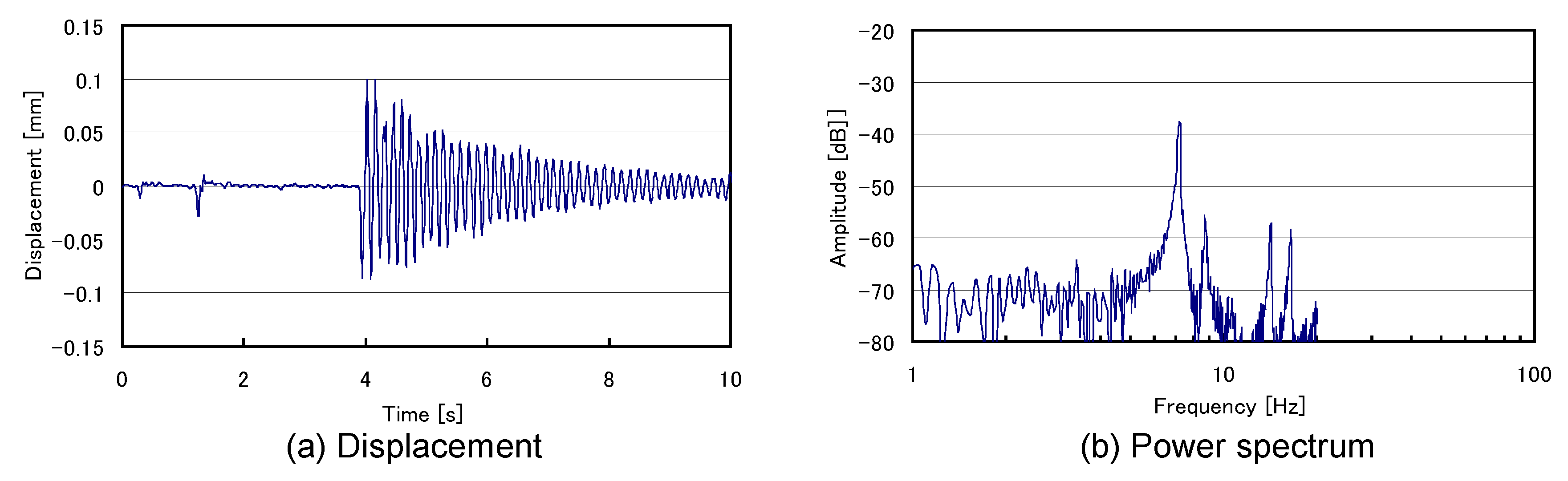
Figure 14 shows the impulse response for the rotor at the center position of the rotor in the case of a fixed stator, representing (a) displacement and (b) the power spectrum. As shown in Figure 14a, the natural damped vibration is observed, and the displacement amplitude decays to 10% of the initial value within 8.0 s. The result in Figure 14a is different from the result in Figure 13. In Figure 14, there is just one vibration mode. Figure 14b shows a large peak at 7.2 Hz, which corresponds to the vibration mode of SMB in Figure 14a. From the result in Figure 14, it was found that the peaks at 6.0 Hz and 14.0 Hz in Figure 13 are regarded as the vibration modes of the stator and SMB.

3.4. Free-Run Experimental Results in the Case of Applied Load

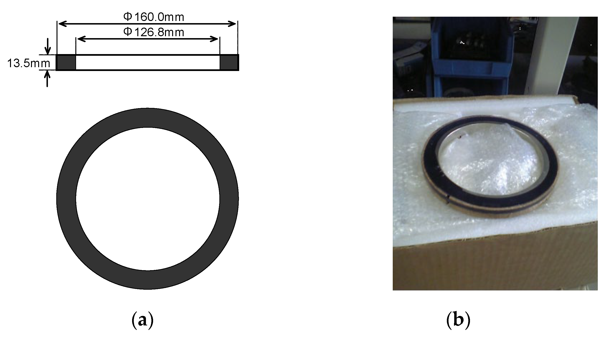
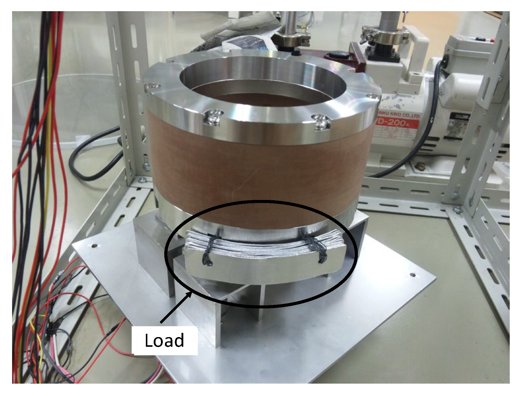
Figure 15 shows the flywheel rotor with a load attached to the bottom end. The load is made of a laminated aluminum plate and measures 115 mm × 25 mm × 1 mm × 12 pieces and is 100 g in weight. The free-run experiments were performed using the flywheel rotor with a load.
Figure 16 shows the free-run experimental results using the flywheel rotor with 100 g in the case of the fixed stator, representing (a) a natural rotation decay curve, (b) displacements at the center position of the rotor and (c) displacements of the stator at just the upper position of the rotor. The results in Figure 16 correspond to the results in Figure 11. During the natural rotation decay, a resonance rotation speed at 300 rpm is observed in Figure 16b,c, although there is no resonance rotation speed in Figure 11. This is caused by the attached load of 100 g. In other words, the load of 100 g amplifies the vibration of SMB. In the case of making this type of suspended system, it seems that it is important to fix the stator end. Figure 17 shows free-run experimental result showing (a) displacements at upper position of rotor and (b) displacements at lower position of rotor at a speed of 370 rpm.

4. Summary

A new superconducting flywheel energy storage system is proposed. The system comprises a radial-type SMB, an induction motor and some positioning actuators. The SMB is composed of the superconducting stator and the flywheel rotor.
From the free-run experimental results in the case of a fixed stator, it was found that the displacement of the stator is caused by the vibration of the flywheel rotor. The natural rotation decay curve, displacement at an upper position of the rotor and displacement at a lower position of the rotor were measured by using the free-run experiments in the case of a fixed stator. Although the resonance rotation speeds of 300 rpm and 800 rpm were observed in the case of the unfixed stator, there is no resonance rotation speed in the case of the fixed stator. In the case of the fixed stator, the displacement is less than 0.2 mmo-p except at 400 rpm.
Moreover, the impulse responses for the rotor in the case of an unfixed stator were performed. The experimental results for the impulse responses show that the displacement amplitude decays to 10% of the initial value within 8.0 s, that the decay does not occur monotonously and that there are two dominant vibration modes. The two vibration modes are caused by the SMB.
The impulse responses for the rotor in the case of a fixed stator were performed. The experimental results for the impulse responses show that the natural damped vibration is observed and that there is just one vibration mode. The vibration mode is caused by the SMB. In the case of making such types of suspended systems, it seems that it is important to fix the stator end.

Author Contributions

Conceptualization and investigation, M.K.; Methodology, experiment and measurement, M.K. and H.K.; Supervision, M.K.; Writing—original draft preparation, M.K.; Writing—review and editing, M.K. and K.-i.A.; Project administration, M.K. All authors have read and agreed to the published version of the manuscript.

Funding

This study is supported by the Iwatani Naoji Foundation.

Institutional Review Board Statement

Not applicable.

Informed Consent Statement

Not applicable.

Data Availability Statement

The data reported in this manuscript is accessible based on reasonable requests to the corresponding author.

Conflicts of Interest

The authors declare no conflict of interest.

References

  1. Moon, F.C.; Chang, P.-Z. High-speed rotation of magnets on high Tc superconducting bearings. Appl. Phys. Lett. 1990, 56, 397–399. [Google Scholar] [CrossRef]
  2. Hull, J.R.; Mulcahy, T.M.; Uherka, K.L.; Abboud, R.G. Low rotational drag in high-temperature superconducting bearings. IEEE Trans. Appl. Supercond. 1995, 5, 626–629. [Google Scholar] [CrossRef]
  3. Komori, M.; Tsuruta, A.; Fukata, S.; Matsushita, T. Superconducting bearing systems using high Tc superconductors. IEEE Trans. Appl. Supercond. 1995, 5, 634–637. [Google Scholar] [CrossRef] [Green Version]
  4. Okano, M.; Fuchino, S.; Agatsuma, K.; Tamada, N.; Ishii, I.; Onishi, T. Characteristics of a superconducting magnetic bearing. J. Jpn. Soc. Mech. Eng. C 1996, 62, 186–191. [Google Scholar] [CrossRef] [Green Version]
  5. Strasik1, M.; Hull, J.R.; Mittleider, J.A.; Gonder, J.F.; Johnson, P.E.; McCrary, K.E.; McIver, C.R. An overview of Boeing flywheel energy storage systems with high-temperature superconducting bearings. Supercond. Sci. Technol. 2020, 23, 1–5. [Google Scholar] [CrossRef]
  6. Werfel, F.N.; Floegel-Delor, U.; Rothfeld, R.; Riedel, T.; Goebel, B.; Wippich, D.; Schirrmeister, P. Superconductor bearings, flywheels and transportation. Supercond. Sci. Technol. 2010, 23, 1–16. [Google Scholar] [CrossRef]
  7. Ichihara, T.; Matsunaga, K.; Kita, M.; Hirabayashi, I.; Isono, M.; Hirose, M.; Yoshii, K.; Kurihara, K.; Saito, O.; Saito, S.; et al. Application of superconducting magnetic bearings to a 10 kWh-class flywheel energy storage system. IEEE Trans. Appl. Supercond. 2005, 15, 2245–2248. [Google Scholar] [CrossRef]
  8. Nagashima, K.; Seino, H.; Miyazaki, Y.; Arai, Y.; Sakai, N.; Murakami, M. Force density of magnetic bearings using superconducting coils and bulk superconductors. Railw. Technol. Inst. Rep. 2008, 2, 127–132. [Google Scholar] [CrossRef] [Green Version]
  9. Yamashita, T.; Ogata, M.; Matsue, H.; Miyazaki, Y.; Sugino, M.; Nagashima, K. Reliability verification of superconducting flywheel energy storage system and its application. Railw. Technol. Inst. Rep. 2017, 1, 47–52. [Google Scholar]
Figure 1. Schematic illustration of flywheel energy storage system.
Actuators 11 00215 g001
Figure 2. Superconducting stator representing (a) an overview photo of the stator and (b) the structure of the superconducting stator.
Actuators 11 00215 g002
Figure 3. Flywheel rotor attached to the bottom end of the superconducting stator.
Actuators 11 00215 g003
Figure 4. Permanent magnet of the rotor representing (a) the dimensions (b) photo.
Actuators 11 00215 g004
Figure 5. Experimental setup for a free-run experiment for measuring displacements at (upper) position of rotor and (lower) position of rotor.
Actuators 11 00215 g005
Figure 6. Free-run experimental results representing (a) the natural rotational decay curve, (b) displacement at an upper position of the rotor and (c) displacement at a lower position of the rotor.
Actuators 11 00215 g006
Figure 7. Free-run experimental results representing (a) displacements at the upper rotor (upper figure) and lower rotor (lower figure) at a speed of 300 rpm and (b) displacements at the upper rotor (upper figure) and lower rotor (lower figure) at a speed of 800 rpm.
Actuators 11 00215 g007
Figure 8. Free-run experimental results representing (a) a natural rotation decay curve, (b) displacement at the center position of the rotor and (c) displacement of the stator in just the upper position of the rotor.
Actuators 11 00215 g008
Figure 9. Free-run experimental results representing (a) the displacements of the flywheel rotor (upper figure) and stator (lower figure) at a speed of 300 rpm and (b) displacements of the flywheel rotor (upper figure) and stator (lower figure) at a speed of 800 rpm.
Actuators 11 00215 g009
Figure 10. Schematic illustration of the flywheel energy storage system in the case of a fixed stator.
Actuators 11 00215 g010
Figure 11. Free-run experimental results in the case of a fixed stator, representing (a) a natural rotation decay curve, (b) displacement at an upper position of the rotor and (c) displacement at a lower position of the rotor.
Actuators 11 00215 g011
Figure 12. Free-run experimental results in the case of a fixed stator, representing (a) displacements of an upper position of the rotor (upper figure) and (b) displacements at a lower position of the rotor (lower figure) at a speed of 400 rpm.
Actuators 11 00215 g012
Figure 13. Impulse responses for (a) the rotor at a center position of the rotor in the case of an unfixed stator and for (b) the unfixed stator at just the upper position of the rotor, representing that the upper and lower figures show a displacement and power spectrum, respectively.
Actuators 11 00215 g013
Figure 14. Impulse response for the rotor at the center position of the rotor in the case of a fixed stator, representing (a) displacement and (b) the power spectrum.
Actuators 11 00215 g014
Figure 15. Rotor attached with a load of 100 g.
Actuators 11 00215 g015
Figure 16. Free-run experimental results using the flywheel rotor with 100 g in the case of the fixed stator, representing (a) a natural rotation decay curve, (b) displacements at the center position of the rotor and (c) displacements of the stator at just the upper position of the rotor.
Actuators 11 00215 g016
Figure 17. Free-run experimental result showing (a) displacements at upper position of rotor and (b) displacements at lower position of rotor at a speed of 370 rpm.
Actuators 11 00215 g017
Publisher’s Note: MDPI stays neutral with regard to jurisdictional claims in published maps and institutional affiliations.

