Abstract
In a narrow surgical space, flexible surgical instruments offer advantages over rigid counterparts in terms of operational dexterity. To this end, a flexible surgical instrument was designed in this study to realize dexterous motion using multiple segments in a series under wire-driven operation, satisfying the motion requirements of minimally invasive surgical operations. The forward and inverse kinematics of the instrument were solved using the geometrical method and the Newton–Raphson method, and the kinematics models were verified using a prototype. Experiments were conducted to verify the performance of the prototype device; the results showed that the time required for a kinematic solution was less than 0.1 ms. In addition, the device could flexibly reach the designated position in a narrow and long operating space and had excellent motion accuracy. Finally, it was verified that the prototype device had a certain load capacity.
1. Introduction
With the rapid development of robot-assisted minimally invasive surgery (RMIS), the accuracy and dexterity of surgical operations have improved [1,2,3,4,5]. At present, the primary surgical instruments for RMIS are rigid instruments with wrist motions in which the ability to adjust the posture of rigid instruments in a narrow surgical environment is not sufficient compared with flexible surgical instruments [6]. Flexible surgical instruments have the advantages of multiple degrees of freedoms (DOFs) and good environmental adaptability [7], rendering them highly suitable for performing surgical tasks in narrow workspaces. To meet the requirements for reaching a target position in a small surgical space, flexible surgical instruments are often required to have dexterity equivalent to that of a human hand [8]. In addition, since the surgical instrument needs to be able to probe into the body cavity to complete a surgical task, considering the limitations of the working space, the surgical instruments are required to have smaller size parameters [9]. These requirements increase the difficulty of designing and manufacturing flexible instruments. Moreover, redundant high degrees of freedom (DOFs) also increase the difficulty of accurately establishing kinematic models [10,11,12].
In recent years, several researchers have conducted studies on flexible surgical instruments. Ding et al. designed a single-port surgical robotic system [13,14]. The system included two 6-DOF flexible continuum manipulator arms, and the flexible continuum joint near the poke end was passively supported by a six-bar mechanism. Due to the singularity point of the six-bar mechanism and the configuration of two flexible joints connected in a series, the system had low dexterity, slow operation, and a small load capacity; thus, it could not complete complex surgical tasks. Xu et al. developed a single-hole robot [15,16]. The robot manipulator was composed of two flexible continuum joints. Each flexible continuum joint was driven by three superelastic nickel–titanium memory alloy wires. The continuum was completely connected to form a whole, and the rear-end driving device generated forward and backward movement by pulling the nickel–titanium memory alloy wire, thereby driving the joints of the continuum to perform overall deflection. The system has the advantage of being compact but has a small end-load capacity. Shang et al. designed a flexible surgical instrument using a nickel–titanium alloy tube as a supporting framework [17] and achieved bending by cutting grooves on the tube wall of the iron–nickel alloy tube. Then, they optimized the design of the grooves. It could better resist the axial compression deformation caused by the tension force of the wire. Compared with an articulated joint configuration, this structure had higher flexibility, but its precise motion control was more complicated. Conrad et al. developed interleaved continuum-rigid manipulation with a soft, flexible robotic manipulator [18]. They used flexible shafts to remotely drive cable motion in the manipulator. While the 1-DOF flexible continuum portion of the manipulator was small (6 mm in diameter), the additional 2-DOF located in the proximal section were larger and contained complex miniature gear transmissions. Mao Z et al. proposed a soft fiber-reinforced bending finger with three chambers actuated by ECF (electro-conjugate fluid) pumps [19]; a flexible bending finger with three chambers can easily realize 2-DOF motion. This research has guiding significance for soft robotic arms, especially for minimally invasive surgery with variable stiffness. Fionnuala et al. presented a design strategy that takes a kinematic trajectory as its input and uses analytical modeling based on nonlinear elasticity and optimization to identify the optimal design parameters for an actuator that will follow this trajectory upon pressurization [20]. Finally, they verified the modeling method through experiments. This research can be used to guide the design of soft actuators, thereby speeding up the design process. Jones et al. proposed a method for solving the kinematics of a flexible robot [21] by analyzing the robot’s mechanism, establishing a coordinate system, and using the geometric relationship and D-H method to solve the relationship between the pose and the three lines of the control end. Although this method can accurately obtain the kinematic equations, the solution process is too complicated, which is not conducive to the kinematics solution of complex structures. Neppalli et al. presented a geometrical approach for solving the inverse kinematics of a continuum robot [22]. The position of each node on the continuum structure was assumed to be known and then compensated for the resulting change in direction; however, this approach cannot provide a general solution form. Cai et al. designed and conducted a kinematics analysis of a series-parallel hybrid flexible surgical instrument [23]. The author obtained the kinematics equation of the robot according to the physical properties of the rigid Hooke hinge and the rod length constraint. Although this method can solve the relationship between each branch chain of the parallel mechanism and the rotation angle of the platform, due to the structural characteristics of the mechanism, it is not necessary to consider the kinematic characteristics of each branch chain, which has the disadvantage of lower accuracy. Kim et al. designed a wire-driven flexible manipulator (WDM), using the robotics toolbox to model the WDM and verify its kinematics [24]. An optimized IK method was developed for the inverse kinematics solution of a WDM, and a geometric approximation was used as an initial guess for numerical optimization. Although this method does not provide an exact solution, it gives an approximate value of the angle of bending in WDM. Therefore, such an appropriate starting point can reduce the convergence time or even avoid local optimization. This method can provide fast and reliable inverse results, simplify kinematics calculations, and improve the real-time performance of the robot. However, it neither considers drive-by-wire control nor does it demonstrate the effectiveness of the method through prototype experiments. In summary, for kinematically redundant and flexible robotic structures, the standard Denavit–Hartenberg convention [25] for describing the position relationships of prismatic or revolute joints is not well suited for flexible robots, the development of kinematics to operate such robots repeatedly and reliably under real-time control remains an open research topic.
In this study, a flexible surgical instrument was developed that realizes dexterous motion by means of the structure of a segment connected by a pin roll in sequence. Its forward kinematics were solved using geometrical methods, and the Newton–Raphson method was used to solve the inverse kinematics. The performed experiments verified that the method was quick and accurate. Finally, it was verified that the flexible surgical instrument had good dexterity in a long and narrow space and had a certain load-bearing capacity.
2. Structural Design of the Flexible Surgical Instrument
At present, soft robots are generally driven by cable active polymers, pneumatic artificial muscles, deformable memory alloys, embedded pneumatic networks, and other elastic materials to achieve flexible motion and ensure dexterity [26,27,28,29]. In this study, a wire-driven mode was adopted for flexible surgical instrument design, because it retains the advantages of force and motion transmission despite the limitations of structural dimensions [30]. Surgical instruments for MIS mostly have a diameter of 5, 8, or 10 mm in clinical practice. Considering the implementation of the overall strength and flexible function of the instrument and the convenience of use with the sleeve needle, the diameter used in this study was 8 mm. The surgical instrument was composed of an end effector, a flexible part, a rigid rod, and a drive box, as shown in Figure 1.
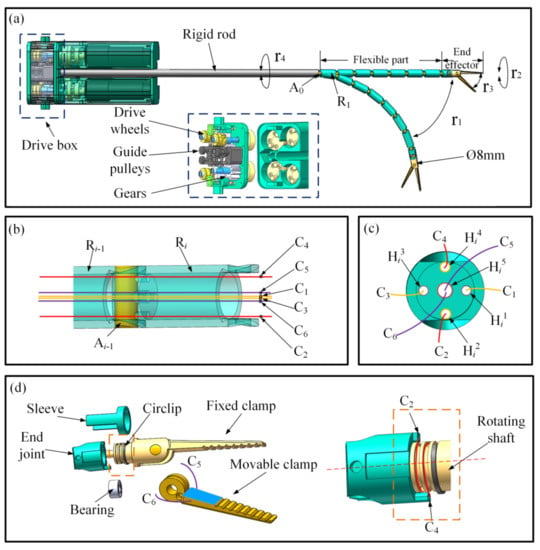
Figure 1.
Structural analysis of the flexible surgical instrument: (a) surgical instrument; (b) connection of two segments; (c) traction cables of the flexible part; (d) structure of the clamps.
As shown in Figure 1a, the flexible part was composed of seven cylindrical segments connected in sequence by pin rolls, and the number of segments could be increased or decreased with the requirements of the operating space. The segments are marked Ri in turn (i represents the number of segments, and the segment connected to the rigid rod is marked as R1), and the pin rolls connecting the two segments are marked Ak in turn (k represents the number of pin rolls, and the pin roll connecting the rigid rod is marked as A0). The front segment was connected to the next segment by a pin, the stiffness of the flexible section could be increased by connecting the segments in a series with the pin rolls, and each segment could be bent approximately 15° around the center axis of the pin shaft, such that the maximum bending angle of the instrument’s flexible portion was 105°.
The connection between two segments is shown in Figure 1b, where holes Hij (j represents the number of holes) were used to pass through the cables on each segment. The end surface of the segment is shown in Figure 1c, where the four small circular holes, Hi1–Hi4, were used to pass the four cables, C1–C4, and the central hole, Hi5, was used to pass two cables, C5 and C6. The curved DOF r1 of the flexible components was controlled by cables C1 and C3; when cable C1 was pulled, cable C3 was released, and the instrument bent to cable C1’s side, and vice-versa. The length of each segment was 20 mm, and the flexible portion of the instrument was 140 mm long, allowing for a large range of motion.
The surgical clamps were the end effectors of the surgical instrument, and the designed surgical clamps had an opening and closing DOF and a rotational DOF. For operational and control convenience, as shown in Figure 1d, the surgical clamps were designed so that one was movable and one was fixated. The fixed surgical clamp was designed with a rotating shaft and was connected through the sleeve and the end joint. The circlip effect was to limit the operation of the surgical clamp’s axial movement, the bearing was used to reduce the friction between the rotating components and to maintain the roller alignment when the load was loaded. The rotational DOF, r2, of the end effector was controlled by the cables C2 and C4, and in order to ensure that the traction direction of C2 and C4 rotated along the rotating shaft, cables C2 and C4 were guided through a 90 degree turn to deliver force perpendicular to the rotating shaft. Two grooves are designed in the rotating shaft, and two small-stepped holes were made on the two grooves. The ends of the cables C2 and C4 were fixed in the stepped holes and then wrapped in the grooves and passed through holes Hi2 and Hi4. When C4 was pulled, C2 was released, and the surgical clamp rotated clockwise around the central axis; whereas, when C2 was pulled, C4 was released, and the surgical clamps rotated counterclockwise around the central axis. It is worth mentioning that the fixed clamp and rotation structures were integrated, which simplified the end effector structure. The rotation angle of the rotating shaft could reach ±90°. The opening and closing DOF, r3, of the movable surgical clamp was driven by cables C5 and C6. The opening and closing motions of the clamp are shown in Figure 1d. The two cables C5 and C6 were knotted and fixed on the movable clamp. When C5 was pulled, the movable clamp was opened, and when C6 was pulled, the movable clamp was closed.
As shown in Figure 1a, the flexible instruments also had an overall rotational DOF of r4, and the drive gear drove the rigid rod to rotate, thus driving the overall rotational movement of the flexible instrument. There were drive wheels and guide pulleys inside the drive case, and the cables were guided by the pulleys and fixed to the drive wheels. In addition, several DC motors were mounted on the bottom of the drive case, each connected to a drive wheel. The motor rotated to drive the cables and achieve segmentation movement.
3. Kinematics Modeling and Analysis
When the flexible part of a surgical instrument is bent, the bending curvature of each segment is constantly based on the motion characteristics of the instrument [31]; thus, the bending angle of each segment is equal. The flexible instrument in Reference [31] was designed with multiple bending DOFs, and the forward kinematics of the instrument were established using the spatial geometry method, which increases the difficulty of kinematic modeling, and the multiple bending DOFs also increase the difficulty of precisely controlling flexible instruments. The flexible instrument designed in this paper had a bending DOF, which avoided redundant DOFs. When the flexible instrument does not rotate in motion, the instrument is only bent in a plane, and it is easy to establish the forward kinematics of the instrument using the plane geometry method, and it is convenient for precise control of the instrument. The following describes the kinematic model of a flexible instrument.
To describe the motion state of the segment Ri, the coordinate system oi−1−xi−1yi−1zi−1 was built at the geometric center of the pin roll, Ak−1. The positive direction of the xi−1 axis was pointed from oi−1 to the hole Hi1, the positive direction of the yi−1 axis was pointed from oi−1 to the hole Hi4, and the positive direction of the zi−1 axis was determined by the right-hand rule. The method of establishing the coordinate system oi−xiyizi was similar to the coordinate system oi−1−xi−1yi−1zi−1, which is shown in Figure 2.
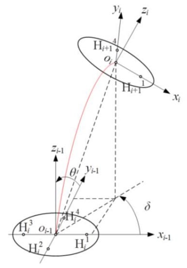
Figure 2.
Kinematics model of a single segment.
The motion of segment Ri can be decomposed into two angles: the bending angle θ of the segment Ri around the pin roll and the rotation angle δ around the zi−1 axis. The length of segment Ri is denoted by a, and the position oi (oix, oiy, and oiz) in the system oi−1-xi−1yi−1zi−1 can be obtained as follows:
The rotation angle δ can be obtained by the coordinates of oi:
To analyze the kinematics of the flexible instrument, a multisegment coordinate system was established through the same method used for a single segment. The base coordinate system o0-x0y0z0 was established at the geometric center of the pin roll, A0, and the coordinate system o1-x1y1z1 was established at the geometric center of the pin roll, A1, etc. P (Px, Py, and Pz) represents the position of the end effector, which is shown in Figure 3.
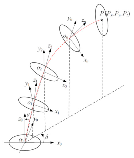
Figure 3.
Kinematics model of the flexible surgical instrument.
The flexible part of the instrument is composed of n segments connected by pin rolls in series, the length of each segment is denoted by a, the length of the end effector is denoted by b, and the position on (onx, ony, and onz) of the pin roll, An, and P (Px, Py, and Pz) of the end effector in the base system o0-x0y0z0 can be obtained as follows:
RMIS generally uses a master–slave operation mode, and the motion information of the master manipulator controlled by the surgeon is mapped onto the surgical instrument to follow the operation performed by the surgeon’s hands. To ensure that the surgical instrument can reach the mapped position, it is necessary to solve the inverse kinematics of the instrument to obtain the motion of each segment. The motion of the instrument can be decomposed into bending angle θ and rotation angle δ, which can be calculated by formulas (3) and (4).
The bending angle θ of the designed instrument was in the range of 0–15°, the rotation angle δ was in the range of 0–360°, the length a of each segment was 20 mm, the length b of the end effector was 50 mm, and the number of the segment was seven. According to the above forward kinematics analysis, the working space of the flexible instrument was calculated in MATLAB software. As shown in Figure 4, the working space of the flexible instrument was approximately half a sphere with a radius of 150 mm. A flexible instrument can reach any position in the surgical space with several DOFs of motion.
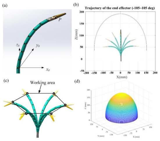
Figure 4.
Workspace of the flexible instrument: (a) instrument coordinate system; (b) instrument plane motion trajectory; (c) instrument workspace trajectory; (d) instrument workspace.
In this study, the bending angle θ was solved using Newton–Raphson method following the basic equations:
where f(θ) is the equation containing the variable θ, θn represents the value of the variable θ at the nth iteration, and ∆θn is the difference of the variable θ at two adjacent iterations. When solving the equations, θ0 is used as the initial iteration point to start the iterative calculation, ∆θn can be obtained by Equation (8), θn+1 can be obtained by Equation (7), and so forth until ∆θn reaches the required error range, where θn is the solution of the system of equations. Thus, the bending angle θ can be obtained.
The bending motion of the surgical instrument was achieved by controlling the lengths of the two cables, C1 and C3, and the relationship between the segment bending angle θ and the lengths of cables C1 and C3 was calculated through the following steps. As shown in Figure 5a, Sij is the center of the lower end face of hole Hij before the segment Ri is bent. Sij’ is the center of the lower end face of hole Hij after the instrument is bent, and Fij is the center of the upper-end face of hole Hij. For each segment, there is a hollow cavity and a solid part with holes Hij. The diameter of the holes Hij is the same as the diameter of the cables. Thus, when the segment Ri bends at an angle of θ, the length of the cables in holes Hij can be considered to remain constant. The length of cable C1 changes between the lower-end face Si1 and the upper-end face Fi−11, and the change in the length of cable C1 is denoted by ∆C1. The length of cable C3 changes between the lower-end face Si3 and the upper-end face Fi−13, and the change in the length of cable C3 is denoted by ∆C3. The changes in the lengths of cables C1 and C3 are shown in Figure 5b.
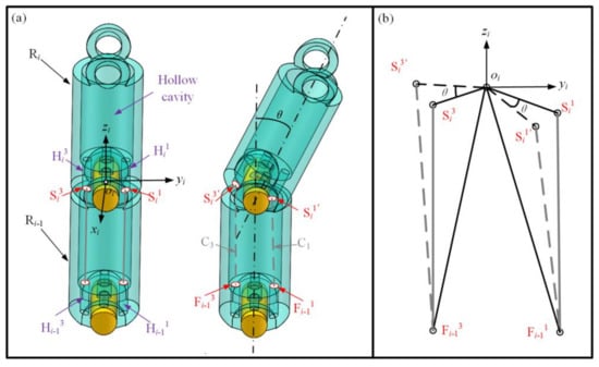
Figure 5.
Analysis of the changes in cable length: (a) state of the segment before and after bending; (b) change in the length of cables C1 and C3.
In Figure 5b, before the segment Ri is bent, the length of cable C1 is equal to , which is the distance between Si1 and Fi−11, and the length of cable C3 is equal to . After the segment Ri is bent at an angle of θ, the length of cable C1 is equal to , and the length of cable C3 is equal to . In triangle Si1’oiFi−11 and triangle Si3’oiFi−13, we can obtain the following from the cosine theorem:
Thus, the changes in the length of C1 and C3 are:
When the flexible part of the surgical instrument is bent, the bending curvature of each segment is constant [30], and the bending angle θ of each segment is equal. When each segment is bent at angle θ, the total length change of cable C1 is n*∆C1, and the total length change of cable C3 is n*∆C3, where n is the number of segments. Through the above analysis, the amount of change in the length of the cables can be obtained, and the corresponding motion of the motor can then be calculated to achieve joint movement.
4. Experiment
In order to verify the accuracy of the kinematics and some functions of the flexible instruments, we built a robot system that adopted a master–slave control method [32,33]. As shown in Figure 6a, the flexible instrument was installed at the end of the telecentric mechanism of the robot slave hand part. Figure 6b shows the main manipulator of the robot system. Figure 6c shows the flexible surgical instrument, which used stainless-steel 304 material for the model. The flexible part was composed of multiple segments, the outer diameter of the end effector was 8 mm, and cables of different lengths and with diameters of 0.5 mm were used for power transmission. The cables used in this instrument were produced by Japan N.M.R Company, the structure was 7 × 6-IWR, the standard breaking load was 0.176 KN, the standard weight was 0.81 g/m, and the cables’ material was high-strength and high-melting tungsten, which is suitable for complex mechanical driving or repeated bending requiring a long service life. The movements of the flexible instrument and robotic arms were driven by motors.
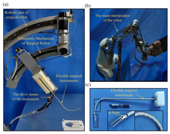
Figure 6.
The prototype of the developed flexible surgical instrument: (a) minimally invasive surgical robot system; (b) the main manipulator of the robot; (c) flexible surgical instrument.
In order to measure the range of motion of the end effector of the flexible instrument and the effect of real-time control, we controlled the flexible instrument to swing in the bending plane (the range of each swing was approximately 30°), and we recorded the corresponding time of each swing. Figure 7 illustrates the practical effect of the flexible instrument in bending degrees of freedom of ±90 swing. As shown in Figure 7b, we gave the motor the proper running speed, and the time of each movement was approximately 1 to 2 s. We believe that, in the need for visual feedback, in some cases, the proposed instrument can be moved very quickly to the desired position. During the experiment, no obvious problems were encountered such as the failure of wires and cables.
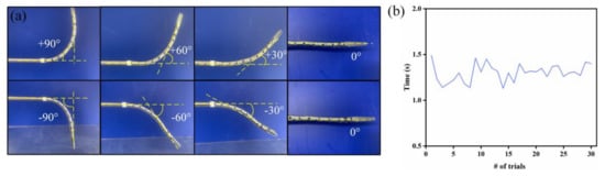
Figure 7.
Demonstration of flexible instrument bending motion: (a) demonstration of the flexible instrument’s bending motion; (b) thirty degrees of response time per movement.
In order to verify the accuracy of inverse kinematics, we extracted the bending trajectory of the flexible instrument. The position given by the master–slave mapping was compared with the position given by the kinematic equation calculation. For the given position, the bending angle θ of each segment can be calculated through the inverse kinematics equation. Through the relationship between the wire rope length variation and the bending angle, the corresponding wire rope length variation controlled by the motor could be calculated, and the motor could be controlled to make the end of the instrument run to the given position. A motion capture system (Fusion Track 500, Atracsys, Puidoux, Switzerland) was used to collect movement information and obtain the actual motion trajectory through the collected position information.
As shown in Figure 8, an optical reflector was fixed to the end effectors of the instrument. Data were collected from the motor’s encoder, and the resulting values were applied to the forward kinematics equation to obtain the theoretical trajectory of the end of the instrument. The theoretical and actual motion trajectories of the flexible device are shown in Figure 9a.
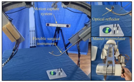
Figure 8.
Actual trajectory measurement of the flexible instruments.
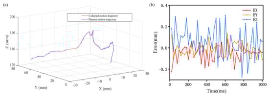
Figure 9.
Analysis of the planned and collected trajectories: (a) trajectory of the collected movement and the planned movement of the instrument; (b) deviation between the actual position and the given position.
Taking the points of the trajectory in MATLAB, the coordinates of the obtained points were entered into the inverse kinematics solver, and the inverse kinematics were obtained in a very short period of time. The position deviations of the planned and collected trajectories are shown in Figure 9. Ex is the deviation along the direction of the x-axis, Ey is the deviation along the direction of the y-axis, and Ez is the deviation along the direction of the z-axis. As shown in Figure 8, the maximum deviation of the simulation results for each coordinate point did not exceed 0.4 mm. Because the positioning accuracy of human vision is less than 0.1 mm [34], the accuracy could meet a doctor’s operational needs. The experiments show that the actual motion trajectory results were highly coincident with the theoretical calculation trajectory results, which verifies the accuracy of the inverse kinematics, and the accuracy of the instrument also meets the operational needs of doctors. In addition, it took less than 0.1 ms to calculate the results of the inverse kinematics equations on a computer with the Win10 operating system, 8 GB memory, and Intel(R) Core (TM) i5-8500 processor (3.00 GHz). Thus, this method has a high processing speed and can achieve real-time control.
In order to measure the trajectory accuracy of the multiple movements of the flexible instrument, we defined a trajectory as a three-dimensional space arc, used the main hand to control the end of the instrument to reach the defined space trajectory arc, and used the motion capture system to measure the actual arc trajectory of the end of the instrument. The repeated measurement times, the defined three-dimensional space trajectory, and the actual three-dimensional motion trajectory are shown in Figure 10a. The blue arc traces represent the defined trajectory, and the arc traces of other colors are the actual measured trajectories. From Figure 10a, we can see that the actual trajectories coincided highly with the defined arc trajectory. Figure 10b shows the errors between the actual arc tracks and the defined track; the error between the expected trajectory and the actual trajectories of the flexible surgical instrument in the x, y, z, and other directions was less than 0.2 mm. The experimental results show that the instrument can be well controlled for fine operation and master–slave operation.
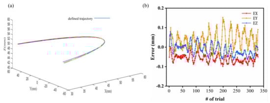
Figure 10.
Repeated experiments for a given trajectory: (a) repeated experiments for a given trajectory; (b) the deviation between the actual position and the given position.
To verify the working performance of the flexible instrument, we used a custom-designed master manipulator to control the flexible instrument to grasp beads from the four positions of A, B, C, and D and place them in the middle target position. The experimental pictures are shown in Figure 11a, which show that the device had good maneuverability. To verify the operational performance of the flexible instrument in narrow and long spaces, we used a master manipulator to control the instrument to arrive at the position of the beads in a narrow transparent container without touching the inner wall of the transparent container. The experimental pictures are shown in Figure 11b, which prove that the instrument could flexibly reach the target position in a narrow and long space.
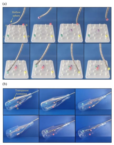
Figure 11.
Operational experiments: (a) grasping beads with the instrument; (b) experiments in a narrow and long space.
In order to facilitate the posture adjustment after the flexible instrument reached the target position, a rotating DOF was designed at the end of the instrument, which enabled the surgeon to adjust the opening direction of the surgical forceps. We carried out corresponding experimental measurements on the accuracy of the end rotating shaft through a Hexagon’s Articulated Arm Three Coordinates Measuring Machine. Before the test, we calculated the relationship between the corresponding drive motor parameters and the motion of the rotating shaft. Through calculation, the motor was controlled to rotate the rotating shaft 45° clockwise at every interval, and the angle was measured after each rotation, and after four clockwise rotations, the rotation was repeated in the counterclockwise direction. The measurement of the rotation angle was carried out with a hexagonal articulated arm CMM. This required surface contact measurements, each of which only required the probe to lightly touch the same surface of the rotating shaft. The test process is shown in Figure 12a, and the value of the angle error is shown in Figure 12b. As can be seen from the chart, the highest single-shot error was 4°, and the maximum cumulative error was 6°.
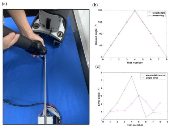
Figure 12.
Tests of forceps rotation: (a) measurement of the angle of the rotation axis; (b) rotational measurement error; (c) rotational measurement error.
To verify the carrying capacity of the flexible instrument, a set of weight-lifting experiments were then carried out to quantify the payload capabilities of the arms. As shown in Figure 13a, an arm was commanded to four representative configurations (angles of 30°, 45°, 60°, and 90°) as illustrated in Figure 13c. Different weights (10 to 50 g in increments of 10 g) were hung on the gripper. Deviation of the end of the instrument was measured, and the deflections are plotted in Figure 13c. It can be observed that when these small weights were applied to the gripper, the arm underwent small deflections. The deflections were considered small compared to the overall length of the manipulation arm (approximately 150 mm). Due to the presence of a human operator in the teleoperation with 3D visual guidance, these small deflections could be knowingly corrected by the user’s inputs. On the other hand, the 150 mm long manipulation arm was strong enough to lift a 200 g weight, as shown in Figure 13b, which proves that the instrument had a good load-bearing capacity.
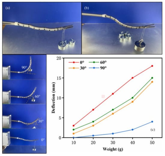
Figure 13.
Experiments on the bending motion under load: (a) small weights; (b) extreme condition; (c) deflections caused by the small weights.
In order to verify the reliability of flexible instruments in the surgical process, live animal organs were used as surgical objects. However, due to the lack of animal laboratories and the lack of medical equipment, such as pneumoperitoneum and anesthesia, isolated animal organs were used in the experiment instead of living animals for robotic surgery.
The task of this experiment was to excise and extract pig liver organs. The experiment used fresh pig liver organs as shown in Figure 14. The horizontal size was approximately 28 cm, the vertical size was approximately 18 cm, the height was approximately 7 cm, and the weight was 1.48 kg. Before the experiment, the fresh pig liver was kept in a sterile environment of 50% glycerol saline to maintain the physiological activity characteristics of the pig liver as much as possible. The operation’s process is shown in the figure. During the operation, surgical scissors were used to peel off part of the liver tissue, and at the same time, the flexible instrument’s forceps were controlled to pull part of the liver tissue. Finally, the operation was completed, and part of the liver tissue was successfully peeled off and taken out.
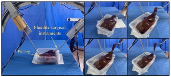
Figure 14.
Pig liver tissue stripping and extraction experiments.
The operation experiment was carried out by a thoracic and abdominal surgeon, who provided medical guidance on the subject, and, finally, the gallbladder removal was successfully completed. A total of three surgical experiments were performed, and one operation was performed each time, with an average operation time of 25 min. The excision operation experiment on part of pig liver tissue was completed smoothly, which verifies that the flexible surgical instrument has high operational reliability.
5. Conclusions
In this paper, a flexible surgical instrument was proposed that realizes dexterous motion by a series of segments connected by pin rolls in a sequence. The forward kinematics and inverse kinematics were solved via geometrical and Newton–Raphson methods. The experiment showed that the actual motion trajectory results were highly coincident with the theoretical calculation trajectory results, which verified the accuracy of the inverse kinematics. Meanwhile, experiments showed that the flexible instrument could operate satisfactorily under master–slave control and had good performance in narrow and long spaces. In addition, the surgical instrument had a good load-bearing capacity.
To facilitate the disinfection of the surgical instruments, the part of the flexible surgical instrument that enters the human body should be encapsulated with Teflon. In the future, we will investigate the built kinematics for the movement control of an instrument encapsulated with Teflon and optimize the kinematics model based on the experimental results.
Author Contributions
Conceptualization, X.J. and X.L.; methodology, X.L.; validation, C.W.; formal analysis, C.W.; investigation, C.W.; resources, X.L.; data curation, J.L.; writing—original draft preparation, C.W.; writing—review and editing, X.J.; visualization, C.W.; supervision, X.J. and X.L.; project administration, X.J.; funding acquisition, X.L. All authors have read and agreed to the published version of the manuscript.
Funding
This work was supported by the National Natural Science Foundation of China (Grant No. 51975241), the Opening Foundation of the State Key Laboratory of Digital Manufacturing Equipment and Technology (Grant No. DMETKF2021008), the Key R&D Project of Jilin Province Science and Technology Department (Grant No. 20200404150YY), and the Jilin Province Industrial Technology Research and Development Project (Grant No. 2019C048-3).
Institutional Review Board Statement
Not applicable.
Informed Consent Statement
Not applicable.
Data Availability Statement
Not applicable.
Conflicts of Interest
The authors declare no conflict of interest.
References
- Marescaux, J.; Rubino, F. The ZEUS robotic system: Experimental and clinical applications. Surg. Clin. N. Am. 2003, 83, 1305–1315. [Google Scholar] [CrossRef]
- Marescaux, J.; Leroy, J.; Gagner, M.; Rubino, F.; Mutter, D.; Vix, M.; Butner, S.E.; Smith, M.K. Transatlantic robot-assisted telesurgery. Nature 2001, 413, 379–380. [Google Scholar] [CrossRef]
- Guthart, G.S.; Salisbury, J.K. The Intuitive TM Telesurgery System: Overview and Application. In Proceedings of the IEEE International Conference on Robotics & Automation, San Francisco, CA, USA, 24–28 April 2000; pp. 618–621. [Google Scholar]
- Taylor, R.H.; Funda, J.; Eldridge, B.; Gomory, S.; Gruben, K.; LaRose, D.; Talamini, M.; Kavoussi, L.; Anderson, J. A telerobotic assistant for laparoscopic surgery. IEEE Eng. Med. Biol. Mag. 1995, 14, 279–288. [Google Scholar] [CrossRef]
- Maeso, S.; Reza, M.; Mayol, J.A.; Blasco, J.A.; Guerra, M.; Andradas, E.; Plana, M.N. Efficacy of the Da Vinci surgical system in abdominal surgery compared with that of laparoscopy: A systematic review and meta-analysis. Ann. Surg. 2010, 252, 254–262. [Google Scholar] [CrossRef] [PubMed]
- Yu, X.J. Kinematics and Dynamics Modeling and Visual Servo Control for Soft Robotic Manipulator. Master’s Thesis, Shanghai Jiao Tong University, Shanghai, China, 2013; pp. 53–54. [Google Scholar]
- Calisti, M.; Giorelli, M.; Levy, G.; Mazzolai, B.; Hochner, B.; Laschi, C.; Dario, P. An octopus-bioinspired solution to movement and manipulation for soft robots. Bioinspir. Biomim. 2011, 6, 036002. [Google Scholar] [CrossRef] [PubMed] [Green Version]
- Madhani, A. The Black Falcon: A Teleoperated Surgical Instrument for Minimally Invasive Surgery. In Proceedings of the IEEE International Conference Intelligent Robots & Systems, Victoria, BC, Canada, 17 October 1998. [Google Scholar]
- Mittelstadt, B.D. The Evolution of a Surgical Robot from Prototype to Human Clinical Use. In Proceedings of the First International Symposium on Medical and Computer Assisted Surgery (MRCAS’94), Pittsburgh, PA, USA, 22–24 September 1994. [Google Scholar]
- Jones, B.A.; Walker, I.D. Practical Kinematics for Real-Time Implementation of Continuum Robots. IEEE Trans. Robot. 2006, 22, 1087–1099. [Google Scholar] [CrossRef] [Green Version]
- Liu, Y.C.; Yu, Y.Q.; Jiang, C.F. Research status of flflexible robot. Mach. Des. 2003, 20, 4–8. [Google Scholar]
- Wang, T.; Hao, Y.; Yang, X.; Wen, L. Soft Robotics: Structure, Actuation, Sensing and Control. J. Mech. Eng. 2017, 53, 1–13. [Google Scholar]
- Ding, J.; Goldman, R.E.; Xu, K.; Allen, P.K.; Fowler, D.L.; Simaan, N. Design and Coordination Kinematics of an Insertable Robotic Effectors Platform for Single-Port Access Surgery. IEEE/ASME Trans. Mechatron. 2012, 18, 1612–1624. [Google Scholar] [CrossRef] [Green Version]
- Bajo, A.; Goldman, R.E.; Long, W.; Fowler, D.; Simaan, N. Integration and Preliminary Evaluation of an Insertable Robotic Effectors Platform for Single Port Access Surgery. In Proceedings of the IEEE International Conference on Robotics and Automation, Saint Paul, MN, USA, 14–18 May 2012; pp. 3381–3387. [Google Scholar]
- Chen, Y.; Zhang, C.; Wu, Z.; Zhao, J.; Yang, B.; Huang, J.; Luo, Q.; Wang, L.; Xu, K. The SHURUI System: A Modular Continuum Surgical Robotic Platform for Multiport, Hybrid-Port, and Single-Port Procedures. IEEE/ASME Trans. Mechatron. 2021, 1–12. [Google Scholar] [CrossRef]
- Xu, K.; Zhao, J.; Fu, M. Development of the SJTU Unfoldable Robotic System (SURS) for Single Port Laparoscopy. IEEE/ASME Trans. Mechatron. 2015, 20, 2133–2145. [Google Scholar] [CrossRef]
- Shang, J.; Payne, C.J.; Clark, J.; Noonan, D.P.; Kwok, K.W.; Darzi, A.; Yang, G.Z. Design of a multitasking robotic platform with flexible arms and articulated head for Minimally Invasive Surgery. In Proceedings of the IEEE/RSJ International Conference on Intelligent Robots and Systems, Vilamoura-Algarve, Portugal, 7–12 October 2012; pp. 1988–1993. [Google Scholar] [CrossRef] [Green Version]
- Conrad, B.L.; Zinn, M.R. Interleaved Continuum-Rigid Manipulation: An Approach to Increase the Capability of Minimally Invasive Surgical Systems. IEEE/ASME Trans. Mechatron. 2017, 22, 29–40. [Google Scholar] [CrossRef]
- Mao, Z.; Nagaoka, T.; Yokota, S.; Kim, J.W. Soft fiber-reinforced bending finger with three chambers actuated by ECF (Electro-conjugate Fluid) pumps. Sens. Actuators A Phys. 2020, 310, 112034. [Google Scholar] [CrossRef]
- Connolly, F.; Walsh, C.J.; Bertoldi, K. Automatic design of fiber-reinforced soft actuators for trajectory matching. Proc. Natl. Acad. Sci. USA 2017, 114, 51–56. [Google Scholar] [CrossRef] [PubMed] [Green Version]
- Jones, B.A.; Walker, I.D. Kinematics for multisection continuum robots. IEEE Trans. Robot. 2006, 22, 43–55. [Google Scholar] [CrossRef]
- Neppalli, S.; Csencsits, M.A.; Jones, B.A.; Walker, I. A Geometrical Approach to Inverse Kinematics for Continuum Manipulators. In Proceedings of the 2008 IEEE/RSJ International Conference on Intelligent Robots and Systems, Nice, France, 22–26 September 2008; pp. 3565–3570. [Google Scholar] [CrossRef]
- Cai, J.; Hang, L.; Zhiyu, F.U. The Design and Kinematic Analysis of the Serial-Parallel Mechanism of the Mini-invasive Surgical Instruments. Mach. Build. Autom. 2016, 3, 8–10. [Google Scholar]
- Kim, S.; Xu, W.; Ren, H. Inverse Kinematics with a Geometrical Approximation for Multi-Segment Flexible Curvilinear Robots. Robotics 2019, 8, 48. [Google Scholar] [CrossRef] [Green Version]
- Jin, X.; Zhao, J.; Feng, M.; Hao, L.; Li, Q. Snake-like surgical forceps for robot-assisted minimally invasive surgery. Int. J. Med. Robot. Comput. Assist. Surg. 2018, 14, e1908. [Google Scholar] [CrossRef] [PubMed]
- Li, Z.; Milutinović, D.; Rosen, J. Design of a Multi-Arm Surgical Robotic System for Dexterous Manipulation. ASME J. Mech. Robot. 2016, 8, 061017. [Google Scholar] [CrossRef]
- Lindenroth, L.; Back, J.; Schoisengeier, A.; Noh, Y.; Wurdemann, H.; Althoefer, K.; Liu, H. Stiffness-Based Modelling of a Hydraulically-Actuated Soft Robotics Manipulator. In Proceedings of the IEEE/RSJ International Conference on Intelligent Robots and Systems, Daejeon, Korea, 9–14 October 2016; pp. 2458–2463. [Google Scholar] [CrossRef] [Green Version]
- Polygerinos, P.; Wang, Z.; Galloway, K.C.; Wood, R.J.; Walsh, C.J. Soft robotic glove for combined assistance and at-home rehabilitation. Robot. Auton. Syst. 2014, 73, 135–143. [Google Scholar] [CrossRef] [Green Version]
- Katzschmann, R.K.; Marchese, A.D.; Rus, D. Hydraulic Autonomous Soft Robotic Fish for 3D Swimming; Springer International Publishing: New York, NY, USA, 2016; Volume 109, pp. 405–420. [Google Scholar] [CrossRef]
- Camarillo, D.B.; Milne, C.F.; Carlson, C.R.; Zinn, M.R.; Salisbury, J.K. Mechanics Modeling of Tendon-Driven Continuum Manipulators. IEEE Trans. Robot. 2008, 24, 1262–1273. [Google Scholar] [CrossRef]
- Feng, M.; Ni, Z.; Fu, Y.; Jin, X.; Liu, W.; Lu, X. Kinematic Analysis of a Flexible Surgical Instrument for Robot-Assisted Minimally Invasive Surgery. In Proceedings of the 2021 IEEE International Conference on Robotics and Automation (ICRA), Xi’an, China, 30 May–5 June 2021; pp. 12229–12235. [Google Scholar] [CrossRef]
- Xie, Q.; Pan, B.; Fu, Y.; Wang, S. Master-slave Control Technology Research Based on Abdominal Minimally Invasive Surgery Robot. Jiqiren/Robot 2011, 33, 53–58. [Google Scholar] [CrossRef]
- Mitsuishi, M. Medical Robot and Master Slave System for Minimally Invasive Surgery. In Proceedings of the IEEE/ICME International Conference on Complex Medical Engineering, Beijing, China, 23–27 May 2007. [Google Scholar]
- Wang, Z.; Liu, Y.; Wang, Y.; Li, H.; Li, Z.; Zhao, Z.; Xie, Z. Measuring the contrast resolution limits of human vision based on the modern digital image processing. J. Biomed. Eng. 2008, 25, 998–1002. [Google Scholar]
Publisher’s Note: MDPI stays neutral with regard to jurisdictional claims in published maps and institutional affiliations. |
© 2022 by the authors. Licensee MDPI, Basel, Switzerland. This article is an open access article distributed under the terms and conditions of the Creative Commons Attribution (CC BY) license (https://creativecommons.org/licenses/by/4.0/).