Article

Dual Synthetic Jets Actuator and Its Applications—Part I: PIV Measurements and Comparison to Synthetic Jet Actuator

College of Aerospace Science, National University of Defense Technology, Changsha 410073, China
*
Author to whom correspondence should be addressed.
Actuators 2022, 11(8), 205; https://doi.org/10.3390/act11080205
Submission received: 23 June 2022 / Revised: 15 July 2022 / Accepted: 17 July 2022 / Published: 22 July 2022
(This article belongs to the Special Issue Active Flow Control: Recent Advances in Fundamentals and Applications)

Abstract

:
In order to understand the differences between dual synthetic jets (DSJs) and synthetic jets (SJs), particle image velocimetry (PIV) technology is used to capture the basic flow field characteristics of a dual synthetic jet actuator (DSJA) and a synthetic jet actuator (SJA), and then a careful comparison between them is implemented. The results indicate that a cycle of the DSJ is divided into two stages. In the near-field downstream, a pair of synthetic jets entrain fluid around them and interact with each other, making the flow field complex, and the time-periodic diaphragm dominates them. There is an unfavorable phenomenon of “self-support” between the two jets. In the far-field downstream, the two jets merge into a single, more stable SJ with a higher velocity and a double characteristic frequency. The DSJs have also shown good vectoring characteristics, with the vectoring deflection angle (VDA) changing from about −46° to 46°. The above results demonstrate that the DSJA may replace the traditional SJA in all kinds of applications and extend the applying area of the SJ to more active flow control systems, which cannot be qualified by traditional SJA.

1. Introduction

Synthetic jets have been widely researched in the past twenty years, and flow control means based on synthetic jet actuators have become a critical tool for the aerodynamicist [1,2,3,4,5]. The SJA is a zero-mass-flux device that converts electrical energy into momentum. A schematic of a traditional SJA and the schlieren flow visualization are shown in Figure 1 [6]. The traditional SJA is composed of a slot and an enclosed cavity, bounded by one or two piezoelectric (PZT) diaphragms. A piezoelectric element can vibrate by applying an alternating voltage to it, and the outside air is periodically pushed out or sucked into the chamber through the orifice with a rapid response. The SJA is deemed to be a “zero-mass-flux” device, because the net mass flowing from the jet to the outside air is zero. The mass of the drawn air is equal to the mass of the ejected air. As an example: imagine that you are sitting on a frictionless surface. Make an “O” shape with your mouth, and then breathe in. You do not move. Breathe out through your mouth, keeping an “O” shape, and you will move in the opposite direction to which you are breathing, based on Newton’s Third Law of Motion. If you repeat these processes several hundred or thousand times per second, you will be an SJ. In fact, the SJA, with its advantages of simple structure, low cost, easy operation, no need of an air source and pipes, could establish an SJ more rapidly than other actuators that generate a steady jet or a pulsed jet. The distinctive characteristics of the synthetic jet flow field and the good working attributes of actuators make the SJA suitable for a variety of applications, such as active flow control, flight control, and thermal management in microelectronic devices [6,7,8,9,10,11,12,13,14,15,16,17].
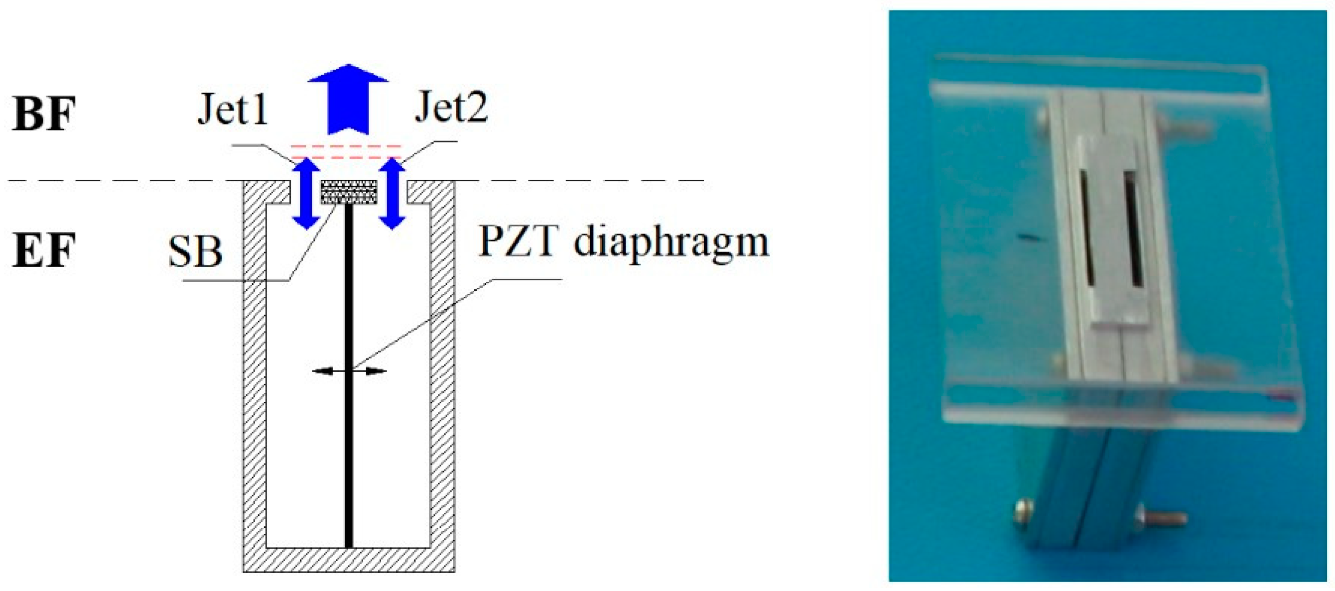
The traditional SJA, however, with one side of the PZT diaphragm exposed to the air drawn from the base flow (BF) and the other surface exposed to the environment flow (EF), will have two problems of pressure failure and inefficient energy utilization, as shown in Figure 1. The pressure loading will cause a smaller deflection of the PZT diaphragm, supporting the fact that the SJA must require a higher power to drive the PZT diaphragm when the pressure differential between the BF and the EF is large. Moreover, half of the vibrating energy of the diaphragm is wasted in the environment, meaning the energy utilization is not efficient.
A novel dual synthetic jet actuator was invented by us [18]. A schematic and a photograph of the DSJA are shown in Figure 2. The DSJA is made up of two enclosed cavities that are bounded by a single PZT diaphragm, with two emitting slots and a slide block (SB) placed in the middle of the two slots. In the evolutionary process of dual synthetic jets, two synthetic jets out of phase are forced out of the cavity in every oscillating cycle, instead of a fluid puff for every vibrating circle from a traditional SJA. Actuators with a similar physical structure driven by a loudspeaker, called twin synthetic jet actuators, have also been displayed and researched in references [19,20]. The unique merits of the DSJAs lie in the fact that the two chambers share one wall equipped with a single PZT diaphragm, and the middle slide block regulates the two synthetic jets. The two cavities sharing the same PZT diaphragm make the novel synthetic jet actuator not only double the function of the traditional SJA, but also resolves the problems of pressure failure and inefficient energy utilization of the SJA. As the diaphragm of the DSJA is completely surrounded by the fluid drawn from the BF, the DSJA avoids the high power required to drive the PZT diaphragm when the pressure differential is great. In addition, the slide block can adjust the two synthetic jets, enabling the DSJA to have a unique thrust-vectoring characteristic that the traditional SJA does not have [21,22].
To understand the detailed differences between the DSJ and the SJ, PIV technology is used to capture the basic flow field characteristics of the DSJA and the SJA, and then careful comparison between each other is implemented. In addition, the unique vectoring characteristic of the DSJA is also discussed to show the regulating ability of the middle slide block.

2. Experimental Technique

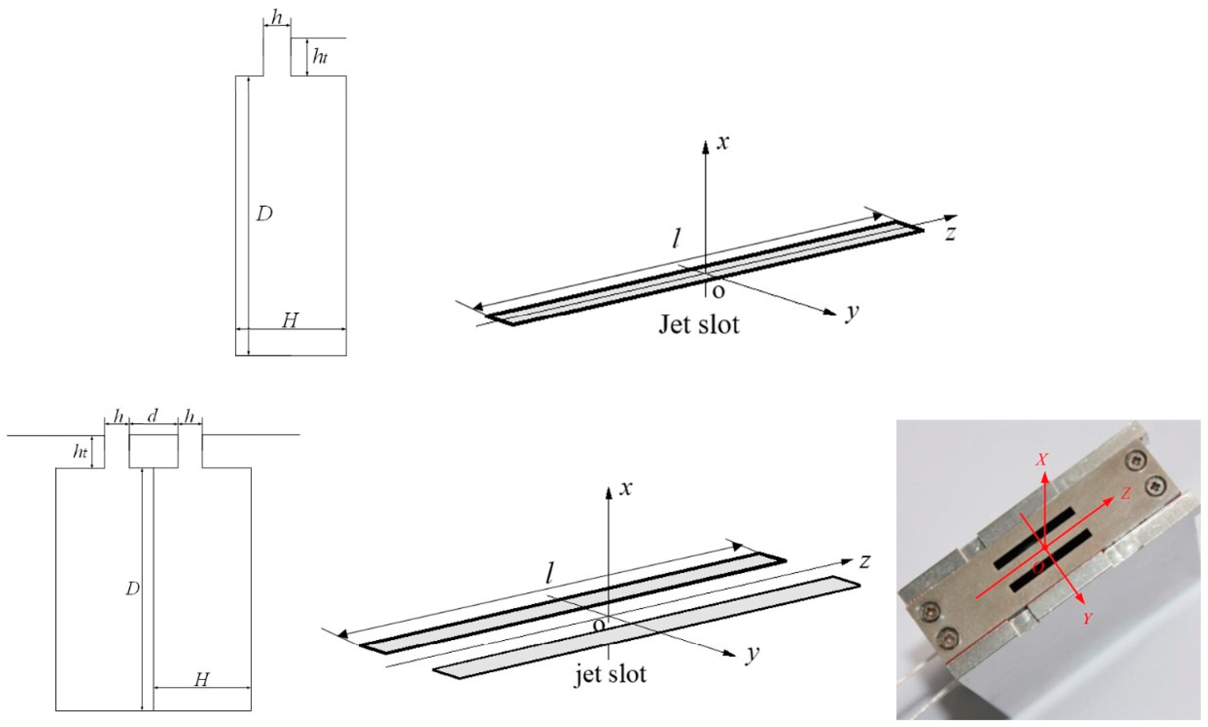
The DSJA studied in this paper is “mini” in size, and is composed of two symmetrical, cylindrical chambers (inner diameter D = 46 mm, height H = 7 mm) bounded on one end by a PZT diaphragm (thickness = 0.2 mm) and driven by an electrical signal with voltage amplitude UA of 300 V and a frequency f of 500 Hz. A rigid wall (thickness ht = 4 mm) with two symmetrical slots (length l = 20 mm, width h = 2 mm) covers the upper end, and the distance between the two slots d is equal to 5 mm. The driving frequency is equal to the diaphragm resonance frequency, which can generate a higher velocity than that actuated at the Helmholtz frequency (1196.5 Hz). Figure 3 shows the overall structures and physical models of the SJA and the DSJA. It is worth noting that the left slot of the DSJA will be sealed to turn into a SJA under the test condition of the SJA. The key parameters of both modes are exhibited in Table 1.
PIV is an ideal technique that can characterize non-periodic and quasi-periodic phenomena temporally, but accurate phase referencing is not available. For fast-varying flow fields with a fine spatial structure, traditional PIV approaches cannot capture the short time and length scales of the flow field and its temporal–spatial evolution. In practical applications, it is necessary to address issues such as the transient response of both the fluid and the structure, the energy transfer process among the different scales in transition, turbulence, and so on. Considering that the SJ has a periodic unsteady flow and phase referencing rules are available, the transfer phase and sub-frequency (TPSF) technique is applied to capture the arbitrary phase of the DSJ, and the phase of the DSJ can be determined by the transfer-phase-to-equal (TPE) technique in previous work by us [14].
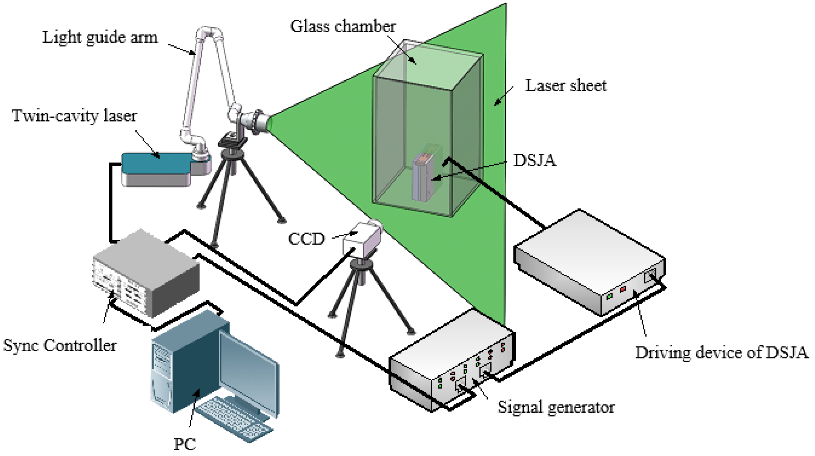
The PIV system comprises a twin-cavity laser (2 × 200 mJ), a light guide arm, a charge-coupled-device (CCD, 2456 × 2056 pixels, 12 bits) camera with a 24 mm F/2.8 lens, a narrow band-pass filter of 532 ± 5 nm, a sync controller and a PC software, as shown in Figure 4. The DSJA is fixed in a closed glass chamber with a size of 400 × 200 × 200 mm. The smoke, with an average diameter of less than 4μm, is adopted as tracer particles. A signal generator can provide two signals with the same phase and frequency. One is transmitted to the driving device of the DSJA, and the other one is provided to the sync controller as the external trigger signal, by which the locked phase measurements can be realized. The laser sheet, projected perpendicular to the slots at the midsection for x-y plane measurements, has a thickness of 0.5 mm and is employed to illuminate the two-dimensional flow fields. The sampling frequency is set at 10 Hz. The uncertainty of the tracer-particle displacement is less than 0.1 pixels. Therefore, the uncertainty of the measured velocity would be less than 0.7 m/s. A DSJ cycle is uniformly divided into 12 phase points. A PIV recording is implemented using TPSF and TPE technology, and then a phase-averaged velocity field is acquired based on 50 pairs of captured images at each phase point. Figure 3 also shows the DSJA coordinates. The flat plate containing the slots is parallel to the free surface of the water, and the jets are emitted into the fluid medium perpendicular to the plate. The camera is focused onto an area of 25 mm (horizontal) × 25 mm (vertical), with the lower border of the image coinciding with the flat plate.

3. Results and Discussion

3.1. Comparison between DSJA and SJA

The tests of a novel DSJA and a traditional SJA at the same forcing conditions and some key parameters of the SJA are listed in Table 2.
The Reynolds number (Reu) and the Strouhal number (St) of the SJ are defined as:
Re u = ρ h u a m p / μ
S t = h f / u a m p
where ρ and μ is the air density and viscosity, respectively, and uamp is the velocity amplitude of the SJ.
The stroke length L0 of the SJ and Re based on the blowing phase per unit width ReI0 were provided by Smith and Glezer as follows [6]:
L 0 = 0 T / 2 u 0 ( t ) d t
Re I 0 = I 0 / μ h ,   I h = ρ h 0 T / 2 u 0 2 ( t ) d t
where u0(t) is the instantaneous centerline velocity at the actuator slot exit and T is the time of a DSJ period. The dimensionless time t* is equal to t/T-N and T = 1/f, where N is the circles.
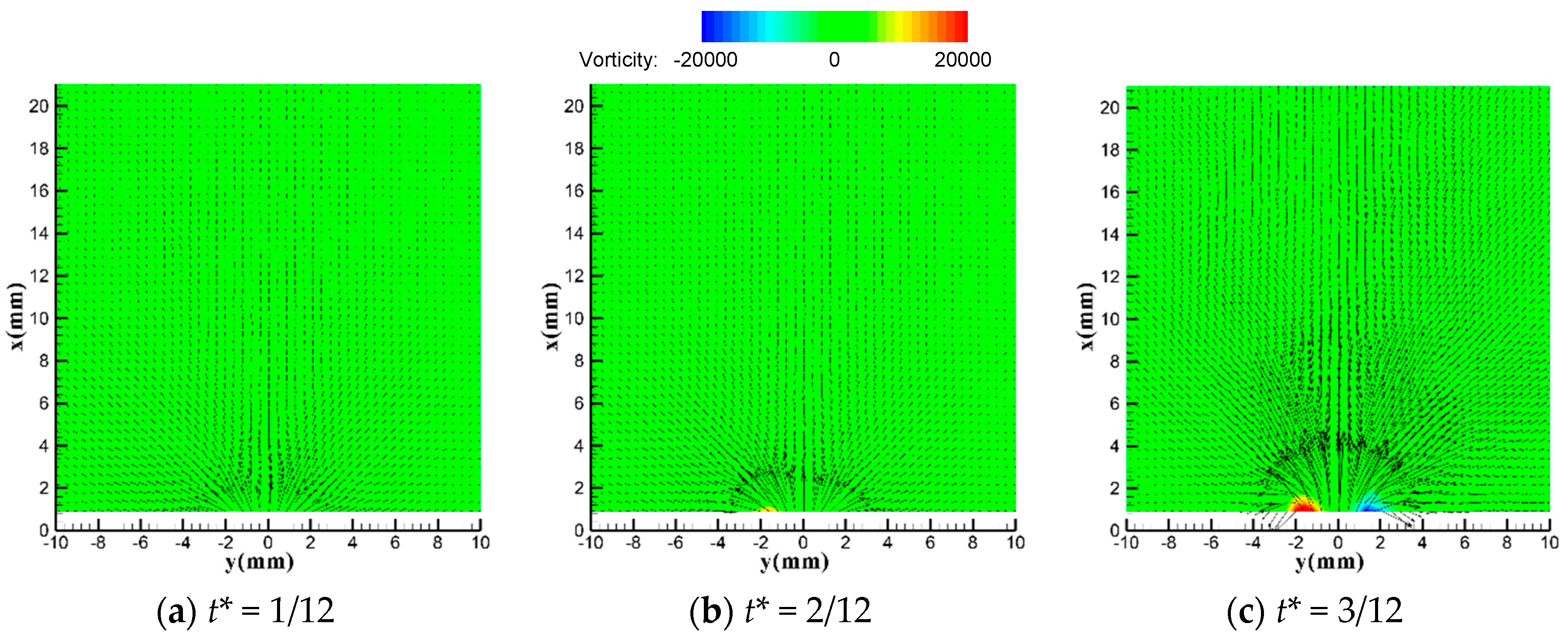
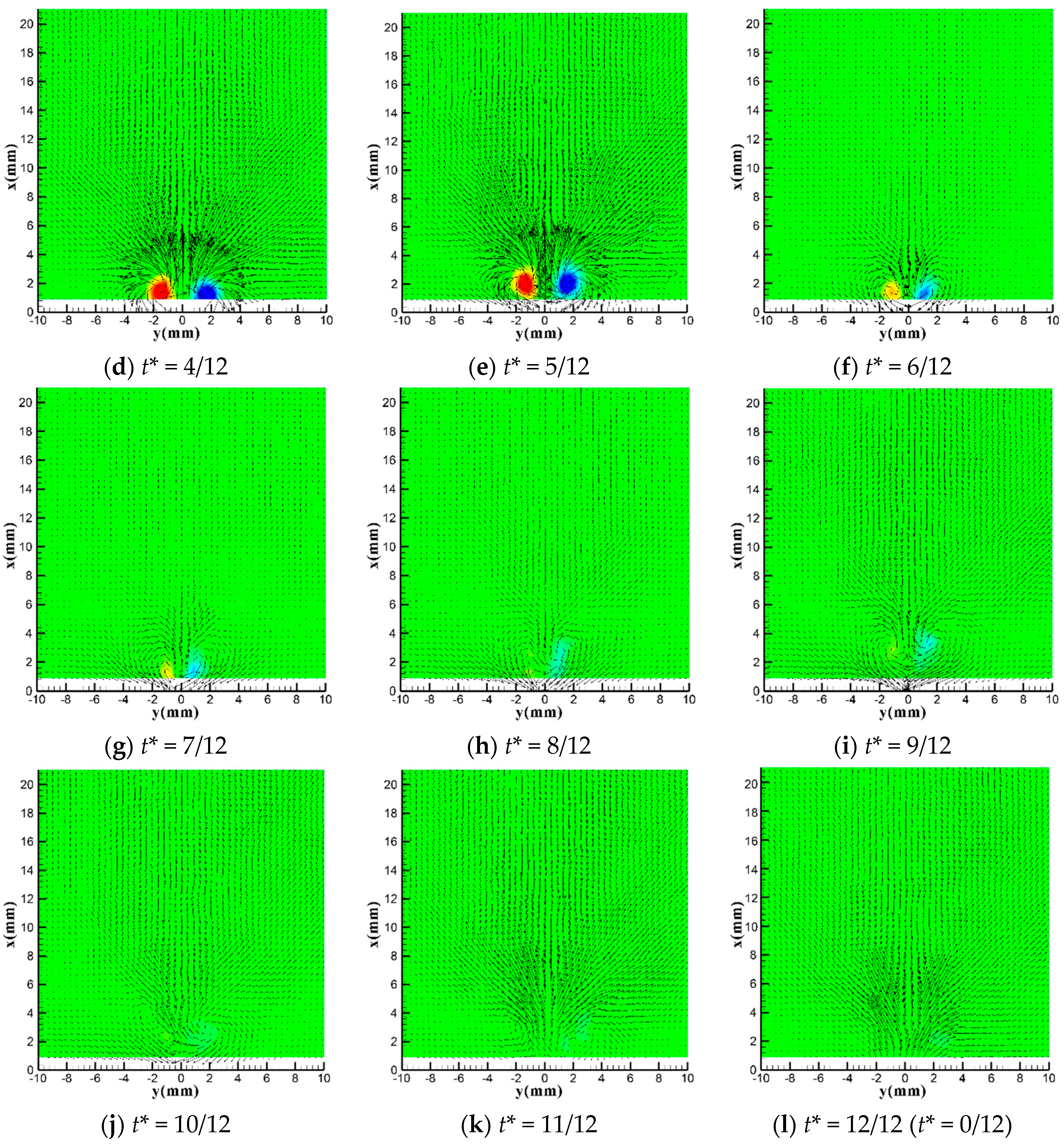
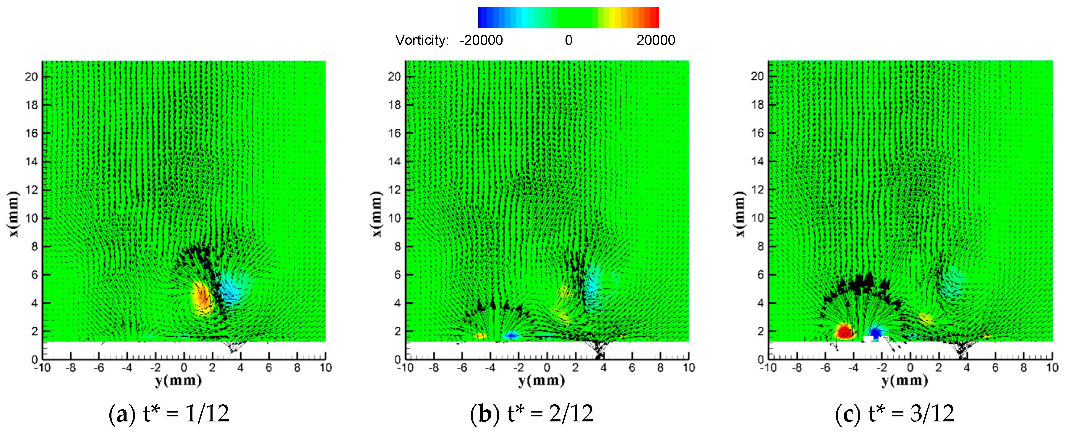
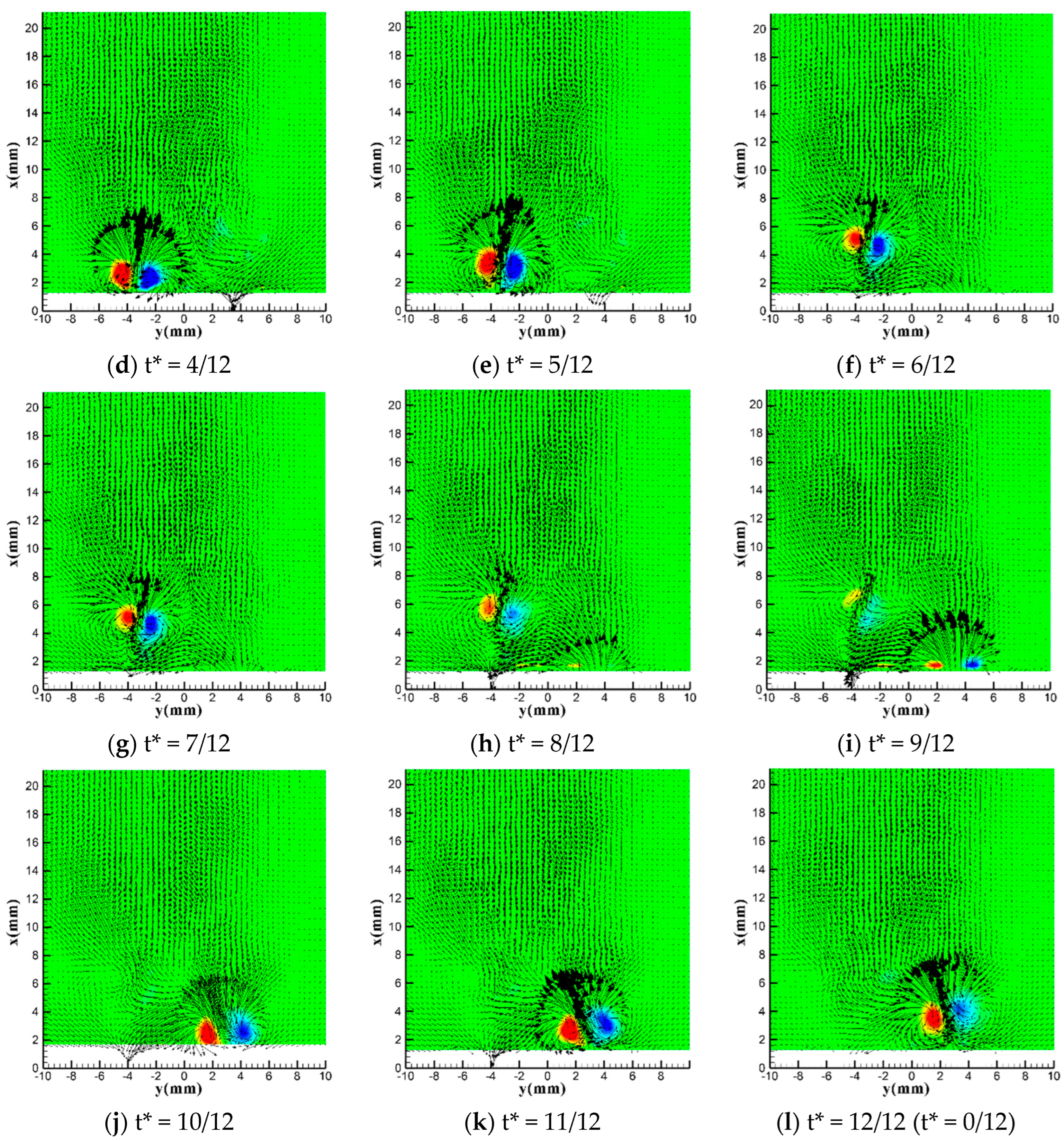
Figure 5 and Figure 6 show the flow fields of the SJA and the DSJA at a different dimensionless time in an actuating cycle. Figure 7 shows time-locked velocity traces of one cycle at six measured points ((1.5, −3.5), (1.5, 0), (1.5, 3.5), (6, 0), (10, 0), and (20, 0)), and the points (1.5, −3.5) and (1.5, 3.5) are, respectively, located on the left and right slot exit centerline of the DSJA.
Figure 5 shows the PIV measurements of the SJA for comparison. Figure 6 and Figure 7 demonstrate a cycle of the DSJ that can be divided into a “left” stage and a “right” stage. In the “left” stage, the flow field is dominated by the left jet (Jet1). Similarly, the flow field is dominated by the right jet (Jet2) in the “right” stage. This means that the time-periodic PZT diaphragm determines the flow field of the DSJ. It is worth noting that the two synthetic jets out of the phase entrain the air around them, and then interact with each other in the near-field downstream, as shown in Figure 6. When the Jet1 is in the suction stroke and the Jet2 is in the blowing stroke (Figure 6g–l), some fluid of the Jet2 is sucked into the left slot, while some fluid of the Jet1 is sucked into the right slot when Jet1 maintains the blowing stroke (Figure 6a–f), which supports that a phenomenon of “self-support” appears between the two synthetic jets. If all of the fluid of the jet is sucked into the adjacent slot, there will not be a stable jet in the far-field downstream of the DSJA. Therefore, the phenomenon of “self-support” between a pair of synthetic jets is unfavorable, which could weaken the strength of the dual synthetic jets downstream.
Figure 6 also shows the vorticity magnitude and two counter-rotating vortex pairs produced by the DSJA. The vorticity of the vortex pairs contributes to the pressure difference. An “induced” velocity V, a translation velocity with which the vortex ring travels, is given by Hill and Saffman [15] as follows:
V = Γ 2 π a [ ln 8 a ( 4 ν t ) 1 / 2 0.558 + O ( ν t a 2 ) 1 / 2 ]
where Γ is the circulation and a is the radius of the vortex ring. The vortices decelerate not only by losing energy due to friction, but also through entrainment of fluid from the environment. The circulation Γ ω and the “induced” velocity V contributes to the pressure difference. The pressure in the area of the main vortex pairs is lower than in other flow domains. The stronger the vortex ω , the stronger the circulation Γ , the higher the velocity V, and the lower the pressure will get. Equation (5) also shows that the velocity V is strongly associated with the time t, indicating that the phase angle also contributes to the “induced” velocity V and the pressure difference. The results show that in the far field downstream, the fore vortex pairs entrain the aft vortex pairs, and the aft vortex pairs are deflected to the fore vortex pairs due to the lower pressure. Meanwhile, the fore vortex pairs will decelerate gradually by losing energy due to friction and entrainment of fluid from the environment, and the aft vortex pairs will also impact the fore vortex pairs. Lastly, a single, more stable synthetic jet could be realized by the merging of the two synthetic jets. Figure 7 also indicates that the two jets of the DSJA could merge into a single, more stable synthetic jet in the far field. Furthermore, Figure 7b,c shows that the DSJ downstream has a double characteristic frequency, which broadens the applying frequency domain.
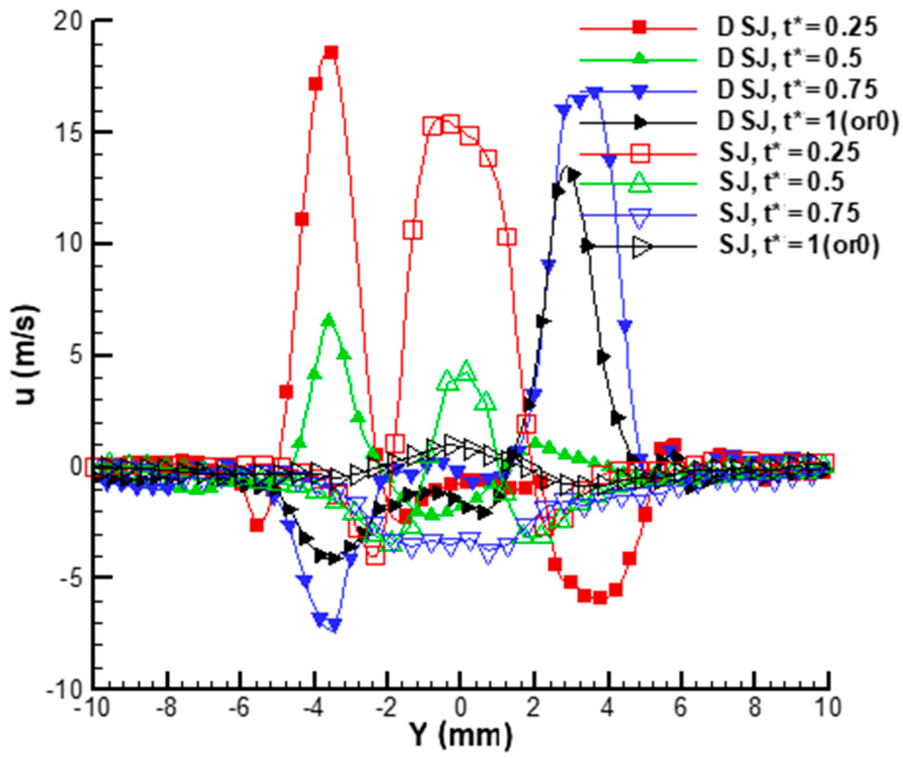
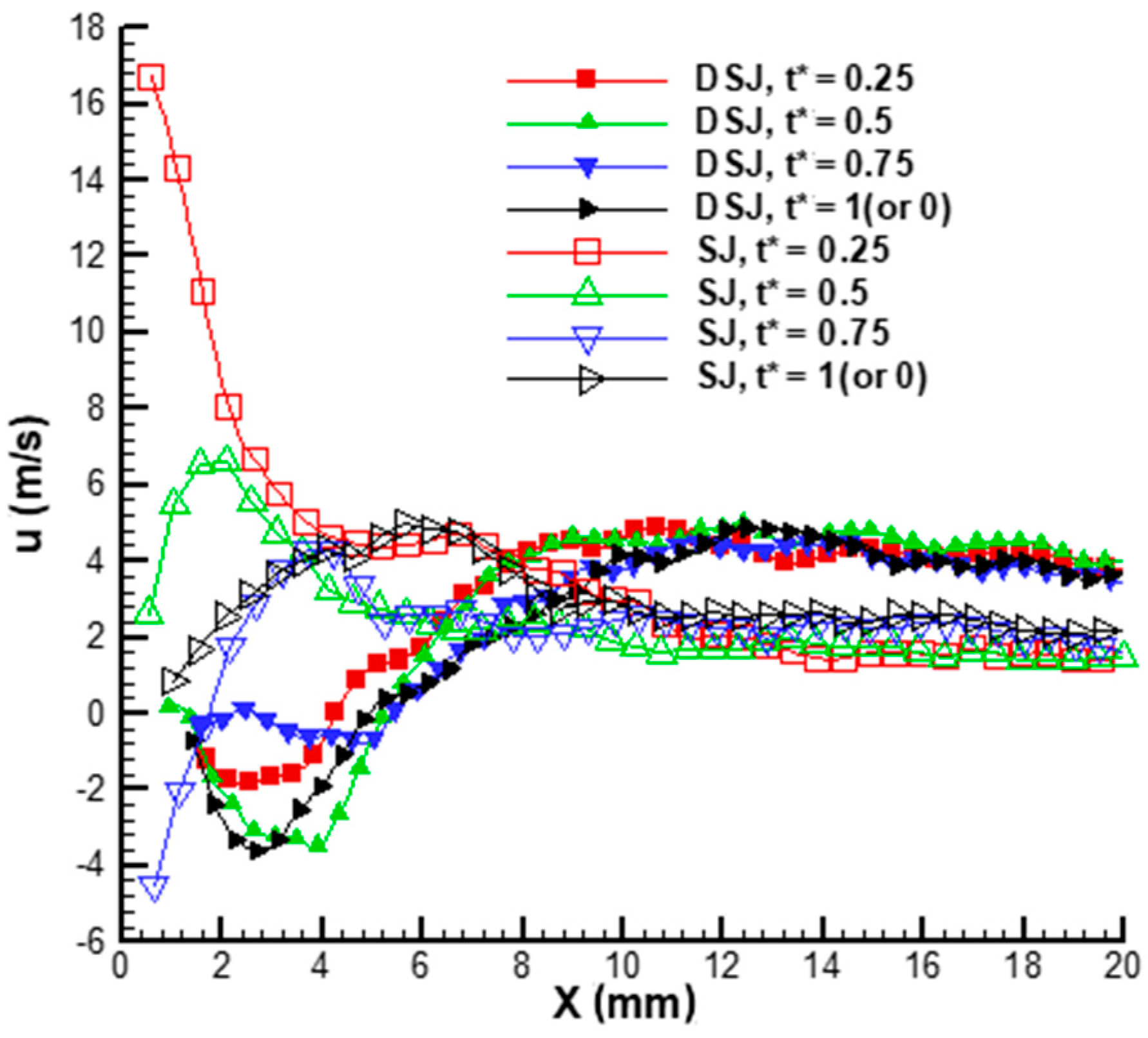
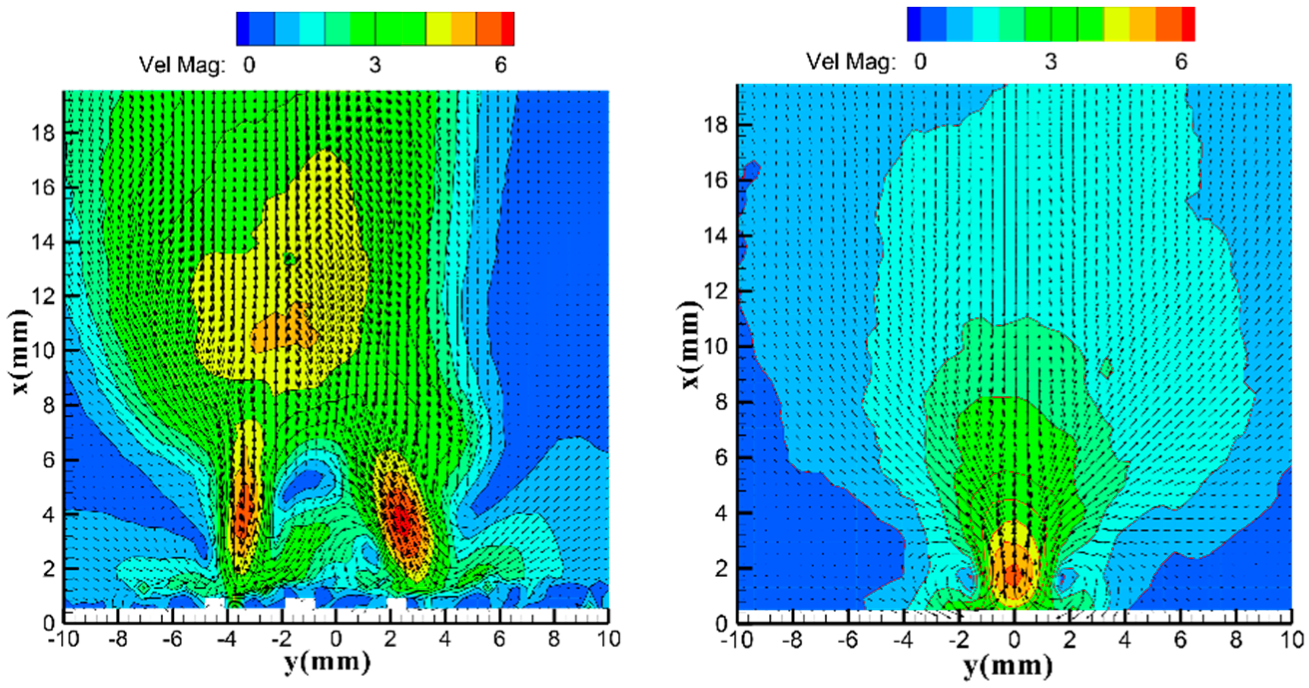
The detailed comparisons between the DSJ and the SJ are shown in Figure 8, Figure 9 and Figure 10. In the near-field downstream, the flow fields controlled by the DSJ and the SJ similarly emerge into four stages (accelerating blow, decelerating blow, accelerating suction and decelerating suction), while the flow characteristic of the DSJ is more complex than that of the SJ. Moreover, the blowing or sucking peak velocity of the DSJ is larger, showing a higher control ability. It is worth noting that in the mode of the DSJ, the left peak velocity is slightly lower than the peak velocity of the right exit, which may result from the preload differences of both sides. Considering that the PZT diaphragm is fixed by bolts, the clamping conditions on both sides of the diaphragm may be different, resulting in the inconsistent vibrating amplitude in both directions of the PZT diaphragm, thus showing the different velocity evolution. Furthermore, the two synthetic jets of the DSJ could merge into a single, more stable jet with a higher velocity in the far field downstream.
Based on the above analysis, the structure of the two cavities sharing a single diaphragm ensures that the DSJA not only has the unique property of zero mass flux, but also solves the problems of pressure failure and inefficient energy utilization existing in a traditional SJA, which extends the applications of the DSJA to more flow control systems, such as thrust vectoring control and flight control [23,24].

3.2. Special Vectoring Characteristics of DSJA

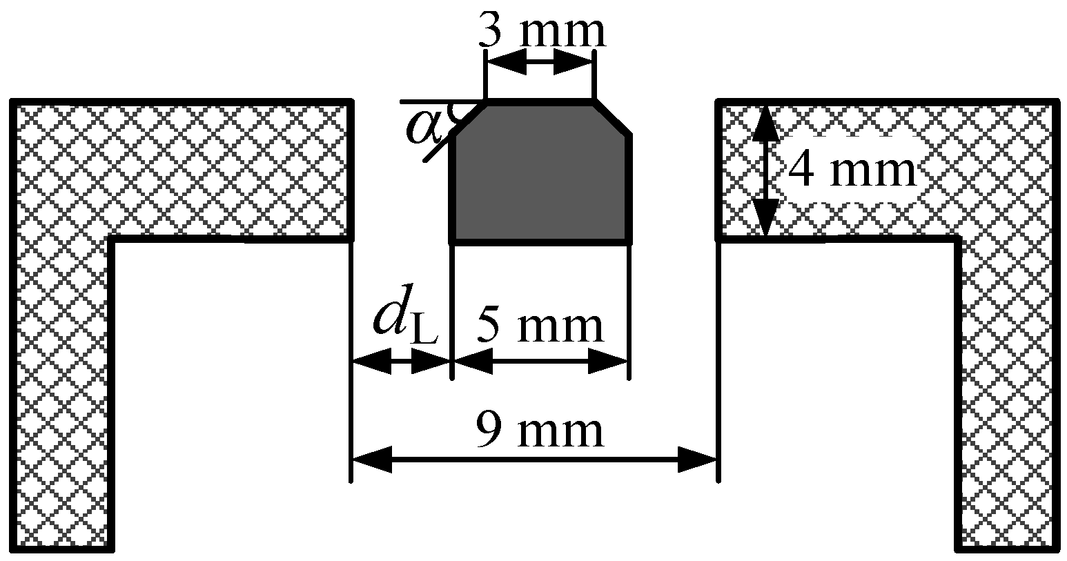
The slide block between the two slots can regulate the two synthetic jets by removing it left or right, making the DSJA have a unique vectoring characteristic. The DSJ are formed by the fusion of two SJs, and the momentum ratio and low-pressure zone strength of the two jets can be modulated by changing the area ratio of two slots, which indicates the vectoring deflection of the DSJ. The low-pressure zone and the inertia of the two SJs are the key parameters that demonstrate the vectoring deflection angle (VDA) of the DSJA [20]. Furthermore, it is the structure of the middle slide block that also determines the area and strength of the low-pressure zone, playing an important role in the vectoring characteristics. Based on the method proposed by Deng [19] to calculate the VDA, the PIV measurements have been carried out to show the vectoring characteristic of the DSJA, with different slot area ratios and changed structures of the slide block. The structure schematic of the slide block is shown in Figure 11, where the exit chamfer α and the length of the left exit dL are variable. In detail, α could be changed from 0° to 60° by transforming the slide block, and dL can be shifted from 0.4 mm to 3.6 mm with an interval of 0.4 mm. Additionally, the driving voltage (±250 V) and the frequency (550 Hz) are maintained constantly in this research.
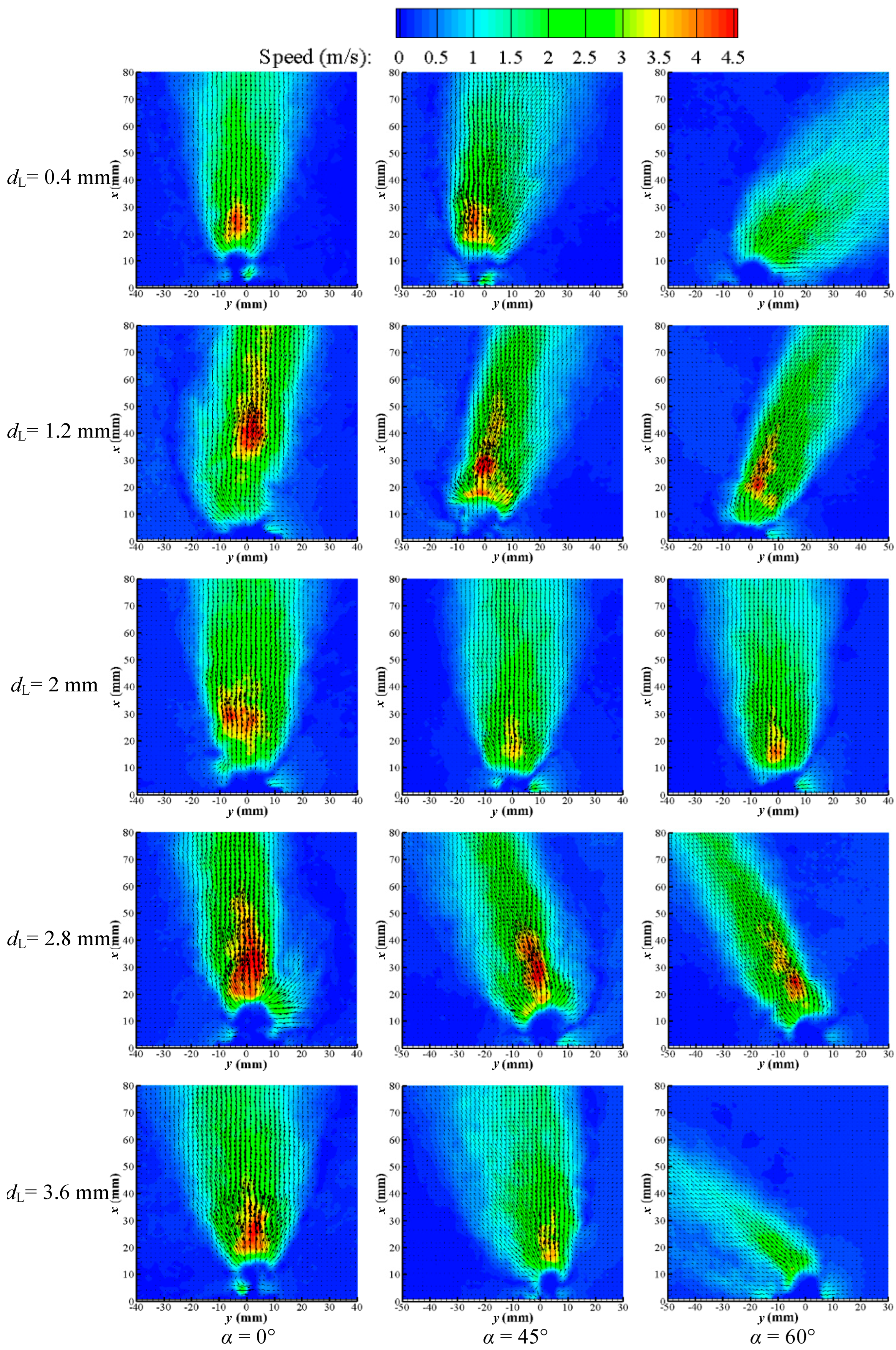
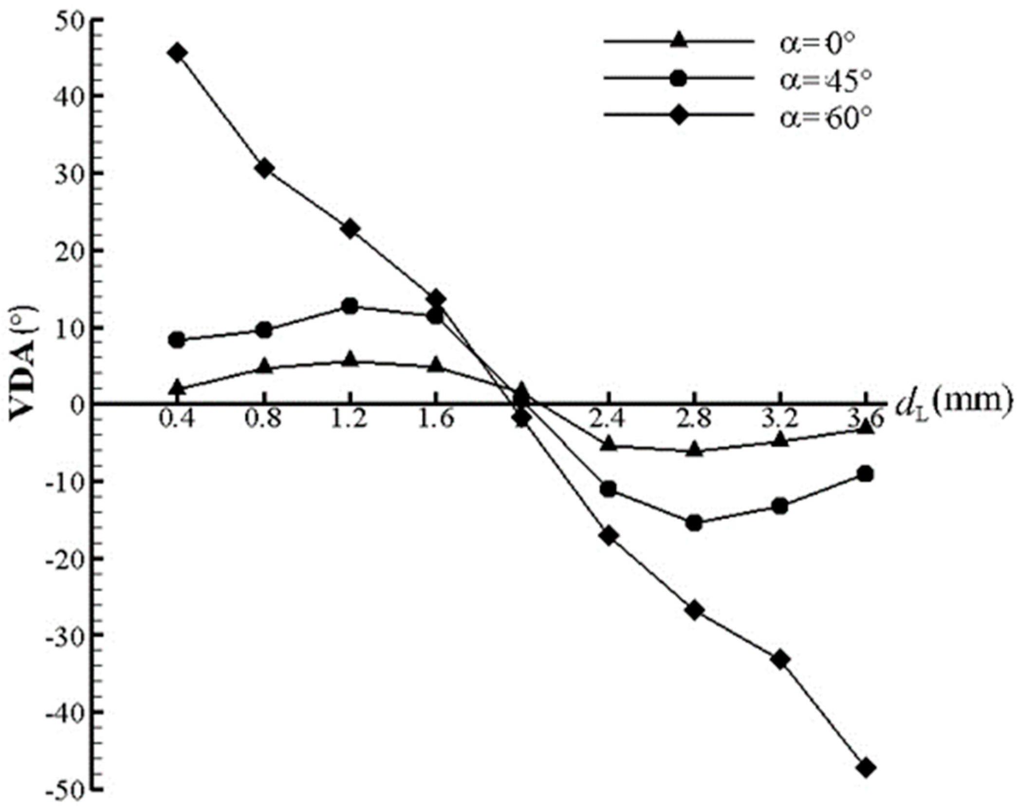
The PIV test results have been shown in Figure 12, suggesting that the DSJ can deflect to the wider exit and the VDA increases gradually with the augmentation of α for the same dL. In addition, Figure 13 shows the VDA of the DSJ under different α and dL, obviously indicating that for a different α, the VDA basically presents an antisymmetric change relative to the point of dL = 2 mm. When α = 0° or 45°, the VDA increases first and then decreases on the single side, and the extreme values are obtained when dL = 1.2 mm and 2.8 mm, while when α = 60°, the VDA keeps decreasing. The bigger the α, the larger the VDA, which is consistent with the change trend of the PIV results. The larger α could generate a stronger Coanda effect, making the jet with a shorter exit width deflect to a greater angle, thus realizing a bigger VDA, although the jet with a larger exit could suppress the deflection. Due to the positioning error of the slide block, the two outlets are not completely symmetrical when dL = 2 mm, resulting in a certain deviation between the VDA and the theoretical value (0°). It is worth noting that when α = 60°, the VDA shows a linear relationship with the increase in dL, and the approximate variation range of the VDA (−46°~46°) is wider, which is more conducive to the design and optimization of the active flow control law.

4. Conclusions

To understand the detailed discrepancy between the DSJ and the SJ in quiescent surroundings, a novel DSJA was investigated using PIV, and its flow-field characteristics were compared with the traditional SJA. A transfer-phase and sub-frequency technique was introduced to capture the arbitrary phase of the DSJ, and a transfer-phase-to-equal technique was provided to determine the phase of the DSJ. In addition, the unique vectoring characteristics of the DSJA with a variable α and dL were also explored.
The results indicate that a cycle of the DSJ can be divided into a “left” stage and a “right” stage. In the “left” stage, the flow field is dominated by the left jet, while the flow field is dominated by the right jet in the “right” stage. In the near-field downstream of the DSJA, the two jets entrain air around them and interact with each other, and the flow field is more complex than that of the SJA. There is an unfavorable phenomenon of “self-support” between the two synthetic jets, weakening the strength of the DSJ downstream. In the-far field downstream of the DSJA, the two vortex pairs interact with each other and entrain fluid from the surroundings, and the DSJs merge into a single, more stable synthetic jet (similar to a steady jet) with a higher velocity and a double characteristic frequency. In addition, the DSJA has shown great vectoring characteristics, with the VDA changing from approximately −46° to 46°, suggesting a broader applying prospect. These results indicate that the traditional SJA may be replaced by the DSJA in many applications, and the applying area of the synthetic jets could be extended to more active flow control systems that cannot be qualified by the traditional SJA.
In this paper, the comparison of the DSJ and the SJ in quiescent environments is explored, but its evolution process under the condition of incoming flow was not shown, which may have more engineering significance. Therefore, further work will focus on the comparison of the evolution process with the incoming flow, and wing tunnel tests will also be implemented.

Author Contributions

Conceptualization, Z.L. and Z.X.; methodology, Z.Z. and L.W.; formal analysis, Z.Z. and Z.L.; writing—original draft preparation, X.D. and Z.Z.; writing—review and editing, Z.L. and Z.Z. All authors have read and agreed to the published version of the manuscript.

Funding

The authors are grateful to the National Nature Science Foundation of China for its financial support for this project (Grants: U2141252, 11972369, 11872374).

Conflicts of Interest

The authors declare no conflict of interest.

Nomenclature

DDiameter of cylindrical chambers
HHeight of cylindrical chambers
UADriving voltage amplitude
fDriving frequency
htThickness of rigid wall
lLength of slots
hWidth of slots
dDistance between the two slots
ReuReynolds number based on jet exit
StStrouhal number
wVorticity
αExit chamfer
ρ Air density
μ Air viscosity
uampVelocity amplitude of SJ
L0Stroke length of SJ
ReI0Re based on the blowing phase per unit width
u0(t)Instantaneous centerline velocity at the actuator slot exit
TTime of a DSJ period
t*Dimensionless time
V“Induced” velocity
Γ Circulation
aRadius of the vortex ring
dLLength of left exit

References

  1. Glezer, A.; Amitay, M. Synthetic jets. Annu. Rev. Fluid Mech. 2002, 34, 503–529. [Google Scholar] [CrossRef]
  2. Luo, Z.B.; Xia, Z.X. Advances in synthetic jet technology and applications in flow control. Adv. Mech. 2005, 35, 221–234. (In Chinese) [Google Scholar]
  3. Zhang, P.F.; Wang, J.J.; Feng, L.H. Review of zero-net-mass-flux jet and its application in separation flow control. Sci. China Ser. E Technol. Sci. 2008, 51, 1315–1344. [Google Scholar] [CrossRef]
  4. Wen, X.; Tang, H.; Liu, Y.Z. Interaction of twin synthetic jets in attached and separated boundary layers: Effects of yaw angle and phase difference. J. Vis. 2018, 21, 949–963. [Google Scholar] [CrossRef]
  5. Wen, X.; Tang, H.; Duan, F. Interaction of in-line twin synthetic jets with a separated flow. Phys. Fluids 2016, 28, 043602. [Google Scholar] [CrossRef]
  6. Smith, B.L.; Glezer, A. The formation and evolution of synthetic jets. Phys. Fluids 1998, 10, 2281–2297. [Google Scholar] [CrossRef]
  7. Singh, P.K.; Renganathan, M.; Yadav, H.; Sahu, S.K.; Upadhyay, P.K.; Agrawal, A. An experimental investigation of the flow-field and thermal characteristics of synthetic jet impingement with different waveforms. Int. J. Heat Mass Transf. 2022, 187, 122534. [Google Scholar] [CrossRef]
  8. Kim, M.; Essel, E.E.; Sullivan, P.E. Effect of varying frequency of a synthetic jet on flow separation over an airfoil. Phys. Fluids 2022, 34, 015122. [Google Scholar] [CrossRef]
  9. Xu, X.P.; Zhou, Z. Analytical study on the synthetic jet control of asymmetric flow field of flying wing unmanned aerial vehicle. Aerosp. Sci. Technol. 2016, 56, 90–99. [Google Scholar] [CrossRef]
  10. Trávnícek, Z.; Tesar, V. Annular synthetic jet used for impinging flow mass-transfer. Int. J. Heat Mass Transf. 2003, 46, 3291–3297. [Google Scholar] [CrossRef] [Green Version]
  11. Pitital, I.; Rajnish, N.S. Large Eddy simulation of a NACA0015 circulation control airfoil using synthetic jets. Aerosp. Sci. Technol. 2018, 82–83, 545–556. [Google Scholar]
  12. Wen, X.; Tang, H.; Duan, F. Vortex dynamics of in-line twin synthetic jets in a laminar boundary layer. Phys. Fluids 2015, 27, 083601. [Google Scholar] [CrossRef] [Green Version]
  13. Rice, T.T.; Amitay, M. Forced Flow Reattachment Process and the Effect of Pressure Gradient. AIAA J. 2019, 57, 2795–2807. [Google Scholar] [CrossRef]
  14. Xia, H.; Qin, N. Detached-eddy simulation for synthetic jets with moving boundaries. Mod. Phys. Lett. B 2005, 28, 1429–1434. [Google Scholar] [CrossRef]
  15. Hill, D.J.; Saffman, P.G. Counter-rotating vortex patches in shear: A model of the effect of wind shear on aircraft trailing vortices. Proc. R. Soc. Lond. A 2002, 458, 1527–1553. [Google Scholar] [CrossRef]
  16. Wang, Q.T.; Cheng, K.M.; Gu, Y.S.; Li, Z.Q. Continuous control of asymmetric forebody vortices in a bi-stable state. Phys. Fluids 2018, 30, 024102. [Google Scholar] [CrossRef]
  17. Zhao, G.Q.; Zhao, Q.J.; Gu, Y.S.; Chen, X. Experimental investigations for parametric effects of dual synthetic jets on delaying stall of a thick airfoil. Chin. J. Aeronaut. 2016, 29, 346–357. [Google Scholar] [CrossRef] [Green Version]
  18. Luo, Z.B.; Xia, Z.X.; Liu, B. New generation of synthetic jet actuators. AIAA J. 2006, 44, 2418–2420. [Google Scholar] [CrossRef]
  19. Crispo, C.M.; Greco, C.S.; Cardone, G. Convective heat transfer in circular and chevron impinging synthetic jets. Int. J. Heat Mass Transf. 2018, 126, 969–979. [Google Scholar] [CrossRef]
  20. Greco, C.S.; Ianiro, A.; Imbriale, M.; Astarita, T.; Cardone, G. PIV Measurements in Twin Synthetic Jets. In Proceedings of the 15th International Symposium on Flow Visualization, Minsk, Belarus, 25–28 June 2012. [Google Scholar]
  21. Deng, X.; Xia, Z.X.; Luo, Z.B.; Li, Y.J. Vector-adjusting characteristic of dual-synthetic-jet actuator. AIAA J. 2015, 53, 794–797. [Google Scholar] [CrossRef]
  22. Zhao, Z.J.; Luo, Z.B.; Deng, X.; Liu, Z.; Li, S. Theoretical modeling of vectoring dual synthetic jet based on regression analysis. Chin. J. Aeronaut. 2021, 34, 1–12. [Google Scholar] [CrossRef]
  23. Luo, Z.B.; Xia, Z.X. Jet vectoring using a novel synthetic jet actuator. Chin. J. Aeronaut. 2007, 20, 193–201. [Google Scholar] [CrossRef] [Green Version]
  24. Luo, Z.B.; Zhao, Z.J.; Liu, J.F.; Deng, X.; Zheng, M.; Yang, H.; Chen, Q.; Li, S. Novel roll effector based on zero-mass-flux dual synthetic jets and its flight test. Chin. J. Aeronaut. 2022, 35, 1–5. [Google Scholar] [CrossRef]
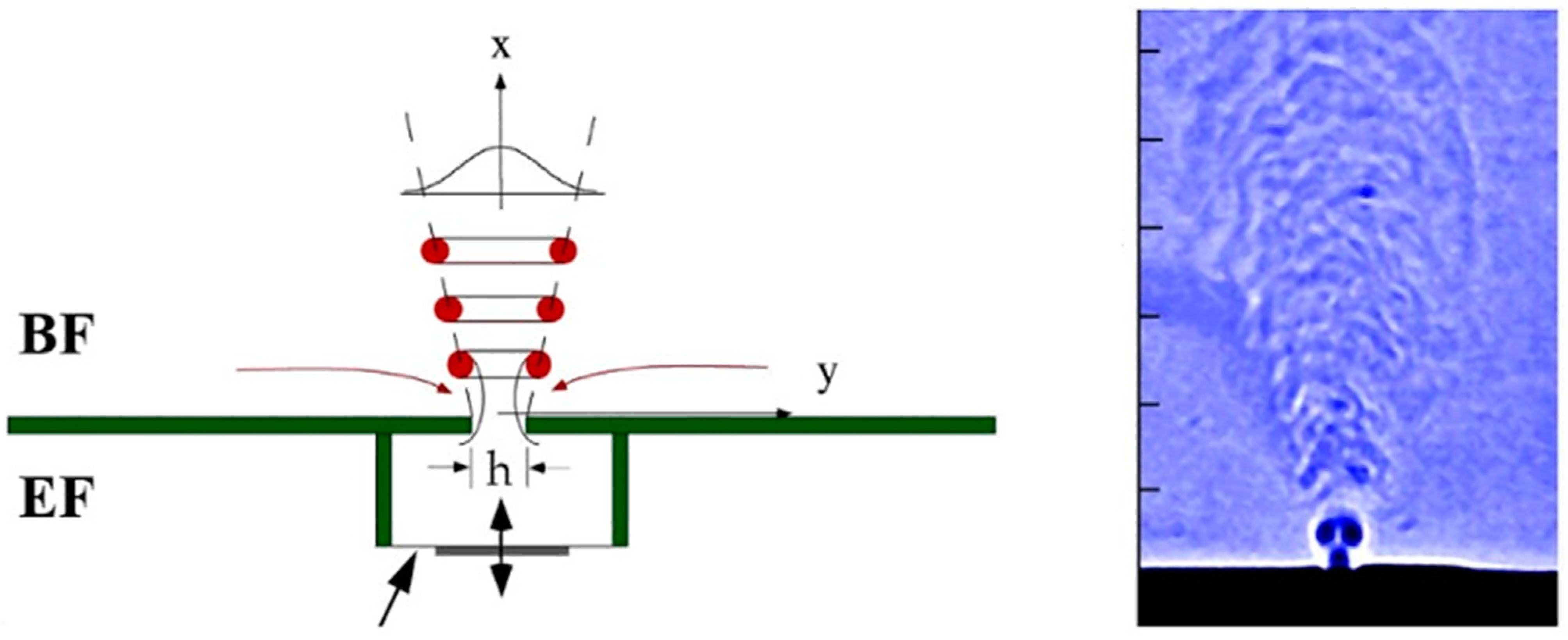
Figure 1. Schematic of a traditional SJA and schlieren flow visualization. The two surfaces of the diaphragm are exposed to the BF and EF, respectively [6].
Actuators 11 00205 g001
Figure 2. Schematic and photograph of a novel DSJA. The two cavities share the same PZT diaphragm, and the diaphragm is only surrounded by the fluid drawn from the BF [18].
Actuators 11 00205 g002
Figure 3. Structure diagram of SJA and DSJA.
Actuators 11 00205 g003
Figure 4. Diagram of PIV system.
Actuators 11 00205 g004
Figure 5. PIV measurements of the SJA.
Actuators 11 00205 g005aActuators 11 00205 g005b
Figure 6. PIV measurements of the DSJA.
Actuators 11 00205 g006aActuators 11 00205 g006b
Figure 7. Time-locked velocity traces on six measured points per unit circle.
Actuators 11 00205 g007
Figure 8. Streamline velocity of DSJ and SJ on x = 1 mm at different times.
Actuators 11 00205 g008
Figure 9. Streamline velocity of DSJ and SJ on y = 0 at different times.
Actuators 11 00205 g009
Figure 10. Mean velocity of DSJ (left) and SJ (right).
Actuators 11 00205 g010
Figure 11. Structure schematic of slide block.
Actuators 11 00205 g011
Figure 12. PIV measurements of DSJA with different α and dL.
Actuators 11 00205 g012
Figure 13. VDA measurements of DSJA with different α and dL.
Actuators 11 00205 g013
Table 1. Geometry and electrical parameters of SJA and DSJA.
TestActuatorSlotsCaviesElectrical Current
l/mmh/mmd/mmD/mmH/mmUA/Vf/HzWave Form
T1SJA202467300500rectangular
T2DSJA2025467300500rectangular
Table 2. Key parameters: Comparison of a novel DSJA and a traditional SJA.
TestActuatorUA/Vf/Hzuamp/(m/s)ReuReIoStL0/mm
T1SJA30050016.5220095000.1910.5
T2DSJA30050018.5250012,0000.1711.8
Publisher’s Note: MDPI stays neutral with regard to jurisdictional claims in published maps and institutional affiliations.