Abstract
A novel fluidic thrust-vectoring (FTV) control method based on dual synthetic jets actuator (DSJA) is proposed and evaluated. Numerical simulations are governed by the compressible Unsteady Reynolds-Averaged Navier–Stokes (URANS) equations. According to the results, DSJA is capable of deflecting a primary jet with a velocity of 100 m/s and a height of 50 mm by approximately 18 degrees with a momentum coefficient of 1.96%. It produces comparatively linear control characteristics in almost all deflection angles evaluated (0~23 degrees). The low pressure generated by DSJA, the ejecting enhanced by DSJA, and the co-flow effect produced by the accelerated secondary jet all play roles in the deflection of the primary jet. Since the primary jet is strong enough, the potential of DSJA to provide thrust vector control is revealed.
1. Introduction
Fluidic thrust-vectoring (FTV) technology is a kind of thrust-vectoring technology developed to control the direction of thrust without using the conventional moving surfaces, so as to reduce the structural complexity, weight, and volume, and maintaining the cost of the thrust vector control nozzle. Numerous researchers have investigated the use of FTV systems for aircraft control, and many FTV methods have been developed.
Until now, the most researched idea is to change the flow state in nozzles through the proper set of high-speed secondary jets (or suction) with designed nozzle shape, such as the shock-vector control method [1], throat-shifting method [2], dual-throat method [3] and counterflow method [4]. The co-flow method has been investigated and verified by experiments to control the subsonic and supersonic primary jets [5,6]. The co-flow method has been proven capable of realizing flight control by the flight test of MAGMA aircraft [7]. However, this method requires a high-pressure air source. Carrying an air supply would result in the massive occupation of fuselage space and weight. A high-pressure air source could also be supplied from power plant bleeding, leading to an impact on the condition of the engine. The mass of MAGMA aircraft’s flow control module occupies 40% of the total system [7] (providing circle control and FTV control). The pressure supply and the supporting pipeline system cause a large space and weight burden for aircraft.
Wen [8] strengthened the co-flow FTV control method by upgrading the secondary co-flow from a conventional steady jet to a sweeping jet. The sweeping jet was found to be more capable of enhancing the flow mixing than the steady jet, which leads to a higher efficiency in co-flow vectoring control. Using a sweeping jet greatly reduces the mass flow rate of the secondary jet to provide thrust vector control, and hopefully will alleviate the burden brought by a high-pressure gas source to a certain extent.
A bypass dual-throat nozzle [9] is developed from conventional dual-throat methods. This introduces secondary flows from a bypass set between the upstream minimum area and the upstream convergent section instead of air supply. This improvement reduces the layout difficulty of using a dual-throat vectoring nozzle and achieves an equivalent or even better performance than the conventional dual-throat vectoring nozzle. In this study, the realizable turbulent model with the standard wall function is selected.
Meanwhile, predecessors have developed some FTV methods with no dependence on air source, called passive FTV methods. Using an ejecting-mixing fluidic vectoring nozzle [10,11] takes advantage of the entrainment effect of the primary jet on the surrounding air. In detail, the deflection angle of the primary jet could be controlled by adjusting the mass rate of the entrainment secondary jet through the control valves. The results of a supersonic primary jet numerical simulation [10], a flight test powered by electric duct fan [12], and a 6 kg turbojet engine ground experiment [13] show that this method is suitable to control the direction of subsonic and supersonic primary jets.
As one of the lightest active-flow control means, synthetic jet (SJ) actuators have been widely applied in many fields, such as separation control [14], vortex-induced vibration control [15], and flight control [16]. Researchers have found that with the help of zero-mass-flux synthetic jets, the direction of the primary jet can be deflected even without any moving components. SJ actuators can be driven by piezoelectric (PZT) diaphragms or electrodes fixed in a cavity, capable of switching work state rapidly in response to different electrical signals.
Smith [17,18] found that a synthetic jet actuator installed close to the primary jet outlet could deflect the primary jet with a low momentum coefficient. However, the deflection becomes undetectable when the velocity of the primary jet increases to 30 m/s. Pack [19] carried out an experimental study with a diffuser attached to the jet exit, and the excitation was introduced at the junction between the jet exit and the diffuser inlet, demonstrating that the presence of the wide-angle diffuser increases the effectiveness of the added periodic momentum caused by a favorable interaction among the excitation, the jet shear layer, and the diffuser wall. However, Pack [19] and Chiekh [20] found that the direct deployment of the diffuser wall will lead to no-control primary flow into a bistable situation, which is intolerable in an FTV system as it will result in an unstable control moment.
The PZT diaphragm on the conventional SJ actuators is set between different pressure conditions of basic flow (the flow field to be controlled) and environment flow (usually the equipment cabin), which indicates that half of the radiation energy of the vibrating diaphragm is injected into somewhere unwanted. It also means that the PZT must overcome the pressure difference on two sides of the diaphragm to vibrate. When the pressure differential is large, the driving vibration will be difficult or even unachievable. In short, the structural design of conventional PZT-driven SJ actuators limits their energy efficiency and environmental adaptability. Subsequently, Luo [21] invented a new-generation synthetic jet actuator, known as a dual synthetic jet actuator (DSJA). Different from conventional SJ actuators, DSJ actuators have two cavities on both sides of the PZT diaphragm. Both cavities are connected to the controlled flow field, which guarantees that the pressure difference between the two sides of the PZT diaphragm will not be too large. Therefore, the energy efficiency and environmental adaptability of DSJ actuators are improved. Moreover, DSJ actuators have greater flexibility and stronger control ability. For example, DSJ could perform both functions of “push” and “pull” to vector a primary jet [22]. However, according to the latest explorations, DSJ actuators or SJ actuators are only capable of deflecting a primary jet with low velocity and small height.
To sum up, plenty of significant studies have investigated the feasibility of synthetic jet application to FTV. As a control method without introducing an air source, FTV by DSJ is a technology worthy of further in-depth research and development. However, existing studies have shown that the simple deployment of DSJ is insufficient to provide effective FTV control. This work explores the potential of dual synthetic jets for thrust vector control by proposing a novel method and its configuration.
2. Materials and Methods
2.1. Method and Configuration
The configuration of this novel FTV method is shown in Figure 1. The new method was created from the reference and improvement of existing DSJ actuators jet-deflecting method and co-flow FTV nozzle. The height of the primary jet inlet is 50 mm. Avoiding the problems of pressure loading and energy inefficiency, DSJ actuators were selected (comparing to SJ actuators) as the provider of zero-mass jet to adapt to the changing external environment in flight. In this configuration, the DSJ actuators are installed on the edge of the primary nozzle outlet, with a total thickness of 10 mm. To prevent the unexpected deflection from damaging the practicability of the nozzle, passive secondary jet inlets are arranged as gaps between the primary jet inlet wall and the nozzle wall. The gaps are connected to the outside atmosphere and are approximately 8 mm high at the downstream edge. The exits of DSJ actuators are arranged at the two downstream corners of the edge and are set 45 degrees up and down from the mainstream direction, respectively.
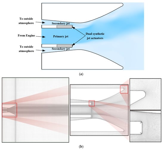
Figure 1.
Configuration design (a) and numerical calculation mesh configuration (b).
2.2. Simulation Setup
To explore flow details in nozzles and the control mechanism, 2D-simulations were applied by ANSYS Fluent. The flow is governed by the compressible Unsteady Reynolds-Averaged Navier–Stokes equations (URANS):
where the density is defined by the ideal gas equation:
and the molecular viscosity is assumed to be constant. In addition, the gravity effect is neglected.
Considering the complex flow conditions such as separation, attachment, and vortex, the realizable turbulent model (RKE) is selected to model the Reynolds stresses . This model is also applied in the studies conducted by Gu [9], in which the turbulent viscosity is calculated by using an improved method. The exact transport equation of the fluctuating component vorticity is used to derive the dissipation rate equation.
Non-Equilibrium Wall Function is used to compute complex flows such as separation, reattachment, and impact near the wall. It further extends the applicability of the wall function approach by including the effects of pressure gradient and is found to accurately predict the reattachment length, skin friction, and static pressure coefficient with the RKE model [23].
Semi-Implicit Method for Pressure-Linked Equation (SIMPLE) is used in the coupling of velocity and pressure. The spatial discretization is second order for pressure and second order upwind for density, momentum, and energy.
The configuration of mesh and boundary conditions are shown in Figure 1. Wall y+ is approximately 1. No slip wall is applied for the nozzle and actuators’ wall, pressure inlet for the primary jet, or passive secondary jet. As to environment, pressure inlet is applied for upstream boundaries, and pressure outlet for the side and downstream boundaries.
The initial condition is the transient simulation result of the baseline condition (where the primary jet is present alone and dual synthetic jets are off). All the flow field results shown were captured at the time when dual synthetic jets present for 0.1 s on the baseline of the initial condition. Applied first-order implicit time-integration schemes were used for temporal discretization. A timestep of 5 × 10⁻⁵ s (1/40 of the DSJ driving cycle) was applied for all transient simulations. The maximum iteration of each timestep is 50 and the convergence criterion is 1 × 10⁻⁶ for continuity and energy. In addition, DSJ exits were set as velocity inlet boundaries to simulate the periodic jets. Referring to the driven model of synthetic jets [24], the velocity is defined by the UDF formula shown as follows:
where is the peak velocity of synethtic jets and denotes the cycle of DSJ.
Time averaging is used to make the concerned controlled-flow field more intuitive. The specific process is to average the data of the flow field of 40 time-steps (corresponding to flow time of 0.002 s, single actuators cycle).
Three sets of meshes with grid quantities from 0.13 million to 0.21 million were evaluated for grid independence verification, with the deflection angle selected as the judgment index. As shown in Figure 2, the mesh with grid quantities of 0.18 million is competent for this simulation with sufficient accuracy.
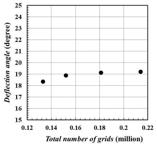
Figure 2.
Computed results of meshes with different grid amounts.
To validate the accuracy of the numerical method, simulations and experiments were conducted and compared. Limited to the experimental conditions, the primary jet velocity is 34 m/s. The nozzle time-average pressure coefficient distributed along the upper nozzle wall is selected as the judgment index when the deflection angle is 13 degrees. As shown in Figure 3, the maximum difference between the experiment and simulation result is less than 0.02. It indicates that the numerical method applied can accurately predict the actual flow situation.
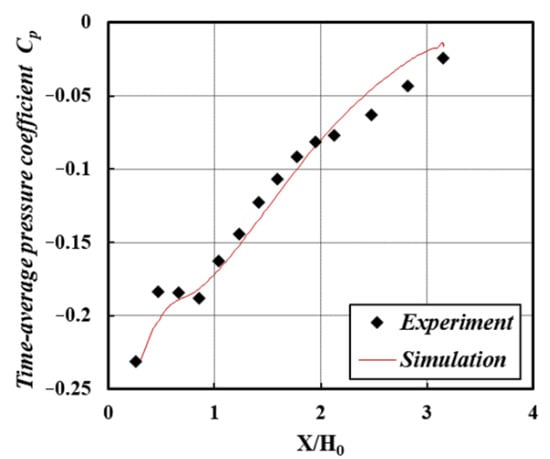
Figure 3.
Comparison of time-average pressure coefficient along the upper wall.
2.3. Relevant Definitions
The method applied to determine the deflection angle is the same as all evaluated simulation cases in this work. In detail, we selected the point with the maximum velocity on the section of x = 0.4 m based on time-average flow field, and marked it as point A. The included angle between velocity direction at point A and x direction is defined as the deflection angle. Thus, the deflection angle can be defined as:
where denotes x velocity component at point A and denotes the y velocity component.
Momentum coefficient is an important dimensionless parameter to evaluate the efficiency of active control means. For zero-mass periodic jets with sinusoidal variation (including DSJ), considering air as an incompressible gas, the momentum coefficient can be defined as:
where is the peak velocity of synthetic jets, is the height of dual synthetic jet exits, is the velocity of the primary jet and denotes the height of the primary jet outlet. denotes the number of zero-mass synthetic jets activated for control and n = 2 for a single DSJ actuator.
3. Results
3.1. Control Characteristics of Thrust Vectoring
To illustrate the effectiveness of DSJ in this configuration, Figure 4 shows the velocity contours of the flow field under different conditions. The primary jet velocity is (based on the height of primary jet inlet, corresponding to Re = 3.9 × 10⁴). The DSJ peak velocity in Figure 5b is set as and its frequency is (based on the height of primary jet inlet, corresponding to St = 0.25).

Figure 4.
Velocity contours of flow field with no control (a), co-flow effect (b) and DSJ control (c) (= 100 m/s).
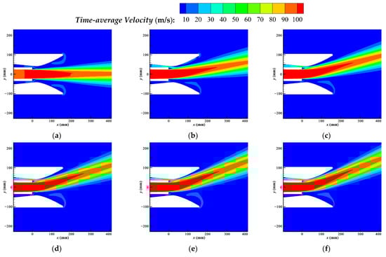
Figure 5.
Time-average velocity contours of controlled flow with DSJ of different intensities. (a) 10 m/s (0.04%), (b) 30 m/s (0.36%), (c) 50 m/s (1.00%), (d) 70 m/s (1.96%), (e) 90 m/s (3.24%), (f) 100 m/s (4.00%).
The activation of DSJ makes the primary jet deflect upward; meanwhile, the secondary jet is accelerated. The primary jet finally gets a stable vector downstream. The primary jet is vectored upside with an eventual mean angle of approximately 18 degrees. The secondary jet will attain a mass flow of 0.541 kg/s by the ejection of the vectored primary jet and DSJ. As a contrast, injecting a secondary jet with the same mass flow can lead to a deflection of 4 degrees alone by the co-flow effect, as shown in Figure 4b. In this configuration, the properties of DSJ are critical in the deflection of the primary jet. Meanwhile, through the ejection effect enhanced by DSJ, the deflected primary jet activates the secondary jet to be a co-flow, offering an improvement in deflection performance.
To investigate the control characteristics of this configuration, simulations are implemented with different DSJ peak velocities (10 m/s, 20 m/s, …, 100 m/s). The velocity distribution, deflection angles, and velocity distribution, are shown and analyzed as follows.
Figure 5 shows the time-average velocity distribution of controlled flow with different DSJ peak velocities. The DSJ frequency is maintained at in this work. As shown in the velocity contours, the vectoring becomes observable when peak velocity increases to 30 m/s and increases as DSJ peak velocity increases.
Figure 6 shows the variation of the deflection angle with DSJ peak velocity and the momentum coefficient. To most FTV means, the changing law between the deflection angle and DSJ peak velocity was supposed to be characterized by a dead zone, a linear control region, and saturation (according to Mason [5]). In this configuration, the establishment of deflection occurs when DSJ peak velocity is less than 20 m/s, and the control characteristic remains linear with peak velocity until the deflection angle reaches 23 degrees. Considering that the geometric exit angle of the nozzle is 28 degrees (which limits the maximum of the deflection angle), it shows a comparatively linear control characteristics in almost all control ranges. The highest efficiency occurs at , ranging from 0 to 0.5%, and the deflection angle reaches 18 degrees at of 1.96%. This indicates that this configuration has good efficiency performance in FTV control.
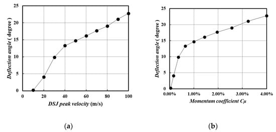
Figure 6.
Variation of deflection angle with DSJ peak velocity (a) and DSJ momentum coefficient (b).
3.2. Pressure Characteristics of Flow Field
This section investigates the controlled flow in pressure characteristics. The time-average pressure distributions of the controlled flow with different DSJ peak velocities are shown in Figure 7.
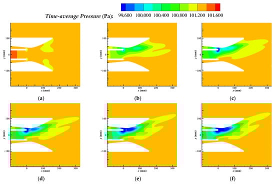
Figure 7.
Time-average pressure contours of the controlled flow with DSJ of different intensities. (a) 10 m/s (0.04%), (b) 30 m/s (0.36%), (c) 50 m/s (1.00%), (d) 70 m/s (1.96%), (e) 90 m/s (3.24%), (f) 100 m/s (4.00%).
Based on time-average pressure, the iconic flow field structure is the low-pressure zone formed by DSJ. There are two cores of the low-pressure zone, one near the DSJ actuator exits and the other located at the wall of the throat. The greater the DSJ peak velocity, the larger the low-pressure zone. In addition, DSJ also reduces the pressure in the primary jet outlet. In Figure 8, the upper surface and outlet section are selected to visually compare the pressure change under different peak velocities.
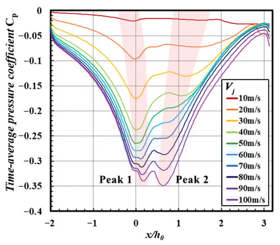
Figure 8.
Time-average pressure coefficient distributed along the upper wall.
Corresponding to two low-pressure core areas, two peaks of low-pressure zones along the nozzle wall are shown in Figure 7. Peak 1 is close to the exits of DSJ, directly caused by DSJ. With the augmentation of DSJ peak velocity, the growth rate of the low pressure in peak 1 decreases gradually, and the position of peak 1 moves downstream slightly. Peak 2 of the low-pressure zone appears on the wall of the throat, further downstream of peak 1.
With small DSJ velocity (below 50 m/s), the augmentation of peak 1 is significant, while the primary jet is far from the wall and peak 2 is not yet established. When the DSJ peak velocity is above 60 m/s, peak 2 begins to be established with an obvious augmentation while the augmentation of peak 1 is descending. This shows the significant effect of the wall on deflection when the primary jet is close enough to the wall. Eventually, the establishment of a low-pressure zone maintains a relatively stable level in all deflection angles. This indicates that the direct effects of DSJ (corresponding to peak 1) and the evolution of flow of the controlled primary jet (corresponding to peak 2) provide comparable contributions in deflection.
3.3. Periodic Evolution of Flow Field
To investigate the evolution of controlled flow, the characteristics of flow field in a DSJ cycle are explored. Figure 9 shows the velocity and pressure distribution of the flow field near the outlet at four typical moments (0T, T/4, T/2, 3T/4) of the DSJ cycle, starting from 0.1 s. To control flow, at the T/4 moment, the upper exit of DSJ is blowing at peak velocity, while the lower exit is sucking at peak velocity. Parts of the primary jet are absorbed in the DSJ cavity, and a strong low-pressure zone is formed downstream, which causes a substantial deflection of the primary jet. The blowing at the upper exit does not have a significant impact at this stage. At the T/2 moment, the upper exit finishes blowing and is going to absorb, while the lower exit is in the opposite situation, and the velocity of both exit inlets is almost zero. The primary jet is deflected at the previous moment develop to attach to the wall and the low-pressure zone generated at previous moment extends in the primary jet tunnel. At the 3T/4 moment, the upper exit of DSJ is absorbing at peak velocity, while the lower exit is blowing at peak velocity. The primary jet deflected at the moment of T/4 begins to attach to the wall. The pressure rises at the attachment area as the wall blocks the y-direction velocity of the primary jet, indicating that the primary jet is continuously deflecting when passing through the low-pressure zone. The low-pressure zone extends and moves downstream. The secondary jet is accelerated by the ejecting of the attached primary jet and the absorbing of the upper exit. An adverse pressure gradient occurs between the low-pressure zone and high-pressure attachment, and a separation vortex occurs at the throat. At the 0T moment, the upper exit finishes absorbing and is going to blow, while the lower exit is in the opposite situation. The separation vortex moves downstream. Throughout the cycle of flow-field evolution, the low-pressure generated by DSJ, the ejecting enhanced by DSJ, and the co-flow effect produced by the accelerated secondary jet all seem to play roles in the deflection of the primary jet.
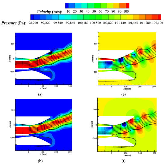
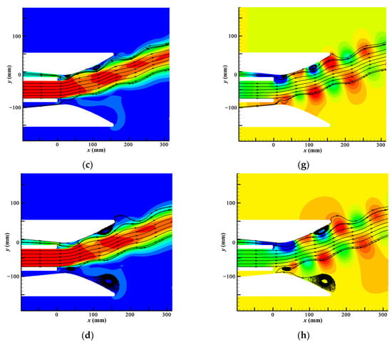
Figure 9.
Periodic variation of velocity and pressure near the DSJ (= 70 m/s). (a) T/4 velocity, (b) T/2 velocity, (c) 3T/4 velocity, (d) 0T velocity, (e) T/4 pressure, (f) T/2 pressure, (g) 3T/4 pressure, (h) 0T pressure.
4. Conclusions
A novel method of thrust vectoring based on DSJ and its configuration are proposed and evaluated by simulations. Different from previous schemes, it has two passive secondary flow outlets to stabilize the primary jet, and a finely designed nozzle wall geometric shape to optimize deflection capability. Numerical results reveal that this configuration has a high efficiency in deflecting a primary jet with a velocity of 100 m/s and a height of 50 mm and shows comparatively linear control characteristics in almost all control ranges.
For the momentum coefficient , the highest efficiency occurs at , ranging from 0 to 0.5%, and the deflection angle reaches approximate 18 degrees at a of 1.96%. The low pressure generated by DSJ, the ejecting enhanced by DSJ, and the co-flow effect produced by accelerated secondary jet all seem to play roles in the deflection of the primary jet.
Since the primary jet is strong enough to drive a small aircraft, the potential of dual synthetic jets to provide FTV control is initially revealed. The demonstrated control capability of DSJ makes it possible to provide thrust vector control without any moving parts or air supply. The detailed structure of flow field and the mechanism of this method need to be further studied.
In the future, relative experimental observations will be conducted to further investigate this mechanism, and flight tests will be implemented to further verify its effectiveness and control characteristics.
Author Contributions
Writing: original draft, J.-F.L.; writing: review and editing, Z.-B.L., X.D., Z.-J.Z., S.-Q.L., Q.L. and Y.-X.Z. All authors have read and agreed to the published version of the manuscript.
Funding
This research was funded by the National Natural Science Foundation of China, grant numbers U2141252, 11972369, 11872374, the Excellent Youth Foundation of Hu’nan Scientific Committee, grant number 2020JJ2031 and the Cultivation Program for Young Talents in College of Aerospace Science and Engineering, grant numbers ZD-22-02.
Institutional Review Board Statement
Not applicable.
Informed Consent Statement
Not applicable.
Conflicts of Interest
The authors declare no conflict of interest.
References
- Deng, R.; Kim, H.D. A study on the thrust vector control using a bypass flow passage. Proc. Inst. Mech. Eng. Part G J. Aerosp. Eng. 2015, 229, 1722–1729. [Google Scholar] [CrossRef]
- Miller, D.N.; Yagle, P.J.; Hamstra, J.W. Fluidic throat skewing for thrust vectoring in fixed-geometry nozzles. In Proceedings of the 37th Aerospace Sciences Meeting and Exhibit, Reno, NV, USA, 11–14 January 1999; p. 365. [Google Scholar]
- Deere, K.A.; Berrier, B.L.; Flamm, J.D. A Computational Study of a Dual Throat Fluidic Thrust Vectoring Nozzle Concept. In Proceedings of the 41st AIAA/ASME/SAE/ASEE Joint Propulsion Conference & Exhibit, Tucson, Arizona, 10–13 July 2005; p. 3502. [Google Scholar]
- Flamm, J.D. Experimental study of a nozzle using fluidic counterflow for thrust vectoring. In Proceedings of the 34th AIAA/ASME/SAE/ASEE Joint Propulsion Conference and Exhibit, Cleveland, OH, USA, 13–15 July 1998; p. 3255. [Google Scholar]
- Mason, M.S.; Crowther, W.J. Fluidic thrust vectoring for low observable air vehicles. In Proceedings of the 2nd AIAA Flow Control Conference, Portland, OR, USA, 28 June–1 July 2004; p. 2210. [Google Scholar]
- Heo, J.Y.; Sung, H.G. Fluidic thrust vector control of supersonic jet using coflow injection. J. Propuls. Power 2012, 28, 858–861. [Google Scholar]
- Warsop, C.; Crowther, W.J.; Shearwood, T. NATO AVT-239: Flight demonstration of fluidic flight controls on the MAGMA subscale demonstrator aircraft. In Proceedings of the AIAA Scitech 2019 Forum, San Diego, CA, USA, 7–11 January 2019; p. 0282. [Google Scholar]
- Wen, X.; Zhou, K.W.; Liu, P.C.; Liu, Y.Z. Schlieren visualization of coflow fluidic thrust vectoring using sweeping jets. AIAA J. 2022, 60, 435–444. [Google Scholar] [CrossRef]
- Gu, R.; Xu, J.; Guo, S. Experimental and Numerical Investigations of a Bypass Dual Throat Nozzle. ASME J. Eng. Gas Turbines Power 2014, 136, 084501. [Google Scholar] [CrossRef]
- Xiao, Z.Y.; Gu, Y.S.; Jiang, X.; Chen, Z.B. A new fluidic thrust vectoring technique based on ejecting mixing effects. Acta Aeronaut. Astronaut. Sin. 2012, 33, 1967–1974. (In Chinese) [Google Scholar]
- Cao, Y.F.; Gu, Y.S.; Cheng, K.M.; Xiao, Z.Y.; Chen, Z.B.; He, K.F. Proportional control of jet deflection with passive secondary flow. Acta Aeronaut. Astronaut. Sin. 2015, 36, 757–763. (In Chinese) [Google Scholar]
- Cao, Y.F.; Gu, Y.S.; Han, J.X. Development and flight testing of a fluidic thrust vectoring demonstrator. Acta Aerodyn. Sin. 2019, 37, 593–599. (In Chinese) [Google Scholar]
- Gong, D.S.; Gu, Y.S.; Zhou, Y.H.; Shi, N.X. Control law of passive fluid thrust vector nozzle based on thermal jet of micro turbojet engine. Acta Aeronaut. Astronaut. Sin. 2020, 41, 123609. (In Chinese) [Google Scholar]
- Wen, X.; Tang, H.; Duan, F. Interaction of in-line twin synthetic jets with a separated flow. Phys. Fluids 2016, 28, 043602. [Google Scholar] [CrossRef]
- Wang, C.L.; Duan, F.; Tang, H. Active control of two-dimensional vortex-induced vibration of a circular cylinder using a pair of synthetic jets. In Symposium on Fluid-Structure-Sound Interactions and Control; Springer: Singapore, 2017. [Google Scholar]
- Luo, Z.B.; Zhao, Z.J.; Liu, J.F.; Deng, X.; Zheng, M.; Yang, H.; Chen, Q.; Li, S. Novel roll effector based on zero-mass-flux dual synthetic jets and its flight test. Chin. J. Aeronaut. 2022, 35, 1–5. [Google Scholar] [CrossRef]
- Smith, L.B.; Glezer, A. Vectoring and small-scale motions effected in free shear flows using synthetic jet actuators. In Proceedings of the 35th Aerospace Sciences Meeting and Exhibit, Reno, NV, USA, 6–9 January 1997; p. 213. [Google Scholar]
- Smith, L.B.; Glezer, A. Jet vectoring using synthetic jets. J. Fluid Mech. 2002, 458, 1–34. [Google Scholar] [CrossRef]
- Pack, L.G.; Seifert, A. Periodic excitation for jet vectoring and enhanced spreading. J. Aircr. 2001, 38, 486–495. [Google Scholar] [CrossRef]
- Chiekh, M.B.; Jean-Christophe, B.; Miche, S. Synthetic jet control for flows in a diffuser: Vectoring, spreading and mixing enhancement. J. Turbul. 2003, 4, 032. [Google Scholar] [CrossRef]
- Luo, Z.B.; Xia, Z.X.; Liu, B. New generation of synthetic jet actuators. AIAA J. 2006, 44, 2418–2420. [Google Scholar] [CrossRef]
- Luo, Z.B.; Xia, Z.X.; Xie, Y.G. Jet vectoring control using a novel synthetic jet actuator. Chin. J. Aeronaut. 2007, 20, 193–201. [Google Scholar] [CrossRef][Green Version]
- Kim, J.Y.; Ghajar, A.F.; Tang, C.; Foutch, G.L. Comparison of near-wall treatment methods for high Reynolds number backward-facing step flow. Int. J. Comput. Fluid Dyn. 2005, 19, 493–500. [Google Scholar] [CrossRef]
- Luo, Z.B. Principle of Synthetic Jet and Dual Synthetic Jets, and their Applications in Jet Vectoring and Micro-Pump. Ph.D. Thesis, National University of Defense Technology, Changsha, China, 2006. (In Chinese). [Google Scholar]
Publisher’s Note: MDPI stays neutral with regard to jurisdictional claims in published maps and institutional affiliations. |
© 2022 by the authors. Licensee MDPI, Basel, Switzerland. This article is an open access article distributed under the terms and conditions of the Creative Commons Attribution (CC BY) license (https://creativecommons.org/licenses/by/4.0/).