1. Introduction
Actuation in aerospace has benefited in recent years from considerable technological improvement due to the substitution of conventional actuation with electrical. Landing gear (LG) systems are a critical part of the aircraft, they rely on the efficiency and safety of the actuation systems that control the LG movements, such as extension/retraction or the deploy/stow, their duration, the brakes, and the steer [
1].
A continuous effort has been made to substitute hydraulic conventional systems with novel electromechanical devices [
2]. The LG actuation system is dedicated to the electronic control and sequencing of the LG, and the related vane doors. In particular, sensors are necessary to monitor gear and door positions and to provide data for controlling the sequence of their activation. These sensors are an integral part of the actuation system and provide reliable information on the actual operational status of the LG. They help to ensure that the aircraft’s LG remains stowed while the aircraft is in the air and deploys only at landing. In [
3], different electro-hydraulic and electro-mechanic actuation architectures for a light VTOL vehicle are sized and compared in order to identify the optimal design.
The electrification of aircraft subsystems is one focus of aerospace research to increase the efficiency of aircraft: two alternative actuator types as possible replacements are investigated in [
4], and these are an Electro-Mechanical Actuator (EMA) and an Electro-Hydrostatic Actuator (EHA). Simplified weight estimation methods from the literature, as well as developed methods, are used to estimate the weight of the different components an EMA or EHA consists of.
Adaptive landing gear is proposed in [
5], to overcome off-field landing possibilities, by an innovative actuation system, composed of a parallel arrangement of motor and brake, which relieves the motor from large impact loads during hard landings.
Weight on Wheels (WoW) systems are aimed at indicating whether the wheels are sustaining a fraction of the aircraft’s weight, then revealing whether the vehicle is on the ground. They take advantage of sensors and monitoring systems, such as proximity sensors [
6]. WoW systems are essential because they prevent accidents relating to the incorrect position of the LG and inappropriate operation of various systems at ground or in flight conditions. Thrust reversers, nose wheel steering, trim, and autopilot are examples of systems that take advantage of the presence of the WoW system. Non-functional or partially functional WoW systems can send intermittent electrical signals to LG, in turn causing intermittent pressure in the hydraulics, which can finally cause un-commanded extensions. LG deployment or retraction at the wrong time can produce a gear-up or belly landing, so, precise determination of the time the wheels contact the runway may be crucial for automatic control systems and active dumpers [
7].
Even RPAS (Remotely Piloted Aircraft Systems) have some problems related to detecting the instant of landing. While such information may be relevant to adjusting the mode and parameters of the control system, restrictions on the size and weight of those aircraft do not allow the installation of physical systems, practically. So, virtual sensors do appear a viable solution, as widely reported in the literature [
8,
9,
10].
WoW systems may have different sizes and shapes and implement different technologies. In any configuration, they complete the avionics. They may use sensor networks on the wheels to gather information about their position and weight-bearing status. Such networks may be classified into two basic types: proximity sensors, using special circuitry to detect an interruption of a magnetic field, associated with their position, and mechanical switches, relying on mechanical contacts to create the circuit. Examples of this latter type employ radially variable differential transformers (RVDT), or linearly variable differential transformers (LVDT). In both these cases, the position of selected LG components, like shock struts (as in the case of the Black Hawk helicopter) or drag beams, is detected as the aircraft lands. Their intrinsic limitation is connected to the fact that they assume proper operation of the LG. Therefore, if those mechanical devices do not work properly, WoW system information may be false, with unpleasant consequences. In other cases, WoW systems are based on strain gauges mounted on the LG structure, such as the one proposed by Airbus [
11]. It measures shear stress and exhibits a lower trigger point than traditional systems.
Other interesting architectures use cameras attached to the aircraft hull to estimate LG compression rate [
12]. Sikorski introduced an automatic system using remote Laser Imaging Detection and Ranging (LIDAR) devices for detecting Weight-on-Wheels on a helicopter LG [
13]. A fully integrated system combining flight management and WoW systems functions during rotorcraft take-off and landing is presented in [
14]. Once more, for rotary-wing aircraft, an automatic failsafe mechanism for revealing Weight-on-Wheels on LG is proposed in [
15]. A further concept, addressing the vibratory behaviour of aircraft LG is presented in [
16].
Within the Unmanned Low-Cost Testing Research Aircraft (ULTRA) project, a novel autonomous takeoff and landing system included capabilities to detect the wheels’ ground contact [
17], by combining data from the usual, and a specific, contact sensor. Such a device consisted of a lever-spring couple placed close to the LG, which was pressed during the impact with the soil. The spring compression finally produced a force on a load cell. The reliability of the system’s predictions was strengthened by complementary statistical models: for instance, the limited motion on the ground was used to estimate the possibility that the aircraft was actually on the terrain, or in landing, take-off, or flight conditions [
18].
Indeed, establishing the exact touchdown point and time seems an easy task for an external observer in a steady position with respect to the ground, and possibly equipped with dedicated instrumentation. However, such a process is very complicated if it takes place directly on board a common aircraft [
19,
20]. A study was conducted on an A320 airliner to detect the landing point based on data recorded from altimeters and accelerometers [
21]. This is even more complex for small aircraft, which do not have access to dedicated sensors, and most of the information comes from Global Navigation Satellite System (GNSS) receivers [
22]. Possible space and time accuracy requirements pose other challenges to the estimates, relying on little medium-quality data. That is particularly true for sport, general aviation (GA), and gliders (CS-23 class), while transport and corporate aircraft are generally equipped with WoW sensors. The use of GNSS/INS (inertial navigation system) and an optical sensor for determining the take-off and landing performance of a GA aircraft on a grass airfield, is reported in [
23], while the same task is approached with a dynamometer in [
24].
It may be of some interest to report some occurrences on in-service aircraft, as reported by EASA. In 2010, it was determined that a short circuit occurring on WoW proximity sensor wiring could have led to the simultaneous de-power of all WoW proximity sensors of that part of the system. EASA then reported that such a loss of information from the Weight-on-Wheels system could have compromised the pilot’s capacity to react to unusual or failed landing conditions. It, therefore, issued an Airworthiness Directive (AD) to modify the WoW system robustness with respect to the abovementioned short-circuit events [
25]. A similar measure was taken on the AW169, after it was established that an inappropriately tightened WoW system support could have resulted in an improper WoW switch performance, in turn potentially leading to degraded stabilisation in flight, possibly resulting in reduced control of the vehicle. Therefore, EASA issued an AD requiring proper modification of the WoW support installation close to the main fitting of the MLG [
26]. Recently, a system for the determination of Weight-on-Wheels by using LIDAR has been developed [
27].
Such examples bear witness to the importance of the WoW systems, and the opportunity to both minimise their complexity and use passive sensors that do not require electrical isolation.
Implementation of fibre optics goes in that direction, by potentially substituting massive electrical circuitry with a few cables and optical devices. In principle, the system may be made extremely modular, so that it consists of many parts, independent of each other, without sacrificing the completeness of the information. Appropriate load measurement on LG can be used for weight on wheel purposes [
28,
29]. Fibre optics technology is used in many structural health monitoring applications [
30] and can be used to monitor load conditions in LG.
In a previous paper, the authors analysed the characteristics of the dynamic response to ground impact and derived important information to identify Hard Impact conditions [
31]. This paper describes preliminary tests performed in the laboratory on a simple test article, even though representative of an actual LG mounted on a model aircraft. The aim of this analysis is to perform a preliminary verification of the use of FBG sensors as strain detectors, to determine the actual standing of the aircraft to the ground. The idea originates from the consideration that, when the aircraft is at ground, its own weight causes a stress state on the support elements, namely the LG. As this tensional state vanishes, it can be guaranteed that the vehicle has detached from the ground. In order for this methodology to be satisfactorily applied, the following conditions shall be respected, at least:
The FBG strain shall refer to the landing gear detachment condition (arbitrary reference strain, usually set to zero);
The FBG sensitivity shall be under 10 με, in order to avoid misinformation and consequent issues, even catastrophic. All these conditions are satisfied by the selected fibre optics.
That the sensitivity is lower than 10 με means that, for common use of the landing gear, having stated to 3000 με its functional values, 10 με corresponds to 0.33% error, i.e., 3 kg for a vehicle having an operative weight of 1 ton, standing on that landing gear, solely. This measure can be retained as acceptable. Conversely, the system can wait till the strain measurement crosses the zero-line for a consistent time (to be defined), i.e., the measured strain turns negative because of the measurement uncertainty.
2. Materials and Methods
WoW systems indicate whether the weight of an aircraft is resting on its wheels. A WoW system consisting of a sensor network can be used to monitor the structure of LG under complex loading conditions, and photonic sensors on fibre optics seem to be good candidates to accomplish this task.
Fibre Bragg gratings (FBGs) show clear advantages for high multiplexing capability, lightweight, high sensitivity, and low transmission loss; in addition, the sensor signal can be collected from longer distances making it suitable for remote sensing [
32]. FBG sensors have been used for years in many demanding applications in harsh environments as an alternative to traditional electrical and mechanical sensors. They exhibit many advantages over their electrical counterparts. In fact, the large, heavy, and difficult traditional wiring can be greatly simplified by the minimal size, weight, and architectural complexity with more multiplexing capabilities making fibre optics useful for use in sensor networks, embedded, bonded, or immersed in various aircraft structures or components. Moreover, fibre sensors, being electrical passive elements, do not interfere with or suffer interference from on-board equipment, and do not require electrical isolation. Fibre optics are excellent candidates for being integrated into LG structures to measure strains because of their many advantages, such as high sensitivity, electromagnetic immunity, minimum harness, minimum weight, intrusiveness (typical diameter is around 125 µm), and multiplexing capability. Their use in LG is innovative and represents the state of the art. Fibre Bragg Gratings (FBG) represent a largely mature technology for measuring structural deformations [
33], currently present in many industrial applications.
To perform a preliminary assessment of an FBG-Based WoW system integrated into landing gear, a test campaign has been conducted at the laboratory level to simulate take-offs and landings of an aircraft. The LG was mounted on the impact slider of a drop tower in order to constantly monitor the vertical displacements of the LG and its presence on the ground.
2.1. Test Equipment
The test setup that is presented in this section was used in a multi-target experimental test campaign for the CleanSky2-ANGELA project, the same test article (TA) and drop tower were used for the hard impact measurement [
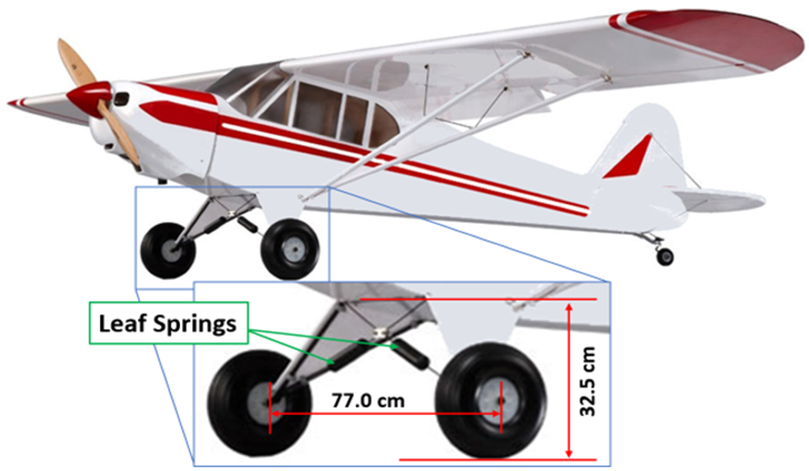
28]. The test article consists of a leaf-spring landing gear of a 1:3 Piper PA-18 Super Cub aircraft scaled model,
Figure 1. The landing gear is composed of a central part consisting of a flat plate, parallel to the ground and of two lateral extensions departed from the central plate, in the shape of triangular wings, about 30 degrees inclined with respect to the ground. The wheels are installed on their tips, one per side, are solid, and have a diameter of 17.0 cm and a width of 5.0 cm.
The central part of the landing gear is equipped with two spring ties, contributing to the energy absorption along the landing phase. The two crossing springs are fixed in the inner part of the TA, in line with the wheels. The overall dimension of the TA is 77.0 × 32.5 cm (width by height), for a weight of 2.29 kg. The TA has been removed from the aircraft and mounted at the impact slider (impactor) of a drop tower at CIRA Aerospace Structures Impact Laboratory (LISA).
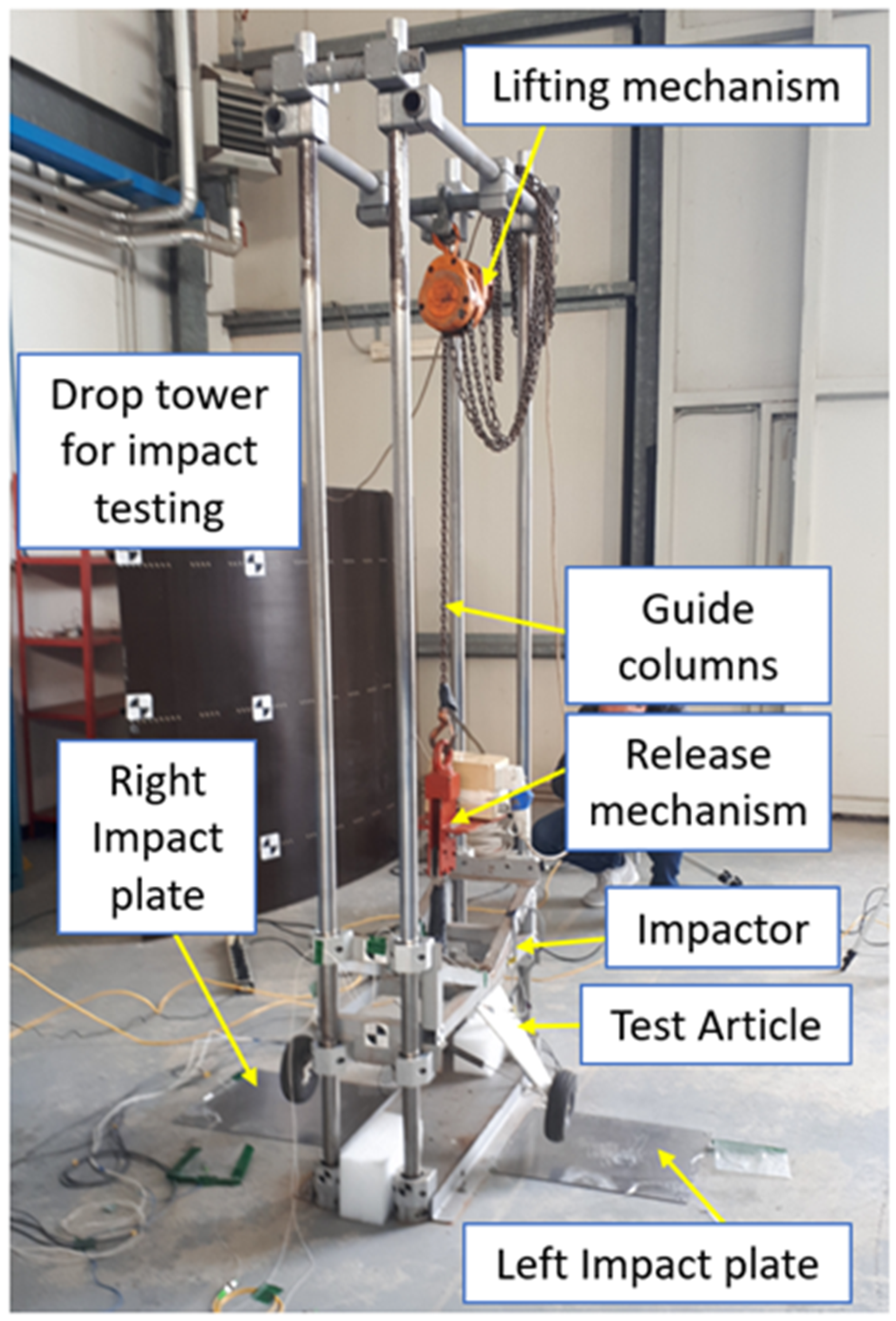
The drop tower is composed of four rigid uprights that guide a slider along its vertical movement. The tower is bound to the floor with a support base 80 × 32 cm sized, and can perform up to 2 m height drops,
Figure 2. The TA is secured to the impactor by means of a dedicated interface plate. The combined weight of the impactor and the interface plate sum to 25.77 kg, so the total dropping mass made by the impactor, the interface plate, and the TA was 28.06 kg. The drop tower was used to impose up-wards and downwards vertical displacements to the TA; it was operated by a lifting mechanism allowing only that kind of movement of the dropping mass through a system of pulleys and vertical guides. Two impact plates are installed on both sides of the impact tower, see
Figure 2. They are ground-bound steel plates, 49 × 38 cm sized, and have a thickness of 1 mm. The plates are equipped with an FBG sensor each to monitor landing gear detachment independently, for each leg. In this way, the measurement system can sense the presence of any TA asymmetry and the exact time at which each wheel is detached from the ground.
2.2. The FBG Arrays
The TA and the two plates are equipped with FBG sensors. They all have a length of 10 mm and are photo-inscribed on a single-mode optical fibre, coated with acrylate; the gratings recoating is in polyimide. The gratings are bonded on the structural surfaces by cyanoacrylate, rapidly curing at room temperature.
The FBG gratings are arranged in three arrays, for a total of 6 FBG, whose characteristics are summarized in
Table 1. Two arrays are integrated into the TA (
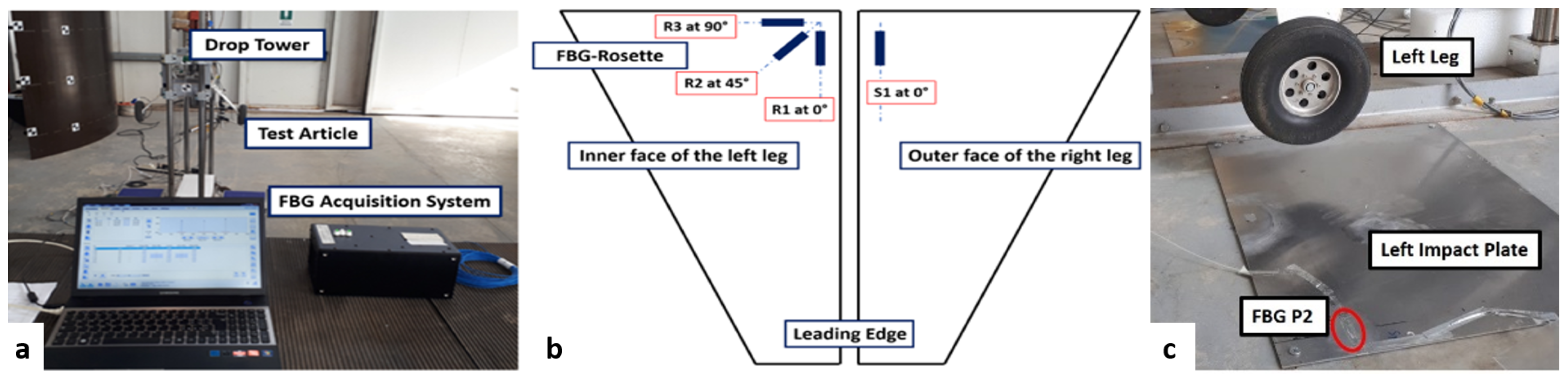
Figure 3b), and an array on the impact plates. On the inner face of the left leg of the LG, three FBG (R1, R2, and R3) are deployed in a rosette configuration at 0°/45°/90° with respect to the leading edge of the test article, respectively (
Figure 3b). On the outer face of the right leg of the LG, an array composed of a single grating (S1) is positioned parallel to the leading edge, hence, oriented at 0° (
Figure 3b). As evident from the pictures, the first two arrays are placed in the upper part of the legs, where deformations are expected to be the largest, as the TA impacts the ground. The third array consists of two gratings (P1 and P2) installed on the upper surfaces of the right and left impact plates, respectively (
Figure 3c). Therefore, this latter array is deployed on two different physical items.
The three arrays are connected at three parallel channels of the optical interrogator, an Optical Sensing Interrogator (Micron Optics sm130), with an acquisition rate of 1 kHz. The interrogator is connected to a notebook via Ethernet. Signals were registered in real-time; a picture of the acquisition system is shown in
Figure 3a.
The test was carried out in two steps. Initially, the TA rested on the ground with the wheels placed on the two impact plates (
Figure 2). The test article was then lifted to 5 cm height. Then, the TA was let fall freely along the slider, by activating a dedicated release system. The up-rights and the slider guided the TA until it impacted the ground plates with its tyres. The TA was lifted manually, while the drop phase was triggered by a remote control that activated the release system and made the TA fall vertically, with a velocity of 0.99 m/s.
During the test, the signals from the three FBG arrays were acquired to measure strain variations. The gratings on the TA followed the load variations both during the detachment from the ground and the drop. The gratings on the plates offered, during the lifting phase, an instantaneous and continuous comparison of their contact with the TA wheels and at the drop the precise time when the impact occurred, and subsequent rebounds phenomena, till the system returned to static equilibrium.
3. Results
The graphs in
Figure 4 and
Figure 5 report the signals of the FBG sensors during the lifting phase; in particular, they show the strain variation vs. time. The system was initially at rest, with the wheels on the ground-bound steel plates. FBG signals were then set to zero, to define the equilibrium position and the test starting conditions. The graph in
Figure 5 represents a zoom of
Figure 4 to better show the interval when the landing gear came off the ground. Four different phases may be evidenced in
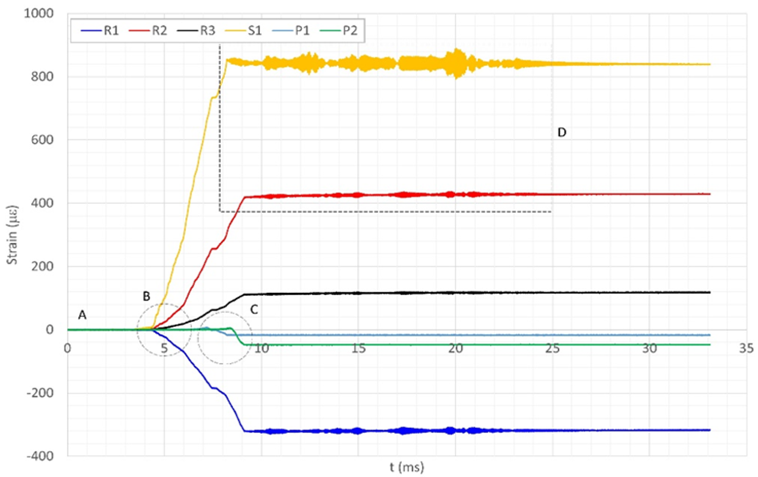
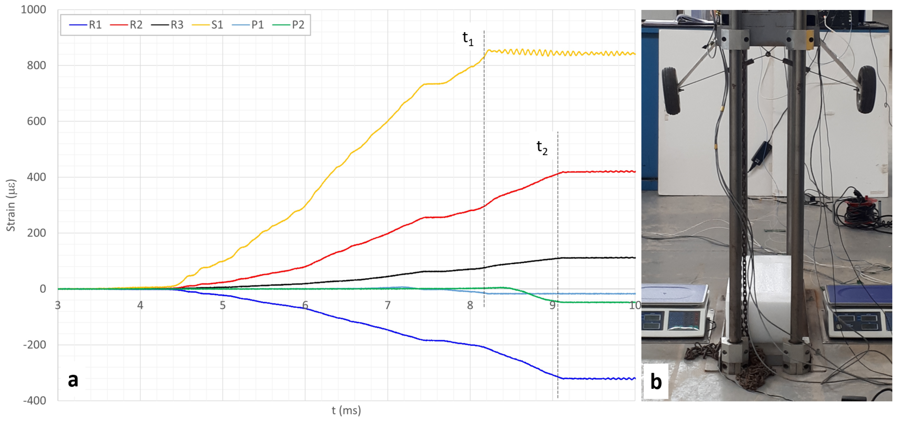
Figure 4, according to the time intervals:
- A.
[0–4 millisecond (ms)] The system is at rest. All the FBG strain data were calibrated, i.e., their output information was set to zero.
- B.
[4–7 ms] The TA is lifted vertically, and the wheels started to detach from the ground, but they were still in contact with it. LG is no more completely standing on the wheels but partially hanging on the plates. The FBG arrays on the LG start sensing the change in load distribution. The strain on the plates is significantly lower than that measured on the instrumented TA.
- C.
[7–8.5 ms] The system starts to lose contact with the plates. Due to a small uneven LG balancing, the right leg comes off before the left leg. At 7 ms the right wheel detaches and the gratings on the left wheel began showing a significant deviation from the initial curve. The left plate was completely unloaded only at 8.5 ms, as the signals attained an almost stationary value. The grating signals of the array on the left leg are perfectly synchronized with that recorded on the left plate: the unloading of the plate corresponds to the max loading at the TA.
- D.
[8.5 ms and beyond] The TA is entirely suspended. The plates are completely unloaded, while the sensors installed on the TA sensed the new force distribution, leading to a variation of the strain. Furthermore, those sensors were able to detect vibrations due to the transition from one configuration to another.
Going into the details of the experiment, in
Figure 5a it is possible to discern the instant t1 when the right wheel started leaving the ground, causing, in turn, a significant change in the loading state of the right plate, and time t2, when the other wheel detached from the ground, leaving the left plate unloaded and again changing the stress distribution. That non-symmetry is confirmed by
Figure 5b, showing a rear view of the drop tower, where it is evident the TA configuration exhibits the right wheel higher than the left one.
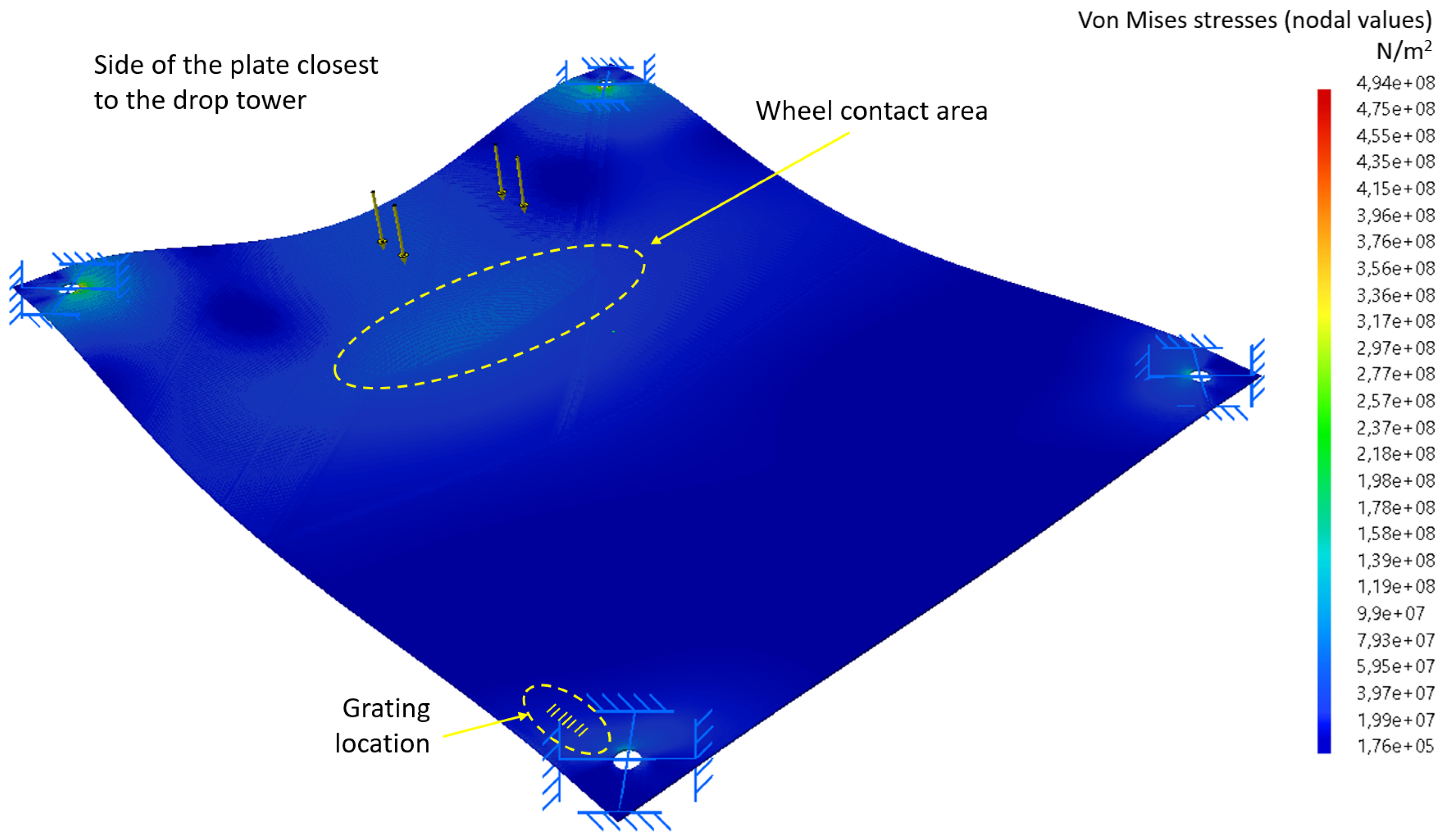
In
Figure 6, a fundamental Von Mises Stresses analysis of the plate under the loads transmitted by the wheel is reported. The weight of the TA causes a natural concavity of the plate, that is pinned at its corners. The grating, installed on the plate on the opposite side from the dropping tower and directed towards the tower itself (
Figure 3c), registers slight traction that is released at the detachment time and then compresses when the TA is airborne. A preliminary Finite Elements analysis was performed on the plates to permit proper arrangement of the two sensors that have the objective of giving a confirmation of the instant of separation between the wheels and the ground, in comparison to the sensors installed on the TA legs. The structural response of the plate is not significant for the purpose of the test,
Figure 6 is presented to allow the reader a better interpretation of the response of the sensors installed on the plates.
As shown in
Figure 3b, R1 and S1 are aligned to the leading edge of the TA; yet, they show opposite trends. In fact, S1 is mounted on the outer surface of the TA right leg, while R1 is deployed on the inner surface of the TA left leg. Therefore, when on the ground, the exterior leg surface is compressed, while the internal is expanded. With the sensor data calibrated at zero when the TA is at rest on the ground, a strain positive is expected for the outer, and a negative one for the inner sensor. As the TA was hanged at the end of its upward movement, the FBG would have been expected to measure an opposite deformation, being the legs slightly deflected towards the inside. In that new situation, the external surface would have experienced an expansion, while the inter a compression.
These assumptions are confirmed in
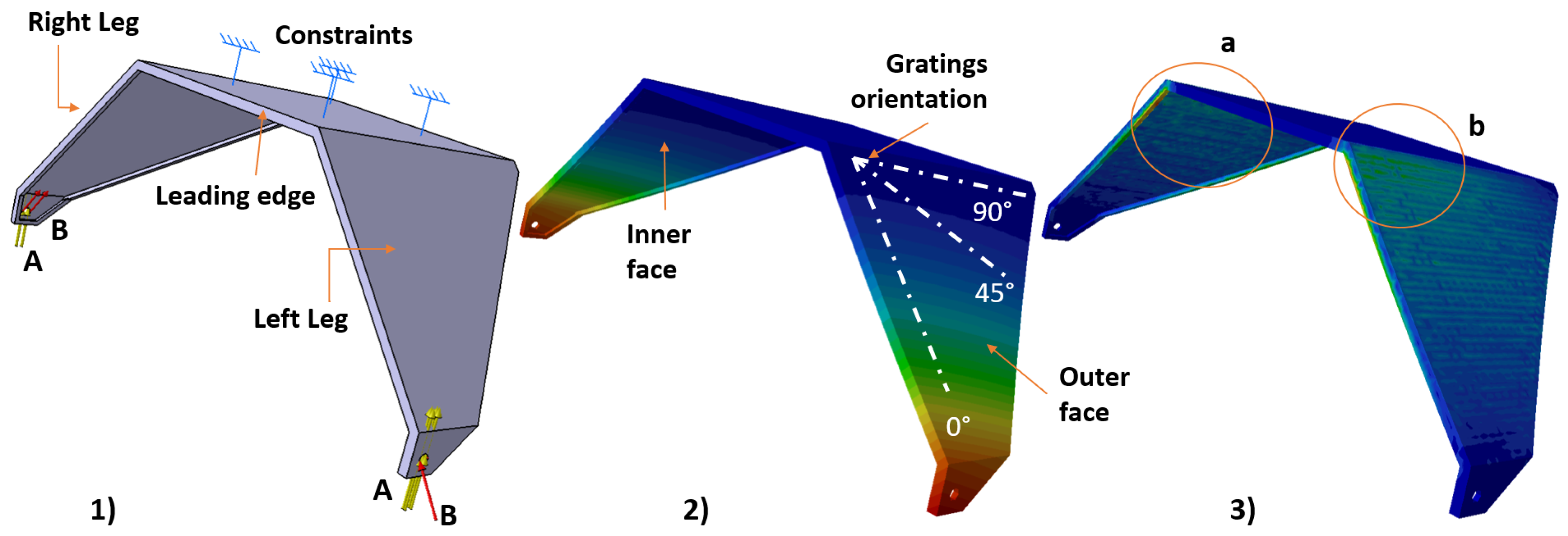
Figure 7 which shows the result of the preliminary static analysis performed on a simplified model of the landing gear. As shown in
Figure 7(a), at rest, the force system was applied to the wheel contact point with the ground, whose resultant corresponded to the weight of the whole system, being made of the impactor, the slides, and the landing gear. In that case, the crossed springs were therefore pulled. A numerical representation of the displacement field is reported in
Figure 7(b); therein, the white dashed lines show the orientation of the sensor. The picture clearly shows that at rest, the landing gear wings are deflected towards the outside. This would have led to an expansion for fibres aligned along the 0° direction, while a compression would have been expected for those oriented along the 90° direction, because of the Poisson effect.
A qualitative analysis showing the Main Stress Tensor is reported in
Figure 8, for the inner and outer surfaces of the TA. Sensors installed on the inner surface showed a lower strain rate than those installed on the outer surface due to the thickening of the leading edge aimed at stiffening the TA. This is highlighted in red in
Figure 7(3) by the stress concentration occurring at the top of the inner face (close to the joint).
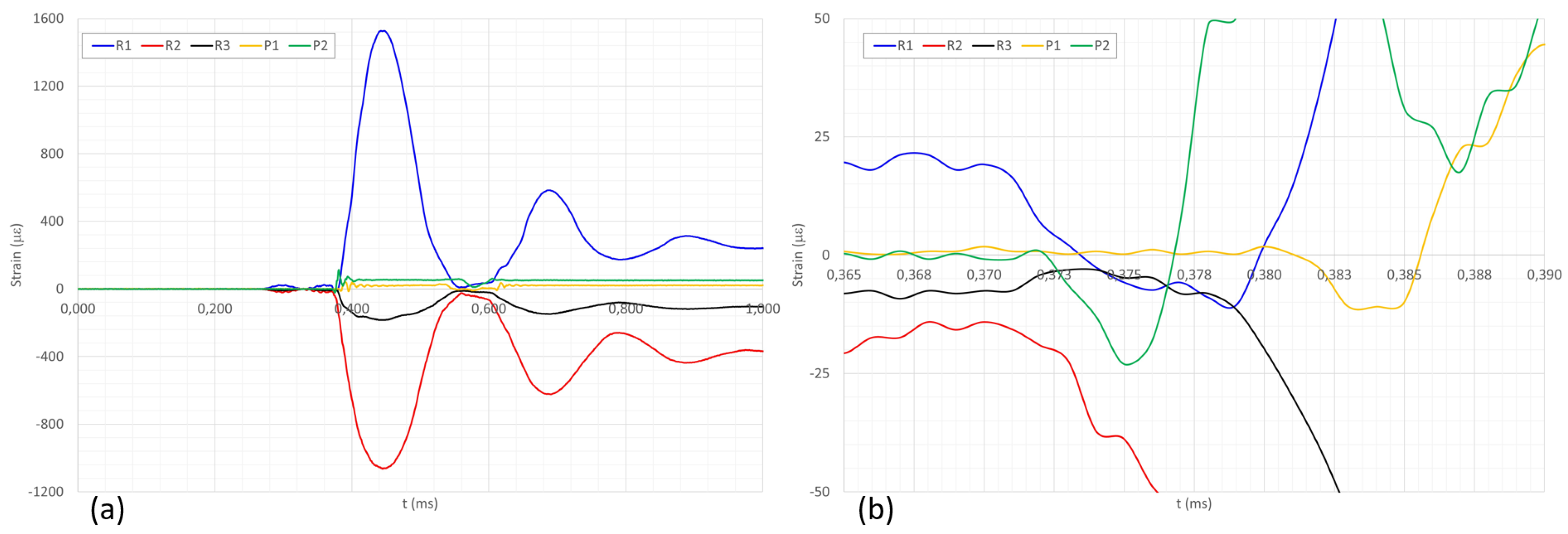
Figure 8a shows an example of the drop test taken from previous tests, during which the same TA is dropped vertically from a height of 5 cm. The graph shows the time variation of the strains measured by the same set of FBGs installed on the TA. In that circumstance, strain gauges and accelerometers were used to compare results with fiber optic sensors, and the results confirmed the validity of the gathered measures [
28]. It is worth reporting this outcome to confirm the sensitivity of the installed sensor set in reading the actual contact between the wheels and the plates, which also detects the asymmetry between the right and left leg shown in
Figure 5a even during a test performed at higher speeds. During the first 0.270 ms of
Figure 8a, the TA is in the rest position, suspended at a height of 5 cm. In this position, the sensor signal was zeroed to indicate the initial conditions of the test. During this interval, it only shows a background noise, which is common to the three sensors installed on the TA (i.e., R1, R2, and R3) as well as the two sensors installed on the plates (i.e., P1 and P2). Between 0.270 and 0.370 ms, the TA is dropped, and the sensors installed on the TA detect an increase in dynamics due to the swinging of the left and right legs during the descent, the two plate sensors still show, exclusively, the background noise indicated above.
Figure 8b shows a magnification of the time interval between 0.365 and 0.390 ms during which ground impact occurs. This is of particular interest, as it shows that the right and left wheels touch the ground at two different times, confirming what was observed earlier in relation to the different heights of the two wheels in resting conditions, as shown in
Figure 5a. As can be seen from the signal variation of sensor P2 (the green line in
Figure 8), which anticipates that of sensor P1 (the yellow line in the same graph), contact with the ground does not occur simultaneously but the contact times are very close one to the other. In this case, the difference is less perceptible than during the lifting phase carried out at a lower speed. This is because, during the lifting test, the TA was lifted manually and slowly (without measuring the lifting speed), during the drop test the trolley reached a speed of 0.99 m/s in free fall.
4. Conclusions
In this paper, we proposed a preliminary assessment of an FBG-based landing gear WoW system. The analysis is aimed at performing an exploratory verification of the use of FBG sensors as strain detectors, to determine the actual standing of the aircraft to the ground. The WoW system is composed of FBG sensors able to measure the strain of the LG structure under the loads due to the operations of the LG itself, such as landing, take-off, or retraction. The operations of the LG are conducted in the frame of the LG actuation system. The proposed WoW system is a real-time sensing system capable of measuring strain variations versus time and able to let the pilot know if there is any load on the landing gear, plus, whether the load is distributed among the legs. To perform the preliminary assessment, a test campaign has been conducted of a WoW system consisting of two FBG arrays mounted on a 1:3 scaled leaf-spring landing gear of the Piper PA-18 Super Cub aircraft model. Lift and drop tests were performed on the landing gear in order to verify the sensitivity of the gratings’ arrays installed on the TA.
The advantages of using fibre optics sensors instead of common monitoring systems are obvious to the usual use of optical instrumentation instead of a purely electronic one (non-EMI, for instance): the multiplexing capability that strongly affects the cabling necessity; the low weight, and the low installation complexity; the high reliability owned by the relevant numbers of optical interrogators available on the market; the relatively low cost; easiness of installation, and a very limited need for space availability. Furthermore, as illustrated in many other works, such systems are fully compatible with other functions like weight and balance, hard landing detection, and so on).
The tested system derives from an architecture originally devoted to weight and balance, and then modified for hard landing detection purposes. As in the referenced examples, the system is proven to match the specific requirement for a weight-on-wheel system (response time, strain accuracy, and so on), confirming its minimal intrusiveness and the possibility of gathering the same information for different aims. In this sense, it is believed the system that is going to be assessed, will have a multifunctional role, therefore further minimizing network complexity, and architecture installation issues, with the possibility of reliance on a single layout.
Test results showed that the installed sensor system was able to detect the moment the landing gear hit the ground during the drop test, and the moment it lifted off the ground during the lift test, with a resolution of one millisecond. The system was even able to distinctly sense a misalignment between the two wheels of the TA by showing a delay between the events recorded by the gratings mounted on the right and left legs of the landing gear, respectively. In addition, the test provided relevant information on the characteristics of the sensor array that will be used in further tests on materials and geometries that conform to real landing gear.
The tested FBGs-set has been found to release coherent information, even though deployed on different parts of the LG (left and right leg, in different configurations—rosette-type, and linear), and the impact plates. The proposed WoW monitoring system is capable of real-time and continuous measures, to detect the presence or absence of load on the landing gear, whether the wheels of the landing gear are in contact with the ground or not, and provide essential automatic information to the pilot during the most critical phases of take-off and landing. So, the FBG WoW system may be considered a robust one. Installation on a prototype LG, but fully functional and extracted from a model aircraft, adds further confidence to the attained results.
In comparison with other solutions encountered in the literature data, it should be said that:
The system satisfies the weight-on-wheel system expectations, and this may be applied to any other WOW system.
A comparison may be carried out on the hardware selection, therefore highlighting the advantages and disadvantages of fibre optics.
Integration with other functions has been highlighted, not necessarily common to other systems.
Considering the outcomes, the installed FBG-based system becomes an integral part of the LG actuation, improves its efficiency in safety-critical applications, and provides reliable information on its operational status. The next steps are planned to take place on real, full-size, full-scale landing gear in order to prove the installability on real elements, and possibly verify its behaviour in operational, or representative conditions.


 ,
, 


