Abstract
Repairing cracks in the concrete of a building is very important to ensure the safety of a nuclear power plant. However, repair work in areas with very strong radiation is very difficult. Many robots have been proposed to solve this problem. However, they cannot operate wirelessly and have problems such as being left as debris in the event of an accident. To solve the problem, this paper investigates the feasibility of sound-driven robots. We focused on Helmholtz resonance to achieve this goal. In this paper, Helmholtz resonators were adopted as the drive source of the actuator, and a new prototype was created by devising the arrangement. We also examined the physical characteristics of the developed prototype. Unlike conventional actuators, the proposed device can be moved remotely simply by irradiating sound from the outside. The advantage of using sound waves is that the robot can move without being affected by electric or magnetic fields. Through some experiments, it was confirmed that the developed actuator can be moved remotely with sound.
1. Introduction
Repairing cracks in building concrete is essentially important for ensuring the safety of nuclear power plants. However, repair work in areas with extremely strong radiation is virtually impossible. There is an urgent need to establish regular repair methods for nuclear power plants. Disaster support robots are expected to become a powerful approach to solve this problem [1,2,3].
However, strong radiation is extremely incompatible with conventional robots that are controlled by electronic circuits and receive control signals through radio waves. For example, many disaster support robots are controlled by electronic circuits, but strong radiation destroys the mounted electronic circuits in a short time. Strong radiation becomes a strong noise for the radio signal used for control, which significantly hinders remote operation.
Traditional robots also have little exit strategy after being used in harsh conditions. Robots used in nuclear power plants will be left at the accident site as debris to be removed once the robots are broken. For example, in 2011, TV media reported a case where a robot was left behind during an investigation of a reactor building [4].
When a robot operates in a nuclear power plant, it is desirable that it can be controlled without being affected by radiation and using electricity as a driving source.
This paper examines sound as a method for driving a robot to solve this problem. Sound waves are a physical phenomenon that is essentially non-interfering with radiation, which is an electromagnetic wave. Since sound waves can be sent from a remote location, they are compatible with work in areas that cannot be penetrated. If a robot controlled by sound can be realized, it will be possible to control the robot from the outside not only in an environment filled with radiation such as a nuclear power plant, but also in a space where radio waves do not reach. For example, the robot can be controlled from the outside not only in an environment filled with radiation, such as a nuclear power plant, but also in a space that is impermeable to radio waves.
In addition, since it is not necessary to mount an electronic board, it is expected that a robot made of only environmentally friendly materials will be realized. To achieve this goal, we use Helmholtz resonance to drive a robot with sound waves.
The rests of this paper are organized as follows: in Section 2, we introduce some related works and clarify the features of our approach. In Section 3, we describe the physics of Helmholtz resonance. In Section 4, we show the results to check the relation between the sound frequency and the wind speed from the device to confirm the consistency between the theoretical framework and the experimental results. Section 5 gives the actuator design driven by Helmholtz resonance and the experimental results of designed actuators’ movements. The conclusion is given in Section 6.
2. Related Works
Many studies on disaster robots have been conducted so far. In the past, there have been studies on humanoid robots used in power plants [5] and small autonomous mobile robots [6] that can be used in pipes. The power is supplied by microwaves, and in the future, the control will also be done by microwaves. Most disaster relief robots are controlled by electric circuits and driven by electricity. However, long-term operation is difficult because strong radiation destroys the electric circuits in a short time.
Robots intended for use in nuclear power plants are also being actively researched [7,8,9,10,11,12,13]. Some of them are designed to prevent radiation damage to electronic circuits and other components. When designing robots, many parts that are not affected by radiation exposure are used. Many robots are also controlled by a wired connection to avoid the effects of radiation.
Soft actuators and soft robots are also actively studied to overcome the limits of typical robotic techniques [14,15,16]. Soft robots have flexible structures and their shapes change depending on its softness. Hence, they have many advantages that conventional robots do not have. For example, soft robots can enter narrow spaces that conventional robots cannot enter [17]. In addition, the soft robot is not easily damaged even if it receives a strong impact such as dropping [18]. Pneumatics is a well-known drive source used in soft actuators. The McKibben actuator is an old example of an air-driven actuator with a long history [19,20]. It is used in various scenarios and technologies such as worm-like robots [21], quadruped robots [22], and humanoid [23,24] and infant robots [25] due to its safeness. There are several other examples of soft robots driven by pneumatic actuators [26,27]. Other authors report soft actuators driven by hydraulic pressure rather than pneumatic pressure [28]. However, these soft actuators require an external pump to control the pressure. Therefore, remote control is difficult because the pump and robot need to be connected by a cable.
On the contrary, there are several studies regarding non-electrically driven actuators. They drive with various stimuli from external environments such as temperature [29,30], pH [31,32], electric field [33], water [34], and light [35]. However, many of these actuators have restrictions on the environment in which they can be used and are difficult to control.
To solve the problem, we pay attention to sound waves. Sound waves are a physical phenomenon that is essentially non-interfering with radiation, which is an electromagnetic wave. Since it is possible to transmit sound waves from a remote location, it is compatible with work in inaccessible areas.
Although the authors have been studying the driving of matter by sound waves, only the movement on the water could be realized [36]. In this paper, we focus on Helmholtz resonance and aim to drive it on land by sound waves.
3. Physics of Helmholtz Resonance
In this section, we describe the details of Helmholtz resonance and its physical formulation. Helmholtz resonance is an air resonance phenomenon that occurs when air is applied to the top of an empty bottle. This phenomenon has been known for a long time and was discovered by Hermann von Helmholtz in the 1850s [37]. The container at this time is called a Helmholtz resonator, and the frequency at that time is called the resonance frequency. The Helmholtz resonance is a resonance that occurs when the air inside a container with an aperture acts as a spring. Let us consider the Helmholtz resonator shown in Figure 1 [38,39,40].
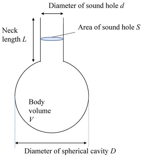
Figure 1.
Model of Helmholtz resonator.
In Figure 1, L represents the neck length. S represents the area of the sound hole. d represents the diameter of the sound hole. V represents the body volume. D represents the diameter of the spherical cavity.
Let us consider the air in the neck part as a piston with mass m. Since m is the mass of the neck part, it can be expressed as follows.
To consider the force applied to the piston, let the outside air pressure be P0. Let V0 be the initial volume of the gas inside. When no force is applied to the piston, the pressure of the gas inside is equal to the outside air pressure. Now, suppose that the piston is pushed in by x and the pressure changes to P and the volume changes to V. The restoring force F applied to the piston can be written as follows.
It is assumed that the expansion and compression of gas by pushing the piston is an adiabatic operation. Then, the following can be obtained from Poisson’s equation.
where γ represents the specific heat ratio.
On the other hand, the following relationship holds between V and V0.
Hence, the following can be derived from Equations (3) and (4).
The following equation is obtained by transforming Equation (5).
It is known that the following approximate expression holds when |ε| is sufficiently smaller than 1.
Based on the fact that Sx is sufficiently smaller than V0, the following approximation is obtained.
Substituting Equation (8) into Equation (2) yields the following equation for F:
Hence, the equation of motion is described as follows:
The equation of motion (10) can be regarded as a simple harmonic motion of the spring constant k where
From the equation of motion, we can obtain the resonant frequency f of the Helmholtz resonator as follows:
where c is the sound speed described as follows:
Considering that not only the inside of the pipe but also the air around the opening vibrates additionally, it is necessary to correct the opening end for the natural frequency. It is known as end correction. The corrected resonant frequency f of the Helmholtz resonator is given by the following equation:
where Leq is the effective length of the neck considering the aperture correction; Leq is given by the following equation depending on the presence or absence of a neck collar when the diameter of the sound hole is d according to the reference [40].
As V is the volume of the sphere, it can be expressed by using the following equation:
On the other hand, S is the area of a circle and is expressed by d as follows:
Substituting Equations (17) and (18) into Equation (14) gives the following equation:
In the case of a sphere with no neck and only a resonance hole, the surface of the sphere acts as a brim and L = 0, so the resonance frequency f is as follows:
From the equation of state, P0 can be described as follows:
where n is the number of moles of the gas. R is the gas constant. T is absolute temperature. Substituting Equation (21) into Equation (13), c can be written as
Let the average molecular weight of the gas be M. M can be written as
Hence, c can be described as follows:
where Tc represents the Celsius temperature. Given that the gas constant is 8.314, the specific heat ratio in air is about 1.403, and the average molecular weight of gas in air is about 28.97 × 10⁻³ [kg/mol], the resonance frequency f is given by the following equations from Equations (20) and (24).
From Equation (25), the resonant frequency f of the sphere in dry air depends on the diameter of the sound hole d, the diameter of the sphere D, and the temperature Tc of the gas. The air in the ball moves depending on the external volume and frequency. If there is a hole on the ball, the moving air will come out. The strength of the coming wind is determined by the intensity of the movement of the air inside, so it is expected to be the strongest when it resonates. We checked it experimentally in the next section.
4. Measurement of Wind Speed Depending on Sound Frequency
During the Helmholtz resonance, a flow of air blows out from the neck of the resonator. To check the consistency between the theoretical framework and the experimental results, we conducted a verification experiment on the relationship between the frequency of sound and the wind speed from the device.
Two experiments were conducted for this purpose. In this study, 44 mm diameter ping-pong balls were used as Helmholtz resonators. We made 5 mm and 5.5 mm holes in the ping-pong ball as sound holes. The room temperature at the time of this experiment was 10.1 °C. Hence, the resonance frequencies for 5 mm and 5.5 mm sound holes can be calculated as 547.1 Hz and 573.8 Hz, respectively, from Equation (25). Figure 2 and Figure 3 show the relation between the sound frequency and wind speed. The graph shows the average value of the measured values and the maximum and minimum values as error bars. In the experiments, we used a heat-ray anemometer and set it in front of the hole on the ball. The used heat ray anemometer was 405-V1 made by Testo Co., Ltd. (Lenzkirch, Germany).
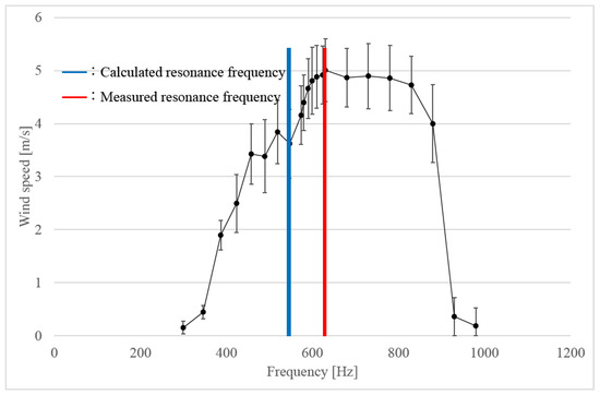
Figure 2.
Wind velocity vs. frequency at 5 mm sound hole.
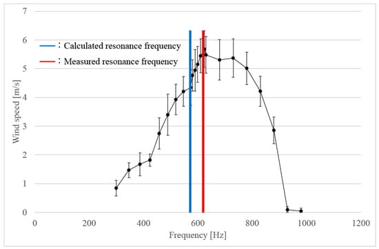
Figure 3.
Wind velocity vs. frequency at 5.5 mm sound hole.
The error bar includes the measurement error inherent in the device. According to the information provided by the manufacturer of the hot-wire anemometer (Testo 405-V1), the measurement accuracy is 0.1 m/s + 5% of measurement value in the velocity range up to 2 m/s and 0.3 m/s + 5% of measurement value in the velocity range over 2 m/s.
The blue line in Figure 2 and Figure 3 shows the calculated resonance frequency, and the red line shows the experimentally measured resonance frequency. As a result of some preliminary experiments, a peak appeared at the beginning of the measurement, and then the air volume tended to decrease. Based on these results, the peak value that appears first was measured twice and averaged to create a graph.
Generally, the wind speed coming out of the Helmholtz resonance is expected to be the fastest at the resonance frequency. However, as a result, there was a difference of about 10% between the calculated resonance frequency and the actual measured value. The main cause is considered to be measurement error due to the installation conditions of the measuring instrument and the environmental conditions that are not considered in Equation (25). The maximum wind speed at 5.5 mm sound hole was about 5.68 m/s, while the maximum wind speed at 5 mm sound hole was about 5.01 m/s.
Since the frequency with the strongest wind deviated slightly from the theoretical resonance frequency, the sound wave with the frequency with the strongest wind was used in the actuator drive experiment. Currently, we assume that the wind is coming out of the hole perpendicular to the ball to create the physical model of the actuator.
The maximum wind speed of 5.5 mm sound hole was faster than that of 5.01 mm sound hole in the entire frequency range. Based on these results, in the following experiments, we decided to use a ping-pong ball with a sound hole of 5.5 mm as a Helmholtz resonator. To clarify the dependency of flow velocity on sound volume, we also show the relation between volume and air volume when the ball hole is 5.5 mm and the air volume is maximum. Figure 4 shows the graph to show the relation between sound volume and wind speed. Data was measured three times each. The graph shows the average value of the measured values and the maximum and minimum values as error bars. As shown in Figure 4, when the volume is low, the wind from the ball is almost zero. On the other hand, when the volume exceeds a certain value (about 110 dBA in this case), the wind speed from the ball increases almost linearly according to the volume.
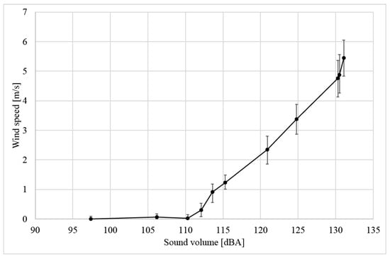
Figure 4.
Relationship between sound volume and wind speed.
5. Sound Driven Actuator
5.1. Physical Characteristics of the Ball as an Actuator
Let us consider physical characteristic of the ball as an actuator. The rotation of the ball depends on the coefficient of static friction with respect to the rotation of the material. Let μ be the coefficient of static friction. The frictional force Fstatic can be written as follows, using the normal force N.
N can be described as follows:
where m is the mass of the actuator. g is the gravitational acceleration. Hence,
On the other hand, the object momentum can be calculated mv [kgm/s] where m and v are the mass and the velocity of the objects, respectively. In the case of fluid, when we assume that the fluid density is ρ [kg/m3], the fluid velocity is v [m/s] and the area of the surface through which the fluid passes is S [m2], the momentum of fluid per Δt [s] is calculated as ρSv2 Δt [Ns]. Hence, the force generated by one ball per unit time f is described as
For example, the area S is 2.38 × 10⁻⁵ [m2] for a hole with a diameter of 5.5 mm. The density of air under normal temperature and pressure is 1.29 [kg/m3]. Hence, the force at the maximum wind speed is theoretically 9.89 × 10⁻⁴ [N]. If f is larger than Fstatic, the actuator can move. Hence, the following formula can be obtained.
The movable weight is constrained as follows:
5.2. Design of the Actuator
This section describes the design of the sound driven actuator. We prepared four types of design to check the movement: a ball with nothing attached (Figure 5), a ball with wheels (Figure 6), a ball with thin cotton swab feet (Figure 7), and a ball with rounded cotton swab feet (Figure 8). We conducted a moving experiment using a ball with a 5.5-mm-diameter hole. A cotton swab was attached to the ball with the aim of reducing the contact point between the ground and the actuator and reducing friction by attaching a rod-shaped object to the actuator.
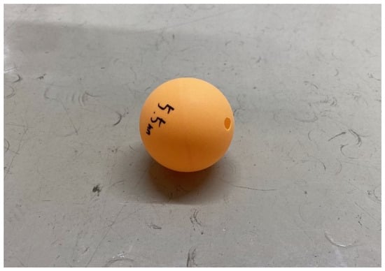
Figure 5.
Appearance of a ball (The diameter of the ball is 44 mm. Its weight is 2.5 g.).
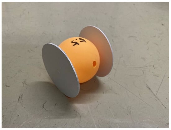
Figure 6.
Appearance of a ball between wheels (The diameter of the ball is 44 mm. The wheel diameter is 54 mm. Its weight is 5.5 g.).
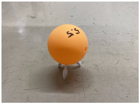
Figure 7.
Appearance of a ball with a fine-tipped cotton swab (The diameter of the ball is 44 mm. The cotton swab length is 20 mm. Its weight is 2.7 g.).
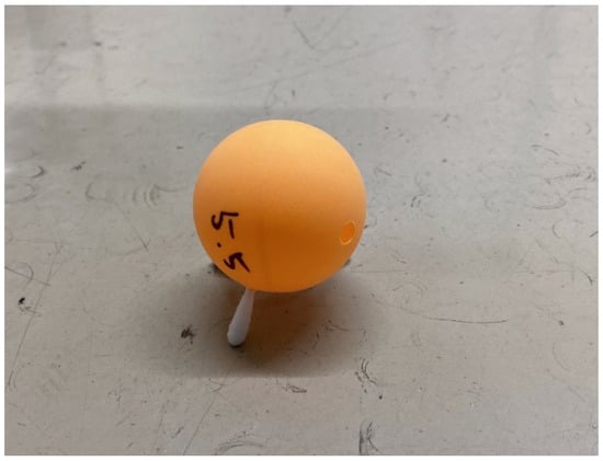
Figure 8.
Appearance of a ball with a round-tipped cotton swab (The diameter of the ball is 44 mm. The cotton swab length is 16 mm. Its weight is 2.7 g.).
The hole on the ball was made using a tabletop drilling machine (K-21 made by Hozan Tool Ind. Co., Ltd. (Osaka, Japan)). The disk that will be the wheel is made of coated cardboard. We cut it by using a circular cutter (iC-1500P made by NT Inc. (Osaka, Japan)) and pasted it to the ball with adhesive. When attaching a cotton swab to the ball, we cut the cotton swab and attach it to the ball with adhesive. The experiment was conducted in an anechoic chamber.
Figure 9 shows the initial setup of the experiments. As shown in Figure 9, we set the actuator on an ABS board. In our study, it is assumed that the ball does not slide on the ABS plate. In other words, we suppose that the actuator moves by rotation and does not slip. As results of the experiment, we think that the assumption is satisfied.
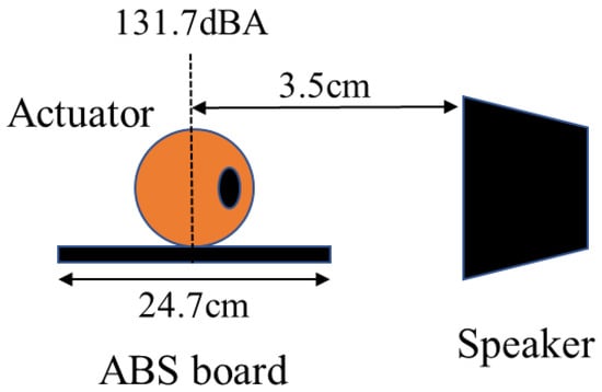
Figure 9.
Experimental setup.
The speaker is first set 3.5 cm apart from the actuator. The speaker used in the experiment is a powered speaker MoniOne made by Classic Pro. The sound volume at the actuator point was 131.7 dBA. The room temperature was 10.4 °C and the maximum wind speed was 6.01 m/s at 730 Hz. The experimental method was to apply a sound of 730 Hz to each of the four structures and observe how they behaved.
5.3. Results of the Migration Experiments
The results of the experiment are shown in Table 1. The ball with a fine-tipped cotton swab and the ball with a round-tipped cotton swab did not move when sound was applied. It is considered that the ball with a cotton swab did not move because the friction at the ground contact point increased.

Table 1.
Behavior of each structure.
Figure 10 shows the actual movements of the ball with nothing attached. As shown in Figure 10, the ball with nothing attached moved. As the ball rotates, the holes move, resulting in reciprocating motion. Figure 11 shows a representation of this situation. The cause of the reciprocating motion is that as the ball rotates, the position of the hole moves in the opposite direction and the direction of the wind is reversed. Figure 12 shows the actual movements of the ball with wheels. As shown in Figure 12, the holes also move, resulting in reciprocating motion. The cause is considered to be the same as for the ball with nothing attached.
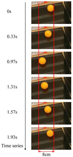
Figure 10.
Actual movement of a ball with nothing attached.
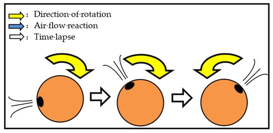
Figure 11.
Change in hole and direction of movement to rotation.
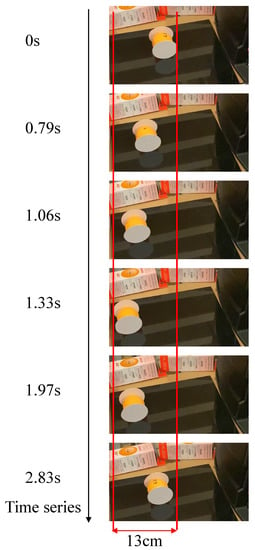
Figure 12.
Actual movement of a ball with wheels.
We examined whether the actuator could be moved forward by controlling the volume. As results of several experiment, it was difficult to move forward. In addition, this approach makes it difficult to move the actuator while accurately grasping the position of the hole when the actuator is located at a remote location. Hence, we redesign the new actuator that can be operated more simply in the next section.
5.4. Redesign of the Actuator
The sound driven actuator was able to move only on the water in the past research, while it succeeded in moving on land in this study. However, the movement was not one-way but a reciprocating motion in the front-back direction. As shown in Figure 11, when the robot moves, the position of the sound hole changes, causing a change in the direction of travel. Hence, it is necessary to improve the actuator so that it can be moved in one direction instead of reciprocating.
Based on the results of the experiments, we redesigned the actuator. Figure 13 shows the design of the improved actuator. In Figure 13, the left figure and right figure show the cross section and side view of the improved actuator, respectively.
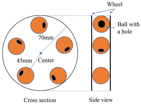
Figure 13.
Design of an improved actuator (The diameter of the ball is 44 mm. The radius of the wheel is 70 mm. The ball was installed at a position 45 mm from the center of the wheel. Its weight is 25.8 g.).
As shown in Figure 13, it includes five balls between two wheels. The holes on the ball are arranged so that they are parallel to the tangential direction of the wheel. It is expected that the arrangement prevents the actuator from reciprocating. The actuator was set on a silicone rubber sheet to reduce the effects of floor vibrations due to sound.
Figure 14 shows the physical model including the supposed wind direction of the five balls of the new actuator and the force due to the winds. In Figure 14, we numbered the ball from 1 to 5 to ease the explanation. fi represents the force acting on the ball i by the wind (i = 1, 2, 3, 4, 5). As shown in Figure 14, all the force from the wind coming out of the actuator works to rotate the disk counterclockwise. Due to the symmetry of the disk, this relationship does not change regardless of the position of the ball. This is the reason why the improved actuator moves forward without reciprocating motion.
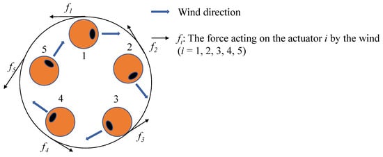
Figure 14.
The force acting on the actuator by the wind.
Figure 15 shows the actual movement of the improved actuator. As shown in Figure 15, it was confirmed that the improved actuator moves straight without reciprocating motion. According to the analysis of the video taken about the improved actuator, the actuator rotated about half a turn in 2.6 s. Considering that the wheel radius of the improved actuator is 7 cm, the speed of movement is estimated to be approximately 8.4 cm/s. It is also noted that we also tried an experiment in which 2, 3, and 4 balls were placed. However, the amount of air coming out of the ball was not enough, and it was not possible to obtain sufficient rotational force.
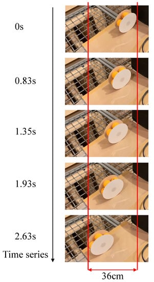
Figure 15.
Movement of an improved actuator.
6. Conclusions
In this study, we introduced sound driven actuators using Helmholtz resonance. We formulated the physics of Helmholtz resonance and showed some designs of actuators. In the migration experiment, we used Helmholtz resonance to conduct an experiment to verify the migration method. Through the first experiments, some of the developed actuators succeeded in moving on land. However, their movement was not one-way but a reciprocating motion in the front-back direction.
Based on the results of the experiments, we improved the actuators. As the results show, it was confirmed that the improved actuator moved straight without reciprocating motion. We could confirm the operation of the sound driven actuator on the ground using Helmholtz resonance on an experimental basis. However, it is still difficult to control the operation direction of the actuator.
For future works, we would like to control the direction of the actuator by using the difference in resonance frequency depending on the size of the hole or ball. We also would like to develop a robot that can repair cracks by using the developed actuator as a drive source for the robot.
Author Contributions
Conceptualization, T.N. and M.M.; methodology, T.N.; validation, T.N.; investigation, T.N. and M.M.; writing—original draft preparation, T.N.; writing—review and editing, M.M.; supervision, M.M.; project administration, M.M.; funding acquisition, M.M. All authors have read and agreed to the published version of the manuscript.
Funding
This research was supported by JSPS KAKENHI Grant Number JP20H02412 and JP20K21020.
Institutional Review Board Statement
Not applicable.
Informed Consent Statement
Not applicable.
Conflicts of Interest
The authors declare no conflict of interest.
References
- Gregory, J. Application of Multi-Robot Systems to Disaster-Relief Scenarios with Limited Communication. Field Serv. Robot. 2016, 113, 639–653. [Google Scholar]
- Kamegawa, T.; Akiyama, T.; Sakai, S.; Fujii, K.; Une, K.; Ou, E.; Matsumura, Y.; Kishutani, T.; Nose, E.; Yoshizaki, Y.; et al. Development of a separable search-and-rescue robot composed of a mobile robot and a snake robot. Adv. Robot. 2020, 34, 132–139. [Google Scholar] [CrossRef]
- Deng, W.; Huang, K.; Chen, X.; Zhou, Z.; Shi, C.; Guo, R.; Zhang, H. Semantic RGB-D SLAM for Rescue Robot Navigation. IEEE Access 2020, 8, 221320–221329. [Google Scholar] [CrossRef]
- ANNnewsCH, “[Nuclear Power] Domestic Robot Left Behind in Reactor Building (11/10/21)”. Available online: https://www.youtube.com/watch?v=9AV4i6-2Q4s (accessed on 14 March 2022).
- Kawauchi, N.; Shiotani, S.; Kanazawa, H.; Sasaki, T.; Tsuji, H. A plant maintenance humanoid robot system. In Proceedings of the IEEE International Conference on Robotics and Automation, Taipei, Taiwan, 14–19 September 2003; pp. 2973–2978. [Google Scholar]
- Shibata, T.; Sasaya, T.; Kawahara, N. Development of In-Pipe Microrobot Using Microwave Energy Transmission. Electron. Commun. Jpn. 2000, 84, 1–8. [Google Scholar] [CrossRef]
- Huruta, T.; Yoshida, T.; Nishimura, T.; Yamato, H. Development of the Exploring Robot toward Future Indoor Surveillance Missions in the Fukushima Daiichi Nuclear Power Plant. J. Robot. Soc. Jpn. 2014, 32, 92–97. [Google Scholar]
- Onishi, K.; Onishi, N.; Fujita, J.; Hara, K.; Hashimoto, T. Design and Development of Robots which Support Activities of Recovery from Nuclear Hazards. J. Robot. Soc. Jpn. 2014, 32, 816–824. [Google Scholar] [CrossRef][Green Version]
- Nagatani, K.; Kiribayashi, S.; Okada, Y.; Otake, K.; Yoshida, K.; Tadokoro, S.; Nishimura, T.; Yoshida, T.; Koyanag, E.; Fukushima, M.; et al. Emergency response to the nuclear accident at the Fukushima Daiichi Nuclear Power Plants using mobile rescue robots. J. Field Robot. 2013, 30, 44–63. [Google Scholar] [CrossRef]
- Tsiligiannis, G.; Touboul, A.; Bricas, G.; Maraine, T.; Boch, J.; Wrobel, F.; Michez, A.; Saigne, F.; Godot, A.; Etile, A.; et al. Evaluation and Analysis of Technologies for Robotic Platforms for the Nuclear Decommissioning. In Proceedings of the 15th International Conference on Design and Technology of Integrated Systems in Nanoscale Era, Marrakech, Morocco, 1–3 April 2020. [Google Scholar]
- Han, Z.; Duan, X.; Wang, Y.; Pan, Y.; Wu, Y. Robot System and Fastening Force Control for Sealing Blocking Plates of Steam Generator. In Proceedings of the 9th IEEE International Conference on CYBER Technology in Automation, Control, and Intelligent Systems, Suzhou, China, 29 July–2 August 2019. [Google Scholar]
- Nagatani, K.; Kiribayashi, S.; Okada, Y.; Tadokoro, S.; Nishimura, T.; Yoshida, T.; Koyanagi, E.; Hada, Y. Redesign of rescue mobile robot Quince. In Proceedings of the 2011 IEEE International Symposium on Safety, Security and Rescue Robotics, Kyoto, Japan, 1–5 November 2011. [Google Scholar]
- Dong, P.; Wang, X.; Xing, H.; Liu, Y.; Zhang, M. Design and control of a tracked robot for search and rescue in nuclear power plant. In Proceedings of the 2016 International Conference on Advanced Robotics and Mechatronics, Macau, China, 18–20 August 2016. [Google Scholar]
- Zolfagharian, A.; Durran, L.; Gharaie, S.; Rolfe, B.; Kaynak, A.; Bodaghi, M. 4D printing soft robots guided by machine learning and finite element models. Sens. Actuators A Phys. 2021, 328, 112774. [Google Scholar] [CrossRef]
- Wang, Z.; Hirai, S. Analytical Modeling of a Soft Pneu-Net Actuator Subjected to Planar Tip Contact. IEEE Trans. Robot. 2022, 1–14. [Google Scholar] [CrossRef]
- Zolfagharian, A.; Mahmud, M.A.P.; Gharaie, S.; Bodaghi, M.; Kouzani, A.Z.; Kaynak, A. 3D/4D-printed bending-type soft pneumatic actuators: Fabrication, modelling, and control. Virtual Phys. Prototyp. 2020, 15, 373–402. [Google Scholar] [CrossRef]
- Hawkes, E.W.; Blumenschein, L.H.; Greer, J.D.; Okamura, A.M. A soft robot that navigates its environment through growth. Sci. Robot. 2017, 2, eaan3028. [Google Scholar] [CrossRef] [PubMed]
- Nishikawa, Y.; Matsumoto, M. Lightweight indestructible soft robot. IEEJ Trans. Electr. Electron. Eng. 2018, 13, 652–653. [Google Scholar] [CrossRef]
- Tondu, B.; Lopez, P. Modeling and control of McKibben artificial muscle robot actuators. IEEE Control Syst. 2000, 20, 15–38. [Google Scholar] [CrossRef]
- Tondu, B. Modelling of the McKibben artificial muscle: A review. J. Intell. Mater. Syst. Struct. 2012, 23, 225–253. [Google Scholar] [CrossRef]
- Boxerbaum, A.; Chiel, H.J.; Quinn, R.D. A New Theory and Methods for Creating Peristaltic Motion in a Robotic Platform. In Proceedings of the IEEE International Conference on Robotics and Automation, Anchorage, AK, USA, 3–8 May 2010; pp. 1221–1227. [Google Scholar] [CrossRef]
- Rosendo, A.; Nakatsu, S.; Narioka, K.; Hosoda, K.; Pneupard, A. biomimetic musculoskeletal approach for a feline-inspired quadruped robot. In Proceedings of the IEEE/RSJ International Conference on Intelligent Robots and Systems, Tokyo, Japan, 3–7 November 2013; pp. 1452–1457. [Google Scholar] [CrossRef]
- Niiyama, R.; Nagakubo, A.; Kuniyoshi, Y.; Mowgli, A. Bipedal Jumping and Landing Robot with an Artificial Musculoskeletal System. In Proceedings of the IEEE/RSJ International Conference on Intelligent Robots and Systems, Rome, Italy, 10–14 April 2007; pp. 2546–2551. [Google Scholar] [CrossRef]
- Niiyama, R.; Nishikawa, S.; Kuniyoshi, Y. Athlete Robot with Applied Human Muscle Activation Patterns for Bipedal Running. In Proceedings of the IEEE-RAS International Conference on Humanoid Robots, Nashville, TN, USA, 6–8 December 2010; pp. 498–503. [Google Scholar] [CrossRef]
- Norioka, K.; Hosoda, K. Motor Development of an Pneumatic Musculoskeletal Infant Robot. In Proceedings of the IEEE International Conference on Robotics and Automation, Shanghai, China, 9–13 May 2011; pp. 963–968. [Google Scholar] [CrossRef]
- Steltz, E.; Mozeika, A.; Rodenberg, N.; Brown, E.; Jaeger, H.M. JSEL: Jamming Skin Enabled Locomotion. In Proceedings of the IEEE/RSJ International Conference on Intelligent Robots and Systems, St. Louis, MO, USA, 11–15 October 2009; pp. 5672–5677. [Google Scholar] [CrossRef]
- Shepherd, R.F.; Ilievski, F.; Choi, W.; Morin, S.A.; Stokes, A.A.; Mazzeo, A.D.; Chen, X.; Wang, M.; Whitesides, G.M. Multigait soft robot. Proc. Natl. Acad. Sci. USA 2011, 108, 20400–20403. [Google Scholar] [CrossRef]
- Li, S.; Daniel, M.V.; Rus, D.; Wood, R.J. Fluid-driven origami-inspired artificial muscles. Proc. Natl. Acad. Sci. USA 2017, 114, 13132–13137. [Google Scholar] [CrossRef]
- Yamagiwa, K.; Katoh, M.; Yoshida, M.; Ohkawa, A.; Ichijo, H. Temperature-Swing Column Adsorption of Nonionic Surfactant with Poly(vinylmethylether) Gel. J. Chem. Eng. Jpn. 2001, 34, 1317–1320. [Google Scholar] [CrossRef]
- Kim, Y.S.; Liu, M.; Ishida, Y.; Ebina, Y.; Osada, M.; Sasaki, T.; Hikima, T.; Takata, M.; Aida, T. Thermoresponsive actuation enabled by permittivity switching in an electrostatically anisotropic hydrogel. Nat. Mater. 2015, 14, 1002–1007. [Google Scholar] [CrossRef]
- Brannon-Peppas, L.; Peppas, N.A. Dynamic and equilibrium swelling behaviour of pH-sensitive hydrogels containing 2-hydroxyethyl methacrylate. Biomaterials 1990, 11, 635–644. [Google Scholar] [CrossRef]
- Fundueanu, G.; Constantin, M.; Bucatariu, S.; Ascenzi, P. pH/thermo-responsive poly(N-isopropylacrylamide-co-maleic acid) hydrogel with a sensor and an actuator for biomedical applications. Polymer 2017, 110, 177–186. [Google Scholar] [CrossRef]
- Osada, Y.; Okazaki, H.; Hori, H. A polymer gel with electrically driven mobility. Nature 1992, 355, 242–244. [Google Scholar] [CrossRef]
- Matsumoto, M. Water driven soft actuator. Appl. Syst. Innov. 2018, 1, 41. [Google Scholar] [CrossRef]
- Yu, Y.; Nakano, M.; Ikeda, T. Photomechanics: Directed bending of a polymer film by light. Nature 2003, 425, 145. [Google Scholar] [CrossRef] [PubMed]
- Otake, S.; Matsumoto, M. Investigation of driving principle of non-electrically driven robots using sound waves as a power source. In Proceedings of the 2021 IEEE International Conference on Mechatronics and Automation, Online, 8–11 August 2021; pp. 1261–1267. [Google Scholar]
- Helmholtz, H. On the Sensations of Tone as a Physiological Basis for the Theory of Music. Nature 1875, 12, 449–452. [Google Scholar]
- Fletcher, N.H.; Rossing, T.D. The Physics of Musical Instruments; Springer: Berlin/Heidelberg, Germany, 1998. [Google Scholar]
- Greene, C.A.; Argoiv, T.F.; Wilson, P.S. A Helmholtz resonator experiment for the Listen Up project. J. Acoust. Soc. Am. 2009, 5, 025001. [Google Scholar]
- Raichel, D.R. The Science and Applications of Acoustics; Springer: Berlin/Heidelberg, Germany, 2006; pp. 145–149. [Google Scholar]
Publisher’s Note: MDPI stays neutral with regard to jurisdictional claims in published maps and institutional affiliations. |
© 2022 by the authors. Licensee MDPI, Basel, Switzerland. This article is an open access article distributed under the terms and conditions of the Creative Commons Attribution (CC BY) license (https://creativecommons.org/licenses/by/4.0/).