Abstract
In this paper, an opposing jet is applied to the space shuttle arc leading edge and the lifting body cone leading edge in the hypersonic condition of the rarefied flow field. The DSMC numerical algorithm is used to simulate and analyze the underlying working physics of the opposing jet. The results provide a reference for designing hypersonic vehicles in near space that reduce drag and protect against heat.
1. Introduction
Higher altitudes and faster flight speeds have increasingly attracted more attention with scientists regarding the development of hypersonic vehicles. The higher the speed, the greater friction, total pressure, and heat flux are caused in the windward area of the aircraft. This will affect the aircraft performance with regards to mobility. In addition, the increase of aircraft flight altitude will cause an increase in the degree of air rarefaction. The air density of the incoming flow decreases and results in a discontinuous influence. These challenging physical conditions are also faced by the scientists who explore outer space galaxies, such as spacecraft reentry into the atmosphere and satellite recycling. The aircrafts usually fly at high speed and experience extreme resistance and thermal effect especially in the middle layer of the atmosphere when they return from the universe to the earth. This explains their severe deformation and damage after successfully returning to earth. This damage threatens the safety and stability of the aircraft. The cost of maintenance is very high as well for reuse purposes. Therefore, it is essential to reduce the heat effect and resistance when flying aircrafts in the rarefied flow field.
It has been studied that maximum heat flux and resistance usually occur at the flow stagnation area of the aircraft. When a large amount of high-speed air flow reaches the wall, the kinetic energy in the flow is consequently converted to heat and internal energy. The bow shock wave or conical shock wave are formed in the flow field. There are three methods to minimize the consequent heat damage to the aircraft. The first one is to apply thermal protection or mitigate heat, such as applying a thermal insulation structure, heat pipe dredging, etc. [1,2,3]. This method requires practical experimental verification. It has a high requirement for the material and is very costly. Additionally, it is challenging to simulate the rarefied flow condition. The second method is to modify the shape structure of the aircraft, such as applying windward cavity, pneumatic rod, etc. [4,5,6]. This method may weaken the advantages of the original aircraft and degrade the performance of the aircraft in order to reduce resistance and heat flux. The last method is to shoot high-pressure and low-temperature jets [7] from the nozzle opposite to the incoming flow direction, namely the opposing jet method. This active control method will change the shock structure, and enforce the change of the air flow trajectory to reduce heat flux and resistance. This method can meet long flight period requirements for hypersonic vehicles. It does not need to transform the aircraft shape, which is designed purposely with high lift and drag ratio. Furthermore, other drag reduction and heat protection methods can be coupled. Both stability requirements and cooling and drag reduction can be improved simultaneously. The opposing jet method is practically applicable and has a certain research basis, so the present paper will study and verify this method through numerical simulation.
The conventional opposing jet technology is mainly concerned with the continuous flow gas environment and vehicles mostly flying at low altitudes. However, as aircraft altitude increases, the atmospheric environmental density decreases and the gas rarefaction effect becomes apparent. The continuum assumption of the N-S equation does not apply to rarefied flow because of the discontinuous effect of airflow. Researchers have found that the DSMC method is a reasonable numerical simulation algorithm for accurately calculating the rarefied flow field [8].
The DSMC method has many applications and much research in jets. Hui Wang [9] proposed a comprehensive model that couples direct simulation Monte Carlo (DSMC) method with the finite difference method to study the heat transfer caused by moving rarefied hydrogen jet impingement. The results show that the average convective heat transfer coefficient of jet impingement is positively correlated with inlet pressure and jet aperture, but negatively correlated with impingement distance. Mishra S. K. [10] investigated the disturbance to the lunar surface caused by the jet plume from the thruster exhaust, and direct simulation Monte Carlo (DSMC) solvers were used to analyze plume dynamics and plume gas interactions with in situ lunar soil, concluding that whereas the disturbance and damage caused by a small lander appears to be minimal, a large lander and a landing near an early landing site would pose a significant threat to existing hardware. Virgile C. [11] uses hybrid Navier-Stokes (NS) and direct simulation Monte Carlo (DSMC) and a unidirectional coupling strategy to simulate a steady-state cold nitrogen flow from a high-pressure millimeter nozzle extended into vacuum, a method that fits well with the data available for microthrusters and whose optimization can significantly reduce computational costs. Z. Cao [12] has developed open source code in OpenFOAM for providing two-phase thinning flow solutions that can generate steady-state and transient results for arbitrary 2D/3D two-phase thinning flows, and has tested converging nozzles that generate solid particle beams, with results that closely match the available analytical and experimental data. Cao Z. [13] uses a direct simulation Monte Carlo method and compressible Navier-Stokes equations to give numerical results on the formation of vortex rings by an excitation wave bypassing a nearly 90° angle under appropriate Maxwell velocity slip and von Smoluchowski temperature jump boundary conditions. The effects of the Mach number and thinning effects on the formation and evolution of vortex rings are discussed. Agir M. B. [14] used a direct simulation Monte Carlo method using the dsmcFoam + code for the acoustic nozzle simulation matrix. It was concluded that for a single nozzle, increasing the stagnation temperature has no significant effect on the normalized surface pressure, but increases the maximum normalized shear stress and increases the measured heat flow over the surface. For two-nozzle and four-nozzle arrays, the number of nozzles has a much greater effect on the measured surface properties than the stagnation temperature.
Studies on reducing drag and protecting the engine from heat have been conducted in recent years using opposing jets. Wang Z. and X. Zhang [15] have numerically analyzed the flow field mechanism of a supersonic opposing jet bluff body model in a supersonic flow field. It shows that a single pressure parameter can control the formation of supersonic opposing jets and can form either a long or short penetration mode. Controlling opposite jet parameters is an effective way of achieving thermal protection and reducing the drag of bluff body structures. Lmen S. [16] examined the effect of jet on reducing rocket resistance and heat load, studied the effect of jet emitted from the head of rocket on the opposite direction of incident free flow, and successfully reduced the area average surface temperature and resistance by 52% and 22%, respectively. Eghlima Z. [17] studied the flow field around the hemispherical column with a new combination of spike jet and opposing jet under the free flow condition of Mach 6. For the actual model, the drag coefficient is significantly reduced by about 86–90%, compared to the spherical cylinder model without jet and spike. Bsa B. et al. [18] studied the heat transfer changes and shock properties around the blunt body by combining cylindrical and parabolic cavity geometries with opposing jets, and found that the parabolic cavity with an opposing jet had a reduction of about 33% of surface heat flow and 43% of flow oscillation. Shen B.X. et al. [19] investigated the drag reduction efficiency and heat flux reduction efficiency of a unit mass opposing jet, and found that a higher jet temperature strengthens the drag reduction efficiency, but has the least impact on it. The heat flux reduction efficiency is affected by jet temperature and pressure. Fan W.J. et al. [20] studied the effects of jet total pressure ratio, angles of attack, and the free flow Mach number on the drag and heat reduction through the numerical simulation of porous opposing jets, and demonstrated that the greater the jet total pressure ratio, the better the performance of drag and heat reduction. It can be seen from the above literature that the application of an opposing jet in the continuous flow region has a good effect on drag reduction and heat prevention, and has good adaptability under hypersonic conditions. In the rarefied flow region, the research on an opposing jet started late due to the limitation of numerical algorithm, and the results are fewer. Wenqing Zhang [21] studied the hypersonic flow field of a 2.6% Apollo single jet and combined jet with a Mach number of 19 and height of 60 km, and studied the heat and drag reduction mechanism of single and combined opposing jets at different flow rates. The opposing jet technology in the rarefied flow region is studied, and the open source platform is used for numerical simulation. It is proven that the combined an opposing jet also has the effect of cooling and drag reduction in the rarefied flow region, which provides a reference for subsequent research.
Although the DSMC method is widely used in jets, most of it studies micro-scale jet flow in still space. However, the research on opposing jets still focuses on the continuous flow region, and the research on rarefied flow field is still lacking. With the rapid development of hypersonic vehicles, the research on cooling and drag reduction in a rarefied flow field is very necessary and meaningful. Therefore, this paper mainly studies the cooling and drag reduction effect of the opposing jet in the rarefied flow field, and focuses on the rarefied altitude, about 70 km~80 km, takes PR as the variable, and explores the cooling and drag reduction effect of aircraft with different pressure ratios and the sensitivity of the leading edge of aircraft with different shapes to the pressure ratio so as to provide a reliable basis for the subsequent cooling and drag reduction research of a hypersonic rarefied flow field.
2. Opposing Jet Principle
As aforementioned, the opposing jet technology relies on injecting air flow from the nozzle pre-installed on the aircraft to change the speed and direction of incoming flow and structures of shock waves. An opposing jet structure, such as jet terminal shock, free stagnation point, and recirculation regions, is shown in Figure 1 [22]. The high-pressure gas in the nozzle is ejected from the nozzle to form a high-speed jet in front of the stagnation point of the aircraft, and interacts with the incoming flow to change the original shock structure. Mach number, total pressure, total temperature, flowing medium, and total pressure ratio (PR) are the major parameters affecting incoming flow and jets. PR represents the ratio of total pressure of the jet to total pressure of incoming flow. There are three shock modes under the influence of the jet: blunt penetration mode, long penetration mode, and short penetration mode [23,24,25]. The key to the change of opposing jet structures is the ratio of nozzle outlet pressure (PJ) to ambient static pressure (P0). When PJ = 0, there is no opposing jet, and the flow field appears as a conventional detached bow shock. When the opposing jet begins to increase(PJ < P0), the jet is in the over-expanded condition, and the expansion is limited. It is compressed by the jet boundary and causes the emergence of compression waves. At this time, the jet begins to interfere with the flow structure, and a small amount of jet penetrates the shock wave; then, the impact point of the jet is in the flow deceleration zone, resulting in flow instability, and the flow field is in the blunt penetration mode. When PJ is slightly greater than P0, the jet is in the slightly under-expanded condition, so the jet can expand further, and the flow penetrating the shock wave is more. The free jet boundary compresses and reflects the expanded jet to form an incident shock wave. Then, these incident shock waves take the jet axis as the axis of symmetry and reflect multiple times to form a divergent diamond-shaped shock wave. Because the under-expanded jet will lead to the instability of the flow field, the slightly under-expanded jet adjusts itself, ending the impact point of the normal jet in the flow acceleration region, greatly increasing the separation distance of the bow shock wave and forming a weak bow shock. This flow field structure is called long penetration mode. When PJ further increases (PJ >> P0), the jet is in a high under-expanded condition, a large number of jets penetrate the shock wave, the bow shock wave structure collapses, the jet carries out Prandtl–Meyer expansion, and a Mach disk is formed at the balance between the jet pressure and the ambient pressure. The Mach disk sharply reduces the jet velocity and pressure and makes the jet flow quickly to reach equilibrium with the environment. Because this normal impact is in the jet acceleration zone, the high under-expanded jet terminates at the Mach disk, so the flow field shows high stability and has a short stagnation distance and shock wave detachment distance. This flow field structure is called short penetration mode. In general, with the increase of the PJ/P0 ratio, the opposing jet field will change from unstable blunt penetration mode to unstable LPM, and then quickly change to SPM with a stable structure similar to that without an opposing jet flow field, as shown in Figure 2 [25]. The jet boundary collapses when the jet meets high-speed incoming flow; then, the jet is separated and reattached to the aircraft wall to form a recirculation region, which appears as a vortex between the Mach disk and the leading edge of the aircraft as shown in Figure 1b.
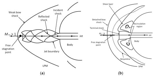
Figure 1.
Schematic diagram of opposing jet structure: (a) Long penetration mode; (b) Short penetration mode.
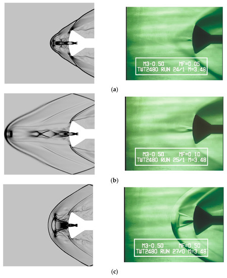
Figure 2.
Experimental diagram of opposing jet structure: (a) Blunt penetration mode; (b) Long penetration mode; (c) Short penetration mode.
3. Numerical Approach
3.1. DSMC Method
Direct simulation of Monte Carlo (DSMC) is a molecular dynamics method [26]. At present, it is mainly used for simulating rarefied flow fields. The key idea is to replace real molecules with limited simulated molecules, analyze the change process of flow field by simulating molecular motion and collision, and reduce the error caused by molecular information fluctuation by collecting a large amounts of statistical samples, which in turn yield all the macroscopic characteristics of the flow field (Mach number, pressure coefficient, friction coefficient, heat flow, etc.) based on the statistics.
The calculation of the DSMC method is divided into three steps: molecular motion, molecular collision, and molecular sampling. Molecular motion uses a combination of area element/volume element search technology and the ADT (alternative digital tree). Calculate the molecular trajectory and determine whether a molecule intersects the grid edge and whether the intersecting edge is the flow field boundary. The program will update the molecular information if the molecule only intersects with the internal grid edges. Otherwise, it will judge the boundary type if the molecule intersects the boundary. In general, the molecules are deleted directly if the intersection boundary is the far field flow boundary or the inlet/outlet boundary. When the intersection boundary is symmetrical, the mirror reflection will be adopted, and the molecules’ tangential velocity remains the same, but the normal phase velocity will be reversed. When the intersection boundary is a nonslip boundary (wall), the diffuse reflection will be utilized, in which the molecules’ velocity is distributed randomly and reflected.
The molecular collision is usually calculated using mature collision models, such as variable diameter hard sphere model (VHS), variable diameter soft sphere model (VSS), generalized hard sphere model (GHS), etc. A pair of the colliding molecules are treated as two spheres to do elastic collision, as shown in Figure 3. The collision cross section , viscous collision cross section , diffusion collision cross section , and deflection angle are calculated. The ratio between and is almost stable, because the single component gas is used in this paper, and the diffusion effect in multi-component gas mixture caused by the asymmetry of gas molecular scattering does not need to be considered. Under the comprehensive consideration, the VHS model has good calculation efficiency and accuracy; therefore, the VHS model will be adopted, and the main formulae are expressed as follows:
where is the aiming distance, is the molecular diameter depending on the temperature changes in VHS model, is the viscosity coefficient, is the power of the plane kinetic energy on which depends, subscript is the reference value when the relative velocity is , , is the Boltzmann constant, and is the molecular mass.
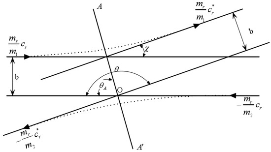
Figure 3.
Schematic diagram of molecular collision.
The Monte Carlo method is used for statistics of molecular sampling. In order to eliminate the numerical oscillation caused from the randomness, more time steps are taken for analyzing, and the averaged value is used as the corresponding flow state. In this way, the flow field is gradually updated during numerical iteration until convergence is achieved.
In the DSMC method, far-field and inlet conditions are usually set as the static pressure and temperature, whereas the opposing jet conditions are usually set as the total pressure, total temperature, and total pressure ratio as well. The flow medium is generally treated as the compressible gas in rarefied flow field. The ratios between total pressure and static pressure and between total temperature and static temperature are expressed as follows:
where is the Mach number and is specific heat ratio.
3.2. Code Valiation
In this paper, the self-developed unstructured grid DSMC program is used to simulate and analyze the application of opposing jet. In order to verify the accuracy and reliability of the program, the hypersonic rarefied flow experimental data of compression corner in reference [27] are used for numerical verification, and the grid independence is verified at the same time. It is proven that this program can become a numerical simulation method for subsequent research.
The calculation model is shown in Figure 4. The simulated gas is pure nitrogen, kn = 0.0066, the number of simulated molecules is 3.45 million, grid1 = 467,653, grid2 = 1,082,762, grid3 = 1,540,397, the total time step is 100,000, time step Δt = 5 × 10⁻⁸ s, incoming flow density ρ∞ = 5.14 × 10⁻⁵, velocity V∞ = 1340 m/s, temperature T∞ = 8.3 K, and wall temperature TW = 383 K.

Figure 4.
Two-dimensional ramp model (β = 35°).
Figure 5 shows the contour of density, temperature, and pressure. Figure 6 shows the comparison of pressure coefficient CP and friction coefficient Cf with the experimental results in the literature [27]. It can be seen that the calculated results of different grid densities are in good agreement with the experimental data, and the error is within the acceptable range. This result is consistent with the actual situation. Therefore, the DSMC program used in this paper has accuracy and reliability, and can be applied to the study of opposing jets in the rarefied flow field.
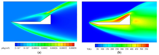
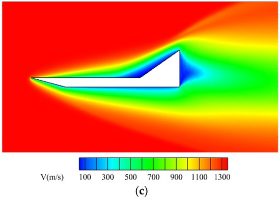
Figure 5.
The contour of two-dimensional ramp model (β = 35°): (a) Density; (b) Temperature; (c) Velocity.
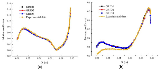
Figure 6.
Wall coefficient distribution: (a) Friction coefficient; (b) Pressure coefficient.
4. Numerical Example
In this paper, the numerical simulation on the opposing jet is performed for the double ellipsoid and the pointed cone structures of the space shuttle. It is assumed that the media of the incoming flow are constant. The working conditions are defined according to the practical engineering application. The effects of the opposing jet flow on the original shock structure, resistance, and heat flux of the model are explored.
The pressure coefficient, friction coefficient, and Stanton number are used to characterize the resistance and heat flow on the wall. They are defined as follows:
- (1)
- Stanton number
is the adiabatic wall temperature,
where is Prandtl number.
is heat flux, and it is the net energy flux of the molecules hitting the solid wall surface. The flux is positive if its direction is the positive normal direction of the solid wall. It depends on the translational energy, rotational energy, and vibration energy of the incident particles. It is defined as:
where is the number of real molecules contained in the simulated ones, is the unit surface area, is the number of molecules hitting the solid wall in each time step, is the Kinetic energy, and and are the molecular rotational energy and molecular vibrational energy. The vibration energy mode cannot be triggered due to the low temperature of the flow field, and the molecular vibration energy is not considered here.
- (2)
- Pressure coefficient
- (3)
- Friction coefficient
4.1. Numerical Simulation of Opposing Jet Double Ellipsoid
The double ellipsoid structure geometry and the generated mesh are shown in Figure 7 and Figure 8. The leading edge of the space shuttle head consists of two ellipsoids. The far-field Mach number is , the far-field total pressure is , and the far-field total temperature is . The leading edge of the double ellipsoid is the nozzle outlet with a diameter of 4 mm. The Mach number of the jet is , the total pressure of the jet is , and the total temperature of the jet is . In this paper, the flight altitude is 80 km high. The inflow and jet medium are nitrogen. Figure 9 shows the curve of the curvature radius of the leading edge of the double ellipsoid along the x-axis coordinate. Select the appropriate curvature radius to calculate the Knudsen number, and the minimum value of kn = 7.8 × 10⁻³, the nozzle is a pressure outlet, the wall is a nonslip constant temperature boundary condition, and the temperature is 295 K. The total number of computational grid elements is 1,126,352. The leading edge is locally encrypted because of the high-density of the air on the aircraft leading edge. In the unstructured grid DSMC method, the grid is mainly used to sample the flow field properties. If the selection of molecular collision pairs is carried out on the computational grid at the same time, the dimension of the computational grid must be small enough to ensure that the grid scale is less than one-third of the average free path of local gas molecules. In this way, the number of computational grids is bound to be too large, so that the calculation time is too long. Moreover, in the process of unstructured grid generation, due to the unstructured characteristics of grid nodes, it cannot ensure that each grid element is small enough. In order to get reasonable and correct collision pairs, this paper adds the idea of a sub grid into an unstructured grid. In the selection of collision pairs, it is first considered to be carried out in the same sub grid under the same grid unit. If the collision requirements are not met in the same sub grid, it is selected in the adjacent sub grid. In this way, not only can the correct collision pair be obtained, but also the requirement of grid scale can be reduced. Therefore, the size of the grid near the wall can be less than the average free path of the jet molecules at most. The specific boundary conditions applied are shown in Table 1.
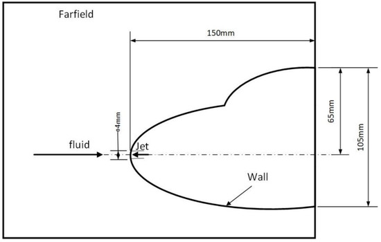
Figure 7.
Schematic view of the double ellipsoid structure.
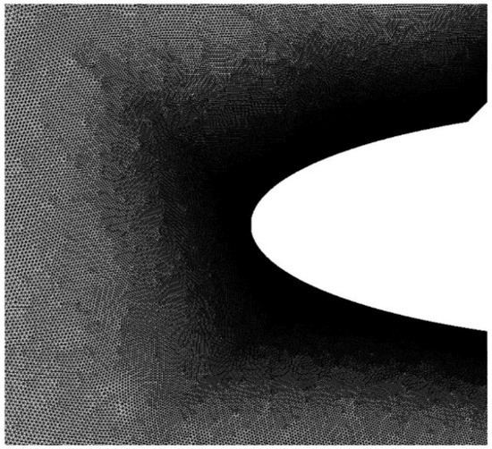
Figure 8.
Double ellipsoid mesh diagram (part).
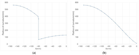
Figure 9.
Radius of curvature: (a) Upper surface; (b) Lower surface.

Table 1.
Boundary condition.
Figure 10a shows the contours of the density distribution and streamline around the double ellipsoid without the opposing jet applied. Figure 10b–e are numerical results when the total pressure ratio of the opposing jet is 0.2, 0.4, 0.6, and 0.8. The Mach disk, recirculation region, and double shock caused by opposing jet are visible. In the rarefied flow field, the opposing jet effect (Mach disk, recirculation region, etc.) is more obvious than that of the continuous flow. In the region with low air density, the molecular interaction force is weak, and the total pressure generated by high Mach number is much greater than the far-field pressure. After a large number of high-density jet molecules enter the flow field, they are less affected by the collision of far-field incoming molecules, and the collision frequency between molecules is low, so the influence range of jet is larger in the rarefied flow field.
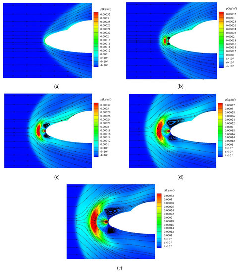
Figure 10.
Contours of density distribution and streamline around the double ellipsoid opposing jet: (a) No opposing jet; (b) PR = 0.2; (c) PR = 0.4; (d) PR = 0.6; (e) PR = 0.8.
The comparison between the cloud images of different total pressure ratios shows that the Mach disk range continues to increase with the increase of PR. The Mach disk and arc shock wave are pushed farther away from the leading edge. The pressure difference between the far-field incoming flow and the jet becomes more apparent when the flow jet density increased. The incoming flow affects the jet insignificantly, and the jet molecules can diffuse to a farther distance to form the Mach disk. Therefore, the Mach disk gradually expands and becomes larger with the increase of PR. The arc shock is also pushed further by the Mach disk.
The eddy current range and intensity in the recirculation region also gradually increase with the increase of PR. The center of the eddy current gradually shifts downstream with the increase of PR. The separation and reattachment points of the eddy current also move downstream. After the jet pressure increases, more jet molecules velocity direction changes to opposite, and the jet molecules with higher density also diffuse further while the density near the wall is still very low. Therefore, the jet starts to move towards the wall and finally reattaches to the wall to form a larger vortex. According to the definition of separation and reattachment points, the positions of separation and reattachment points on the wall under different jet states are calculated. It is found that the separation points are basically located at the nozzle exit. However, with the increase of PR, the reattachment point moves along the wall to the downstream of the incoming flow. Figure 11 shows the curve of reattachment points position.
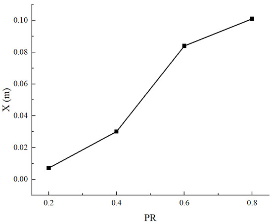
Figure 11.
Position of reattachment point.
Figure 12 shows the distribution of the pressure coefficient, friction coefficient, and the Stanton number on the wall of the double ellipsoid. Each case has two curves representing the upper and lower surfaces, respectively. It shows that the coefficient distribution of the upper surface is slightly higher than that of the lower surface. The upper surface of the double ellipsoid is greatly affected by the resistance and heat flux. The gradient change of the upper surface model is more intense than that of the lower surface. The flow field around the irregular model is more complex, and the change range of momentum and energy before and after the molecule collides with the wall is greater.
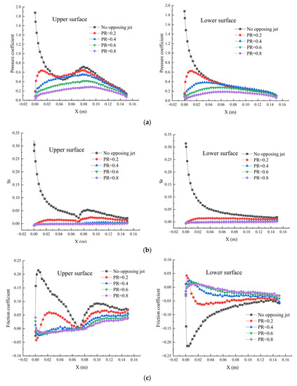
Figure 12.
Double ellipsoid wall coefficient distribution: (a) Stanton number; (b) Pressure coefficient; (c) Friction coefficient.
The incoming gas impacts on the double ellipsoid surface and forms an arc shock wave when no opposing jet is applied. At the stagnation point of double ellipsoid, the Stanton number, pressure coefficient, and friction coefficient reach the highest values. When PR = 0.2, the opposing jet is added into the flow field, and Mach disk and vortex appear in the flow field. The high-speed incoming flow is far away from the wall because of the influence of the jet, and instead the jet opposite to the original flow is affected by the incoming flow and attached to the wall. In addition, some jet separation and reattachment form a recirculation region, and eddies are generated on the wall. Due to the influence of eddy dissipation, the molecular kinetic energy and internal energy of molecules passing through the eddy are greatly reduced, and a relatively stable area is generated near the wall. The kinetic energy difference and momentum difference before and after the molecules collide with the wall become smaller, so the wall coefficient near the recirculation region decreases significantly, whereas the wall coefficient far away from the recirculation region gradually tends to be consistent between the cases with that without opposing jet. As PR increases to 0.4, 0.6, and 0.8, all coefficients are in a downward trend with the increase of PR. It is attributed to the increase of the recirculation region range when PR increases. The eddy current intensity increases which results in the influence range becoming wider and thus the molecular energy and momentum are dissipated and more severe. Therefore, the coefficients are reduced to the lowest value at PR = 0.8. The Stanton number decreases by 102.1%, the friction coefficient decreases by 98.3%, and the pressure coefficient decreases by 97.2% compared with no opposing jet. A high-quality opposing jet plays a great role in cooling and drag reduction. However, at PR = 0.4, the reduction range of various coefficients is not very large. The reason is that the dissipated jet molecular energy will become very low when the jet pressure is large to a certain extent. The impact of the jet pressure on the molecular energy is negligible. The difference between the molecular energy before the impact wall and the molecular energy redistributed after the impact wall is almost unchanged, so the Stanton number after PR = 0.4 changes less. Because the jet temperature is lower than the wall temperature, part of the Stanton number is negative, which means that the cooling jet absorbs the heat from the wall.
In a conclusion, the drag reduction and heat protection of an opposing jet in a double ellipsoid aircraft are closely dependent on the recirculation region. The eddy current strength determines the degree of cooling and drag reduction. The opposing jet effect is the greatest when the total pressure ratio is between 0.6–0.8 regarding with the jet quality of the nozzle and the cost of aircraft reconstruction. In this range, the eddy current is strong enough. The decrease of the Stanton number, pressure coefficient, and friction coefficient also tend to be stable. The decrease variation range is almost zero. This range of PR achieves the best cooling and drag reduction effect with respect to the stability of jet quality.
4.2. Numerical Simulation of Opposing Jet of Truncated Cone
To further explore the impact of an opposing jet on the general hypersonic vehicles, the opposing jet of the aircraft head with a truncated cone in front is simulated. The truncated cone is essentially the leading edge of the lifting body. This kind of aircraft has the characteristics of maintaining a high lift drag ratio in hypersonic conditions. The model structures are shown in Figure 13 and Figure 14.
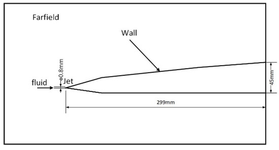
Figure 13.
Schematic diagram of lifting body structure.
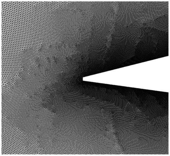
Figure 14.
Truncated cone mesh (part).
The boundary conditions of numerical simulation are the same as in Section 4.1. The total number of mesh elements is 1,024,653. The operation of local encryption is also carried out. The calculation results are shown in Figure 15 and Figure 16.
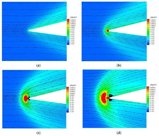
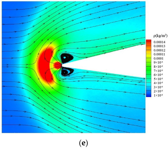
Figure 15.
Contour of density nephogram and streamline of truncated cone: (a) No opposing jet; (b) PR = 0.2; (c) PR = 0.4; (d) PR = 0.6; (e) PR = 0.8.
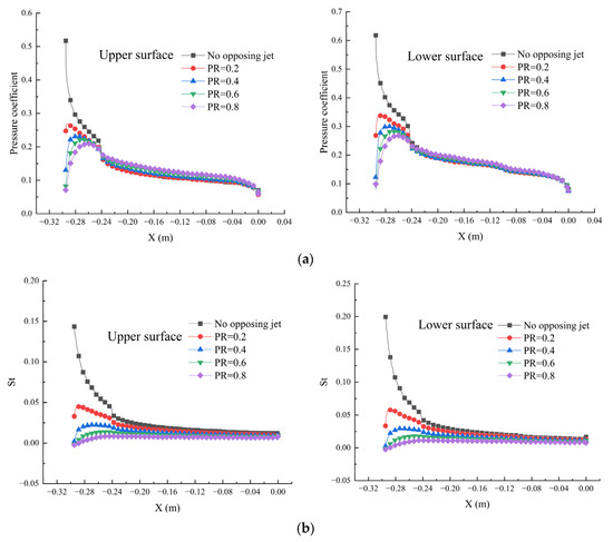
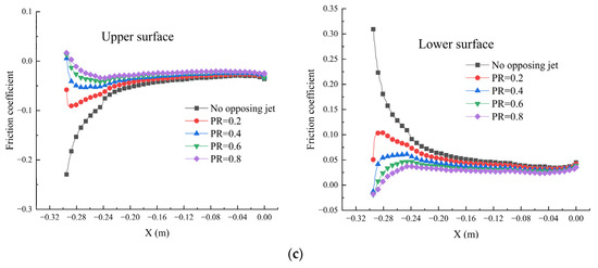
Figure 16.
Surface coefficient distribution of truncated cone: (a) Stanton number; (b) Pressure coefficient; (c) Friction coefficient.
Figure 15 shows the density distribution and streamline of the leading edge of the lifting body. When no opposing jet is applied, a conical shock wave occurs. After the opposing jet presents, the shock wave at the leading edge forms to become an arc. When PR = 0.2, due to the low jet pressure, the jet is greatly affected by the incoming inertial force, and the jet reflux is close to the wall, so there is no chance to form a vortex. The Mach disk is not fully formed because the jet pressure is too low. When PR = 0.4, the recirculation region begins to form. At this time, the eddy current intensity in the recirculation region is very low, and an apparent high-pressure expansion wave has been generated at the nozzle outlet. As the PR increases to 0.8, the recirculation region and Mach disk are gradually formed, resulting in a fierce vortex and a highly dense Mach disk. The shock wave is gradually pushed to the upstream by the Mach disk. The forming of the opposing jet structure of the truncated cone requires greater PR than that of the double ellipsoid because of the influence of the lifting body configuration. The leading-edge structure is too narrow. In practical terms, the jet nozzle is also very narrow, and the jet mass flow is low, so the jet with higher pressure is required to form a stable opposing jet structure.
Figure 16 shows the pressure coefficient, friction coefficient, and Stanton number on the wall. The opposing jet effect of the truncated cone is similar to that of Section 4.1. Generally, as PR increases to 0.8, each coefficient decreases to the lowest point, the Stanton number decreases by 101.4%, the pressure coefficient decreases by 87.54%, and the friction coefficient decreases by 99.4%. Only the wall near the nozzle shows the cooling and drag reduction effect, and the wall coefficient far away from the nozzle is almost the same as that without applying an opposing jet.
The opposing jet also has a limited effect on the resistance reduction and preventing heat for the truncated cone comparing with the coefficient of Section 4.1. Its effect is not significant comparing with the ball body. This is because the formed sharp shock wave is weak. The change of shock wave configuration by applying the opposing jet has a negative effect on cooling and drag reduction. The low speed and temperature of the jet reflux contribute the reduction of wall resistance and heat flux.
5. Conclusions
This paper aims at studying hypersonic vehicle resistance and aerodynamic heating in a rarefied flow field in near space by using opposing jet technology. The underlying physics of drag reduction and heat protection effect of opposing jets in hypersonic vehicles is explored in the near space rarefied flow. The conclusions are as follows:
- From the coefficient comparison, the opposing jet also has the function and effect of cooling and drag reduction in the rarefied flow field. The significant effect is observed near the nozzle region. Regarding the contribution of the applying jet, it is not that the higher the jet mass flow, the better the cooling and drag reduction effect is. It is necessary to adjust the optimal jet quantity by considering the cost and manufacturing process.
- Both the conical leading edge and the arc leading edge have the effect of cooling and drag reduction. By adding the flow field of the opposing jet, the values of various physical quantities decrease, the numerical curve becomes smooth, and the numerical change gradient decreases, which indicates that on the surface of the aircraft, temperature, heat exchange, friction, pressure, and other factors that will have a negative impact on the surface materials are weakened due to the effect of the opposing jet. Additionally, it reduces the fatigue loss of aircraft surface materials due to the excessive change gradient of wall physical quantities and the destructive loss caused by the excessive value of wall physical quantities, which has a positive significance for the protection of aircraft surfaces.
- Reduced coefficients occur within the coverage of the recirculation region. The eddy in the recirculation region due to the presence of the opposing jet consumes some energy and forms the low-pressure and low-temperature areas in the flow field. This eddy dissipation mainly affects cooling and drag reduction.
Author Contributions
Y.S., X.X. and J.Z. conceived the idea; Y.S. and X.X. designed the software; Y.S. read the relevant literature, completed the numerical experiment, analyzed the numerical experimental data; Y.S. and J.L. wrote the article; Z.Z. and Y.J. supervision; X.X. provide the funding. All authors have read and agreed to the published version of the manuscript.
Funding
This research was funded by the National Natural Science Foundation of China, Grant number 11902125.
Institutional Review Board Statement
Not applicable.
Informed Consent Statement
Not applicable.
Data Availability Statement
Not applicable.
Conflicts of Interest
The authors declare no conflict of interest.
References
- Laub, B.; Venkatapathy, E. Thermal protection system technology and facility needs for demanding future planetary missions[C]//planetary probe atmospheric entry and descent trajectory analysis and science. In Proceedings of the International Workshop Planetary Probe Atmospheric Entry and Descent Trajectory Analysis and Science, Lisbon, Portugal, 6–9 October 2003; Wilson, A., Ed.; ESA Publications Division: Noordwijk, The Netherlands, 2004; Volume 544, pp. 239–247. [Google Scholar]
- Wojcik, C.C.; Clark, L.T. Design, Analysis and Testing of Refractory Metal Heat Pipe Using Lithium as the Working Fluid. In Proceedings of the 26th AIAA Thermo Physics Conference, Honolulu, HI, USA, 24–26 June 1991; AIAA Press: Honolulu, HI, USA, 1991; pp. 1–4. [Google Scholar]
- Thornton, E.A. Thermal Structures: Four Decades of Progress. J. Aircr. 2002, 29, 485–498. [Google Scholar] [CrossRef]
- Lu, H.B.; Liu, W.Q. Research on thermal protection mechanism of forward-facing cavity and opposing jet combinatorial thermal protection system. Heat Mass Transf. 2014, 50, 449–456. [Google Scholar] [CrossRef]
- Lu, H.; Liu, W. Investigation of thermal protection system by forward-facing cavity and opposing jet combinatorial configuration. Chin. J. Aeronaut. 2013, 26, 287–293. [Google Scholar] [CrossRef]
- Ahmed, M.; Qin, N. Drag reduction using aerodisks for hypersonic hemispherical bodies. J. Spacecr. Rockets 2010, 47, 62–80. [Google Scholar] [CrossRef]
- Hayashi, K.; Aso, S. Effect of pressure ratio on aerodynamic heating reduction due to opposing jet. In Proceedings of the 36th AIAA Thermophysics Conference, Orlando, FL, USA, 23–26 June 2003. [Google Scholar]
- Bird, G.A. Recent advances and current challenges for DSMC. Comput. Math. Appl. 1998, 35, 1–14. [Google Scholar] [CrossRef]
- Wang, H.; Lai, B.; Qu, Z.; Ming, P. Moving impingement heat transfer in a three-dimensional rarefied hydrogen gas jet based on the direct simulation Monte Carlo method coupled with the finite difference method. Int. J. Heat Mass Transf. 2022, 188, 122586. [Google Scholar] [CrossRef]
- Mishra, S.K.; Prasad, K.D.; Nath, P.; Agarwal, D.; Kumar, S.S.; Bhardwaj, A. Effect of lunar landing on its surface, surrounding environment and hardware: A numerical perspective. Planet. Space Sci. 2022, 211, 105398. [Google Scholar] [CrossRef]
- Virgile, C.; Albert, A.; Julien, L. Optimisation of a hybrid NS–DSMC methodology for continuous–rarefied jet flows. Acta Astronaut. 2022, 195, 295–308. [Google Scholar] [CrossRef]
- Cao, Z.; Agir, M.; White, C.; Kontis, K. An open source code for two-phase rarefied flows: Rarefied Multiphase Foam. Comput. Phys. Commun. 2022, 276, 108339. [Google Scholar] [CrossRef]
- Cao, Z.; White, C.; Kontis, K. Numerical investigation of rarefied vortex loop formation due to shock wave diffraction with the use of rorticity. Phys. Fluids 2021, 33, 067112. [Google Scholar] [CrossRef]
- Agir, M.B.; White, C.; Kontis, K. Impact of Stagnation Temperature and Nozzle Configuration on Rarefied Jet Plume Interactions. J. Spacecr. Rocket. 2022, 1–17. [Google Scholar] [CrossRef]
- Wang, Z.; Zhang, X. Parametric research on drag reduction and thermal protection of blunt-body with opposing jets of forward convergent nozzle in supersonic flows. Acta Astronaut. 2022, 190, 218–230. [Google Scholar] [CrossRef]
- Ölçmen, S.; Cheng, G.C.; Branam, R.; Baker, J. Effects of counterflow jet on the performance of a generic rocket. Acta Astronaut. 2021, 182, 219–229. [Google Scholar] [CrossRef]
- Eghlima, Z.; Mansour, K. Drag reduction for the combination of spike and counterflow jet on blunt body at high Mach number flow. Acta Astronaut. 2017, 133, 103–110. [Google Scholar] [CrossRef]
- Sudarshan, B.; Rao, S.M.; Jagadeesh, G.; Saravanan, S. Effect of the axial cavity with an opposing high-pressure jet combination in a Mach 6 flow condition. Acta Astronaut. 2021, 178, 335–348. [Google Scholar] [CrossRef]
- Shen, B.X.; Liu, W.Q.; Yin, L. Drag and heat reduction efficiency research on opposing jet in supersonic flows. Aerosp. Sci. Technol. 2018, 77, 696–703. [Google Scholar] [CrossRef]
- Fan, W.J.; Li, S.B.; Zhou, J.; Huang, W.; Ou, M.; Zhang, R.R. Study on the drag and heat reduction performance of porous opposing jet in hypersonic flow. Int. J. Heat Mass Transf. 2019, 139, 351–361. [Google Scholar] [CrossRef]
- Zhang, W.; Wang, X.; Zhang, Z.; Han, F.; Zhao, S. Heat and drag reduction of single and combined opposing jets in hypersonic nonequilibrium flows. Aerosp. Sci. Technol. 2021, 121, 107194. [Google Scholar] [CrossRef]
- Finley, P.J. The flow of a jet from a body opposing a supersonic free stream. J. Fluid Mech. 1966, 26, 337–368. [Google Scholar] [CrossRef]
- Wilkes, J.; Glass, C.; Danehy, P.; Nowak, R. Fluorescence imaging of underexpanded jets and comparison with CFD. In Proceedings of the 44th AIAA Aerospace Sciences Meeting and Exhibit, Reno, NV, USA, 9–12 January 2006. [Google Scholar] [CrossRef][Green Version]
- Korzun, A.; Cordell, C., Jr.; Braun, R. Comparison of inviscid and viscous aerodynamic predictions of supersonic retropropulsion flowfields. In Proceedings of the 10th AIAA/ASME Joint Thermophysics and Heat Transfer Conference, Chicago, IL, USA, 28 June–1 July 2010; p. 5048. [Google Scholar]
- Venkatachari, B.S.; Ito, Y.; Cheng, G.; Chang, C.L. Numerical investigation of the interaction of counterflowing jets and supersonic capsule flows. In Proceedings of the 42nd AIAA Thermophysics Conference, Honolulu, HI, USA, 27–30 June 2011; p. 4030. [Google Scholar]
- Bird, G.A. The DSMC Method; CreateSpace Independent Publishing Platform: Scotts Valley, CA, USA, 2013. [Google Scholar]
- Moss, J.; Price, J.; Chun, C.H.H. Hypersonic rarefied flow about a compression corner-DSMC simulation and experiment. In Proceedings of the 26th Thermophysics Conference, Honolulu, HI, USA, 24–26 June 1991; p. 1313. [Google Scholar]
Publisher’s Note: MDPI stays neutral with regard to jurisdictional claims in published maps and institutional affiliations. |
© 2022 by the authors. Licensee MDPI, Basel, Switzerland. This article is an open access article distributed under the terms and conditions of the Creative Commons Attribution (CC BY) license (https://creativecommons.org/licenses/by/4.0/).