Article

Development of a Novel Dual Servo Magnetic Levitation Stage

1
Department of Mechanical System Design Engineering, Seoul National University of Science and Technology, Seoul 01811, Korea
2
Green Mobility R&D Center, Jeonbuk Institute of Automotive Convergence Technology, Gunsan 54158, Korea
3
Agency for Defense Development, Daejeon 34186, Korea
*
Author to whom correspondence should be addressed.
Actuators 2022, 11(6), 147; https://doi.org/10.3390/act11060147
Submission received: 28 April 2022 / Revised: 23 May 2022 / Accepted: 25 May 2022 / Published: 30 May 2022

Abstract

:
The main objective of this paper is to propose, design, and control a novel dual servo magnetic levitation stage which is precise and vacuum compatible. The dual servo mechanism, comprising a coarse stage and a fine stage, was applied to a magnetic levitation stage system for the first time. The dual servo stage achieves high precision and a long stroke at the same time. The fine stage, which comprises voice coil motors, achieves high-precision motion by overcoming the limit of the coarse stage, the form of which is a planar motor. The planar motor was mathematically modeled and analyzed with respect to the main design parameters, after which the fine stage was optimally designed to be driven by high force. Both stages including a common heat exchanger were manufactured, and the heat exchanger cools down the heat given off from the planar motor and voice coil motors. The position measuring system consisted of laser interferometers and capacitive sensors, and the integrated dual servo stage was controlled with a master–slave control scheme. The experimental results showed a precision of 10 nm, thus confirming the suitability of the developed magnetic levitation stage for a high-precision fabrication process such as wafer lithography.

1. Introduction

A stage is a system that makes a specimen track desired positions in real time. Numerous types of stage systems and their applications have been researched by many research groups [1,2,3,4,5,6,7], as described below. As stage systems—especially for semiconductor lithography—must be highly precise and have a long range of motion, there have been many studies on high-precision motion.
Although the rotary servo motor with a lead screw appeared to be an easy way to implement a stage system, it had a serious problem with backlash, resulting in poor precision [1]. A linear motor capable of transmitting actuation force directly to a moving object was used, but the friction from guides such as ball bearings, cross rollers, and dovetails was the main reason for the low precision [2]. A combination of linear motors with air bearings was used to eliminate the mechanical connection between the actuators and moving objects. By eliminating friction with non-contact configuration, high-precision motion was achieved [3,4].
In order to achieve a high degree of precision coupled with long-range motion, a dual servo mechanism was introduced. The dual servo stage is the combination of a coarse stage with a low degree precision but a long range of motion and a fine stage with a short range of motion range but a high degree of precision. Thanks to the air bearing and dual servo mechanism, the stage showed both high precision and a long range of motion [8]. A stage fitted with air bearings, however, cannot be used in next-generation semiconductor lithography processes. Some processes require a vacuum environment because irradiated light emanating from certain types of sources, such as the extreme ultraviolet (EUV) laser, is scattered through the air. As such, the stages used in the lithography process must be vacuum compatible. Magnetic levitation (Maglev) mechanisms that have vacuum compatibility, non-contact actuators, and non-contact guides have been introduced to stage systems [9,10,11]. Moreover, maglev stages equipped with a planar motor can achieve long-range, high-speed motion due to their relatively light moving body and rapid response [12,13,14,15,16,17,18,19]. Maglev planar motors generate actuation force between a two-dimensional magnet and coil arrays. They are categorized into two broad groups, i.e., the moving magnet type [19] and the moving coil type [20]. The former type does not have any wires attached to the mover, so there is no wire disturbance, but complex coil switching dependent on the mover position is necessary for control. Conversely, the moving coil type is disturbed by wire tension, but complex coil switching is not required.
For maglev planar motors, many academic trials have been carried out with the aim of improving its performance. One such trial involved the modification of the coil. More than two layers of coil were used [21,22,23] to increase the actuation force, and a new winding coil shape was tried [24]. Another approach consisted of enhancing the magnetic flux. Usually, the magnetic flux is increased with the use of the Halbach array and the variation in the magnet shape [14]. However, the maglev planar motor uses a highly complex scheme to control the current, which somewhat degrades the precision, despite the fact that many studies have attempted to develop an accurate current model [25,26,27].
This paper, however, proposes a novel maglev dual servo stage whose coarse stage is driven by a maglev planar motor and whose fine stage is driven by voice coil motors (VCMs). The fine stage realizes a very high degree of precision, while the coarse stage enables a long range of motion. In addition, the features of non-contact and vacuum compatibility contribute to the verification of the stage’s suitability for the wafer lithography process. The rest of the paper is organized as follows. Section 2 introduces the structure and the design results of the dual servo maglev stage; Section 3 presents the fabrication of the dual servo maglev stage and an explanation of the experimental setup; Section 4 presents the evaluation of the performance of the dual servo maglev stage by experiments; and, lastly, Section 5 presents the conclusion.

2. Structure of the Dual Servo Maglev Stage

The dual servo maglev stage is composed of a coarse stage and a fine stage, as shown in the schematic diagram of Figure 1. They are driven by two different types of electromagnetic actuators, namely, a planar motor and VCMs. An electromagnetic actuator employing Lorentz force has two parts, a stator and a mover. The dual servo maglev stage developed in this paper consists of three layers: the bottom is the coarse stage stator of the planar motor magnets; the middle is the coarse stage mover of the planar motor coils assembled with the fine stage stator of the VCM coils; and the top is the fine stage mover of the VCM magnets. The three layers are mechanically separated by a maglev mechanism which ensures that the stage has fast dynamics due to the absence of friction. Compared to the dual servo stage with an air bearing, in which the stages are separated without any mechanical contact, the dual servo stage equipped with a maglev mechanism allows the stage to be used in a vacuum environment.
For the VCMs of the fine stage, the magnets belong to the mover and the coils belong to the stator in order to be resistant to thermal deformation and easy to control without force coupling or wire disturbance. If the coils are placed on the moving body of the fine stage, the heat generated at the coils is directly transferred to the moving body and then to the specimen and the measurement system, making it a potential source of poor precision. In addition, parasitic force is induced when the moving body of the fine stage has yaw motion [7]. Finally, the wires connected to the external power supply are a source of disturbance for the moving body. Therefore, the moving magnet type was adopted for the structure of the fine stage.
For the planar motor of the coarse stage, the coils belong to the mover and the magnets belong to the stator, as this makes it easier to control and requires fewer current drivers than the moving magnet-stationary coil structure. Unlike the VCM, the planar motor generates a six-degrees-of-freedom (DOF) coupled force between the magnets and the coils, so the relationship between the current of each coil and the generated force is required to control the planar motor. We call that relationship “actuator kinematics”. The actuator kinematics relationship varies with respect to the position of the mover, since it depends on the magnetic field made by the permanent magnet array, and the magnetic field has spatial variation. When the coil array is the mover, the actuator kinematics relationship varies periodically in accordance with the repeated pattern of the stator and the magnet array. Thus, the actuator kinematics can be obtained by analytic or experimental calculation for one period of the magnet array. If the magnet array is the mover, the actuator kinematics relationship varies periodically in accordance with the repeated pattern of the coil array, which has a longer period than the magnet array. Furthermore, the finite size of the magnet array has the end-effect of showing a distorted magnetic field near the edge of the magnet array. Thus, the size of the real-time computation of the actuator kinematics is very large. In addition, a large number of current drivers are used, since the area of the stator is wider than that of the mover. Furthermore, because only the coils under the magnets can generate force, the coils should be turned on and off according to the position of the moving magnets. All of these factors increase the complexity of the control and power consumption. Considering the characteristics of the planar motor, the coarse stage was designed as a moving coil type.
According to the decision on the structure, all coils that are a source of the heat are placed on the middle layer. This arrangement separates the heat source from the moving part that carries the specimens. Additionally, it ensures that the top layer is not disturbed by wire tension related to the wires and coolant-carrying tubes.

2.1. Fine Stage

The fine stage requires at least six VCMs since it realizes six-DOF motion. In this paper, however, eight VCMs were used for symmetry. The fine stage mover is controlled so as to move on the XY plane by constraining the motion of the other three DOF. Therefore, it is useful to separate the role of the VCMs according to their use, which means decoupling each VCM force in accordance with the desired directions of motion. Two VCMs for motion along the x-axis and another two VCMs for motion along the y-axis were placed, as shown in Figure 2a. They are denoted by HVCM, which means the VCM for horizontal motion, i.e., the in-plane motion. Since the arrangement of the VCMs is symmetric, the forms of kinetics are the same for both directions of motion. In addition, the effort to regulate the yaw motion is even for all HVCMs. It is very beneficial when a practical control algorithm is applied, and it also simplifies the design process because one design result can be applied to all four HVCMs. VVCM means the VCM for vertical motion, i.e., the out-of-plane motion. The VVCMs could also be placed in the same manner as the HVCMs.
Each HVCM was designed to generate a force of at least 50 N, while each VVCM was designed to generate a force of at least 25 N to support and drive a fine stage mover with an expected weight of 10 kgf. The HVCMs and VVCMs have different sizes and structures. Each VCM was mathematically modeled, analyzed, and optimized to have high force. The design results were verified by FE (finite element) simulations and experiments measuring the force constant. The simple and compact structure of the VCMs exerted high force and uniform force that was constant throughout the entire range of motion. The detailed design process is presented in the previous work [27]. The final design of the fine stage is shown in Figure 2b,c and Table 1. The remainder of the space not occupied by the VCMs is used by sensors and mechanical motion stoppers. The final size of the designed fine stage is 250 mm in width and length and 52 mm in height. In the fine stage, the width and the length of the mover and the stator are the same, the height of the mover is 52 mm, and the height of the stator is 40 mm. If the mover is put on the stator like a lid, the overall height of the fine stage is 52 mm, which is the same as the height of the mover. After the fabrication of the dual servo stage, the mass of the mover of the fine stage was measured to be 8.89 kg, and the mass of the stator was measured to be 4.74 kg.

2.2. Coarse Stage

The coarse stage is levitated and driven by a maglev planar motor. The planar motor generates force between the two-dimensional magnet array and the three-phase coil array. The magnet array creates the spatially periodic magnetic field, and the coil array within the magnetic field generates force via the provided electric current. The main components of the force generated by one set of three-phase coils are parallel and perpendicular to the top surface of the magnet array. In order to regulate the two components of force, the magnitude and the phase of the electric current are controlled. Force generation using a multi-phase coil and a magnet array has been dealt with in detail in many previous studies [10,12,16,19,22,26]. In this section, the topology of the coil and the magnet array to realize the six-DOF motion of the coarse stage is presented. In addition, based on the electromagnetics and kinetics model, the design parameters are determined for the coarse stage so as to show optimal performance.

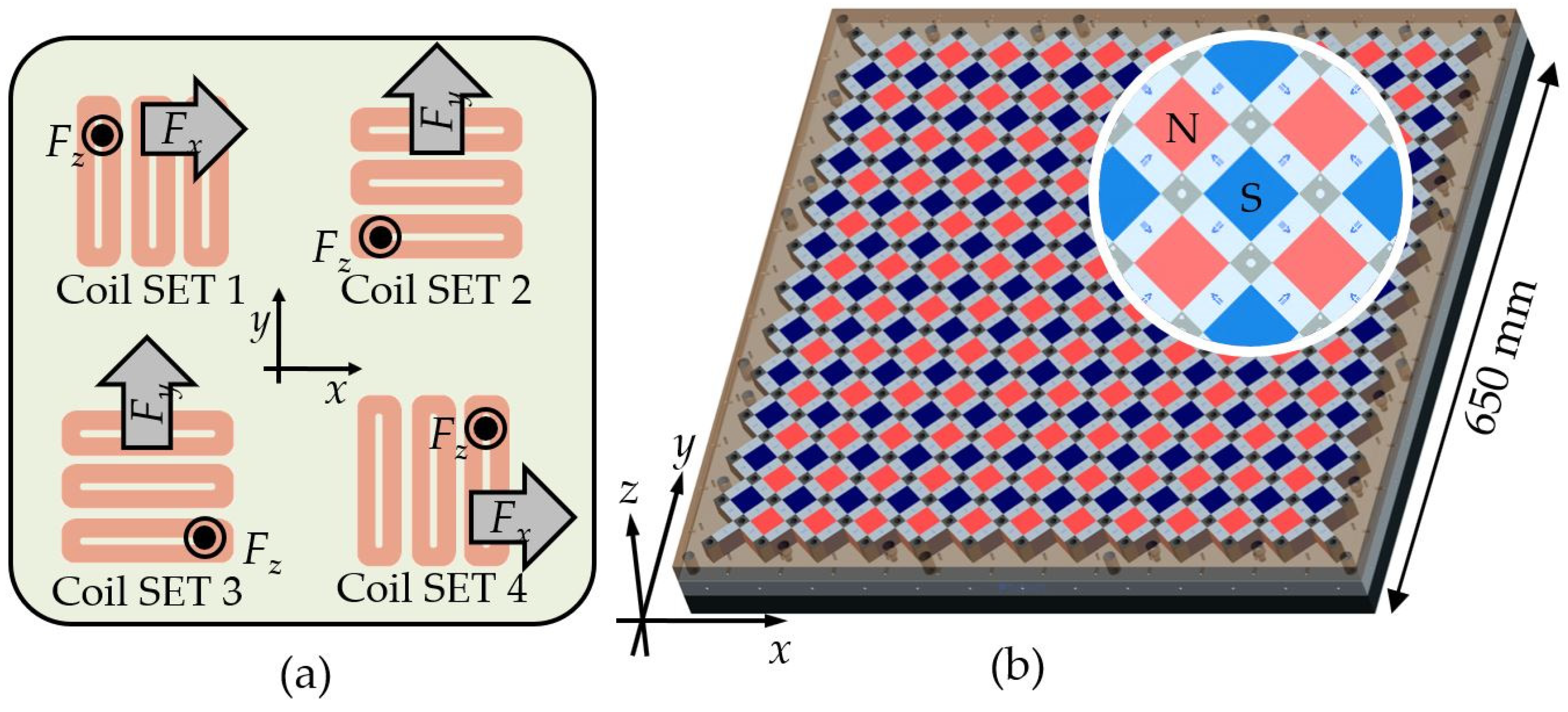
2.2.1. Coil and Magnet Array Topology

The coarse stage requires at least three sets of 3-phase coils to implement the six-DOF motions. In this research, however, four sets of 3-phase coils were used for structural symmetry, as in the case of the VCMs of the fine stage. As shown in Figure 3, two coil sets generate driving force along the x-axis and levitation force along the z-axis, whereas the other sets generate driving force along the y-axis and levitation force along the z-axis. For the benefit of the coil and magnet arrangement, the design result of one coil set can also be applied to the other coil set.
The magnet array generates a magnetic field in the space where the coils are placed. The spatial period of the magnetic field (i.e., the spatial distance between magnets) is dependent on the size of the coils. In order to obtain a higher Lorentz force, higher magnetic flux density is desirable. Since the magnet array is the stator of the coarse stage, there is no limitation on the weight. Thus, a steel back-yoke and a Halbach array of tall magnets were used.
The stator of the coarse stage is 650 mm in width and length and 65 mm in height. This enables a fine stage of 250 mm in width and length to have a stroke of about 200 mm. The mover of the coarse stage is the same as the stator of the fine stage, so it is 250 mm in width and length. The height is 52 mm, including the coolant heat exchanger. After the fabrication of the dual servo stage, the mover mass of the coarse stage was measured to be 5.3 kg. The total mass of the magnetically levitated mover, including about 0.1 kg of the coolant mass, is 19.03 kg.

2.2.2. Design Parameter Analysis

Figure 4 shows the design parameters of the magnets and coils. There are six independent parameters, five dependent parameters, and three pre-defined parameters, which are the dimensions of the magnets and coils. Descriptions of each parameter and the relationships between them are shown in Table 2, along with Equations (1)–(5).
g 3 = 3 2 4 τ
τ = l w c ( g 3 + 2 w c c + g 4 ) 4 2
τ m = α τ
l c c = 2 2 τ
g 1 = 2 2 3 τ 2 w c c g 2
Using design parameter analysis, the effect of the dependent design parameters on the important indices was inspected. The generated force, the mass of the mover, and the ohmic loss were observed when the height of the magnet, the ratio of the magnet length, the width of a coil bundle, the height of the coil, the current, and the diameter of the coil all varied from their nominal values. To calculate the indices, the number of coil turns and the electric resistance were obtained using Equations (6) and (7), respectively. ρe is the electric resistivity of the coil wire.
n = ( h c c 1.1 d c ) ( 2 3 ( w c c 1.1 d c 1 ) + 1 )
R = ρ e n ( 2 l c c + w c c + g 1 ) π d c 2 / 4
For the maglev planar motor, the thrust and levitation forces are the most important factors. Since the magnetic flux density has a harmonic form, the thrust and levitation forces of the equations can be approximated to first-order harmonic terms [9,15]. The amplitude of the force is represented by the product of the current and the force constant, kfx and kfz, as shown in Equations (8) and (9).
F c o i l , x = i c k f x c o s ( 2 π 2 τ x p )
F c o i l , z = i c k f z s i n ( 2 π 2 τ x p )
If we use three coil windings to create the constant force of a 3-phase coil set, the current can be provided as a harmonic function, while the resultant thrust and levitation forces are as shown in Equations (10) and (11). The magnitude of the generated force of a 3-phase coil can be defined as shown in Equation (12), where ic is the amplitude and ϕ is the phase of the provided current required to control the magnitude and the ratio of the thrust and levitation forces.
F x = k = 1 3 [ I c c o s ( 2 π 2 τ x p + 4 ( k 1 ) π 3 + φ ) k f x c o s ( 2 π 2 τ x p + 4 ( k 1 ) π 3 ) ] = 3 2 I c k f x ( c o s φ )
F z = k = 1 3 [ I c c o s ( 2 π 2 τ x p + 4 ( k 1 ) π 3 + φ ) k f z s i n ( 2 π 2 τ x p + 4 ( k 1 ) π 3 ) ] = 3 2 I c k f z ( s i n φ )
F c = ( F x 2 + F z 2 )
Then, the ohmic loss of (13) can be obtained from (7), (10), and (11). The mass is given by (14). M0 is the mass of the coarse stage mover, excluding the coils.
P c = 2 3 I c 2 R = 2 R 3 ( ( F x k f x ) 2 + ( F z k f z ) 2 )
M c = M 0 + 12 ρ c ( 2 w c c l c c h c c + 2 w c c ( w c c + g 1 ) h c c )
To compare the indices, the values were normalized by the nominal performance values obtained from the nominal values of the design parameters. Table 3 shows the nominal values and the variation in the design parameters. Figure 5 shows the tendency and sensitivity of the indices to the design parameters. Figure 5a shows that the force is saturated to a certain level when the height of the magnet array increases. The magnitude of the force with an hm of 20 mm is about 99.2% of the magnitude of the force with an hm of 45 mm. The magnetic flux density also shows similar behavior when the height of a magnet increases [15]. From Figure 5a, the design parameter hm was fixed to 20 mm for the later optimization process, because magnets that are larger than 20 mm barely increase the force and also make manufacturing and assembly difficult. Figure 5b shows that the Halbach magnet array is more advantageous than the normal magnet array corresponding to a ratio of 1. Figure 5b also shows that there is an optimal ratio which can be used to determine the size of the Halbach magnet array. Thus, the design variable α, which determines the sizes of the magnets, should be determined in the design process and handled well in the manufacturing process. From Figure 5c–f, it was found that there is a trade-off between heat generation and force generation. If the width and height of the coil winding are increased, the Lorentz force and electric resistance are also increased. An increase in force is desirable, but the accompanying increase in heat generation is unfavorable. The generated force and heat also increase simultaneously when the electric current increases. This phenomenon clearly shows that force is proportional to the current and that heat is proportional to the square of the current. Figure 5f shows that heat generation is very sensitive to variations in the coil diameter below the value of about 0.8 mm. Figure 5c,d show that mass is relatively insensitive to the design parameters, since the portion of the coil is small compared to the main body of the coarse stage mover. The mass is changed by less than 5% or so when the design parameters related to the coil winding vary. However, the other performance indices show a trade-off, and the optimal performance and the optimal design parameters should be determined through an optimization process. The graphs in Figure 5c,d,f are not smooth because the number of coil turns does not vary continuously with respect to the coil’s width, height, and diameter. Thus, the design parameters wc, hc, and d are handled in a discretized manner through the optimization process.

2.2.3. Optimization

The objective of the optimization is set to maximize the force and minimize the mass of the coarse stage mover. The production of high force is advantageous not only for acceleration and deceleration within a limited range of motion but also for a fast dynamic response. The mover of the coarse stage is always levitated during the operation, which causes constant power consumption. However, the amount of power consumption can be decreased if the mover is light. Furthermore, the lighter the mover, the easier it is for the stages to achieve the specified acceleration with a smaller inertial force. The objective and the constraints are presented in Table 4.
Since the planar motor must support the weight of the mover of the coarse stage and the whole fine stage, each 3-phase coil set should be able to generate at least 50 N in the vertical direction for the expected weight of 20 kgf. At the same time, the planar motor must accelerate the mover in the horizontal direction. Therefore, one set of coils should be able to generate at least 100 N, because two sets of coils should exert at least 200 N in the horizontal direction. The details of the values are described in a previous work [27]. In addition, a larger ohmic loss means that more electric energy is converted to heat, which is then transferred to the surrounding components, causing a negative effect. The value of the ohmic loss is constrained to 130 W by the simulation that is explained in the next section.
The optimization was conducted using the SQP (Sequential Quadratic Programming) algorithm of MATLAB. Since the coil diameter is available only in a discrete size in practice, optimized solutions were obtained for each coil diameter. As shown in Table 5, the results show similar levels of force, ohmic loss, and mass for the different coil diameters. There is no feasible solution for coil diameters that are more than 0.9 mm or less than 0.5 mm in diameter. Among the optimization results in Table 5, a coil with a diameter of 0.6 mm was chosen for the optimized value due to the limited features of the current amplifier. The maximum current output and the terminal voltage of the current amplifier were 8 A and 48 V, respectively. In cases in which a coil diameter is more than 0.6 mm, a current exceeding 8 A should be used, while a terminal voltage of 56.5 V is needed when a coil diameter is 0.5 mm; for a coil diameter of 0.6 mm, however, the terminal voltage should be 39.5 V.

3. Realization of the Dual Servo Maglev Stage

3.1. Heat Exchanger

The generation of heat by the coils of the fine stage and the coarse stage can be a very serious problem. An increase in temperature due to heat can cause the self-bonded coil wires to become unglued, the magnets to lose their magnetism above the Curie temperature, and the thermal deformation of the stage structure, leading to the propagation of motion errors to a specimen or sensors. Therefore, most of the heat generated by the coils should be transferred to a heat sink, for which purpose a heat exchanger was used.
A heat exchanger with a coolant situated right behind the coils was designed. Water was used as the coolant, and two water channels were engraved on the bottom surface of the fine stage stator. The material of the stator is aluminum with very high thermal conductivity. The water channels are closed by a ceramic block on which the coil array for the planar motor is placed. A ceramic coil bearer was chosen due to its high thermal conductivity for heat transfer and to the fact that it does not cause eddy currents induced by the magnet array. The coolant circulates through each channel, and the heat from the coils is transferred to the coolant. The pressure and temperature of the water at the channel inlet are maintained by a chilling circulator (RW-2040G, JEIO Tech., Daejeon, Korea).
The heat transfer from the coils of both the fine and coarse stages to the water coolant was verified by FE simulation (Ansys Icepak, Canonsburg, PA, US). In the analysis model, the coil windings were set to the source of constant heat generation. Heat generation of 150 W was applied to each coil set of the planar motor, while 17.5 W was applied to each coil of the VCM. A combined total of 740 W of heat was assumed to be generated by all the coils. The cross section of the channel was a square, with an area of 5 × 5 mm2, and the water flow rate from the chilling circulator was 0.5 L/min. The results of the simulation show that the total heat generation of 740 W is well dissipated to the water flowing through the channel. The simulation results in Figure 6 show that the coils, ceramic block, and stator of the fine stage and the coolant have a temperature of less than 50 °C. The difference in temperature within the structure is less than 10 °C. In consideration of the fact that the temperature endurance limit is 100 °C for the coil windings and 90 °C for the magnets, it is concluded that there is no thermal problem, based on the results of the simulation. Based on these results, the constraint of optimization was set to 130 W instead of 150 W, taking into account a margin of roughly 10%.

3.2. Experiment Setup

3.2.1. Sensors

Two sets of six sensors were employed to realize the six-DOF motions of the dual servo maglev stage. The motion of the fine stage was measured globally using three laser interferometers and three capacitive sensors installed outside the motion system. The laser interferometers (RLE10, Renishaw, Gloucestershire, UK), which are denoted by SG1~SG3, were used to measure the in-plane motion of the fine stage by targeting the bar mirrors placed on the sides of the fine stage. The capacitive sensors (C5S, Lion precision, Oakdale, MN, USA), which are denoted by SG4~SG6, were used to measure the out-of-plane motion of the fine stage by targeting the top surface of the fine stage. The motion of the coarse stage relative to that of the fine stage was measured locally using the six capacitive sensors installed between the stages. The capacitive sensors (C9.5R and C8S, Lion Precision, Oakdale, MN, USA), denoted by SL1~SL6, measured the motion of the coarse stage relative to that of the fine stage. The arrangement of the sensors is shown in Figure 7, and the specifications of the sensors are shown in Table 6.

3.2.2. Electric Devices and Data Acquisition

All the coils of the VCMs and the planar motor are driven by linear current amplifiers (TA115, Trust automation, San Luis Obispo, CA, USA), and all the amplifiers are powered by a customized power supply (OPM505, ODA Technologies, Incheon, Korea). A controller (DS1005, dSPACE, Paderborn, Germany) for the high-level control algorithm was used for feedback control. The dual servo maglev system is shown in Figure 8.

3.2.3. Control Strategy

The control strategy for the dual servo stage is the master–slave control algorithm. The fine stage, whose position is measured by the global sensors, is the master, while the coarse stage, whose position relative to the fine stage is measured by the local sensors, is the slave. The control block diagram is shown in Figure 9. The master is controlled to follow the main command rf, and the slave is controlled to follow the master. The command of the slave, rc, is always the zero vector, since the feedback is the relative motion between the fine stage and the coarse stage.
By utilizing the pseudo inverse of the actuator kinematics of the fine stage, K f + , the coupled plant model can be converted to a simple decoupled plant model of six-DOF in accordance with the Cartesian coordinates. Thus, six simple PID controllers were used based on the six-SISO (Single Input Single Output) model. The position vectors x a f and x m f denoted in Figure 9 represent the actual and measured positions of the mass center of the fine stage. The measured position, x m f , is obtained from the sensor signals, S f , by the sensor transformation matrix, H f , which is determined by the position of the sensors. The coarse stage is controlled in the same manner as the fine stage. However, in this case, the actuator kinematics relationship is dependent on the position of the coarse stage. Thus, the pseudo inverse of the actuator kinematics K c + ( x c ) is determined at every position in real time. By utilizing the pseudo inverse, the PID controller has six output signals of control force as well as six feedback signals of displacement in the Cartesian coordinates. The position vector x a c represents the actual position of the mass center of the coarse stage in the global sense, and x m c represents the measured position of the mass center of the coarse stage relative to that of the fine stage. The sensor transformation matrix H c is obtained from the sensor signals and the measured positions, S c and x m c , respectively.

4. Results

The dual servo maglev stage was controlled using the master–slave control scheme, and the basic positioning performances were evaluated accordingly.
The motion stroke of the maglev dual servo stage was evaluated. As a result of the position-controllable range, the x-axis is 100 mm and the y-axis is 140 mm, as shown in Figure 10. Since the size of the coarse stage mover is 250 mm and the size of the magnet array of the coarse stage stator is 600 mm, the motion range based on simple geometry was expected to be 350 mm at the design stage. However, the length of the mirror located above the fine stage mover targeted by the laser interferometers used as a feedback sensor is 260 mm. Considering the distance between the double path beams, the position-controllable range is about 200 mm. Additionally, as the mover approaches the outer edge of the permanent magnet array, the periodicity of the magnetic flux density decreases due to the edge effect of the permanent magnets, and the accuracy of the kinematics model obtained using the harmonic model for control decreases. For this reason, the x-axis and y-axis motion strokes were lower than the design value, and two laser interferometers were installed along the x-axis to measure the yaw motion, which further reduced the motion stroke in the x-axis.
The in-position stability of the dual servo stage in each axis was evaluated, and the corresponding root-mean-square (RMS) values are shown in Figure 11 and Table 7. The coarse stage was levitated 1 mm from the surface of the magnet array, and the fine stage was levitated 0.5 mm from the coarse stage. The stages were controlled to be in position, and the feedback sensor data were measured for 20 s. As shown in Figure 11, the positioning stability of the fine stage is greatly superior to that of the coarse stage. The in-plane position of the fine stage was kept to within 10 nm in the translational directions and to around 0.01 arcsec in the rotational direction, while the in-plane position stability of the coarse stage was larger than 100 nm in the translational directions and larger than 0.2 arcsec in the rotational directions. The positioning stability in the y direction is superior to that of the x direction because the sensor signals from the two laser interferometers are averaged. During the experiment, the temperature was measured with a non-contact infrared thermometer while the stage levitated in place was being cooled by 10 °C water. The temperature did not exceed 30 °C. In the FE analysis, the maximum power consumption was assumed in all coils, but in practice, the temperature was observed to be much lower by using less power.
In order to evaluate the minimum positioning resolution, stepped trajectories were commanded. Figure 12 shows the evaluated result. In the translational direction, 40 nm, 30 nm, and 100 nm steps were clearly resolved in the x, y, and z directions, respectively. In the rotational direction, 0.15 arcsec, 0.15 arcsec, and 0.04 arcsec steps were clearly resolved in the θx, θy, and θz directions, respectively.
Figure 13 shows the settling performance of the dual servo maglev stage. The magnitude of the step command was 1 mm, and the time taken for the stage to settle to within 1% of the command was measured. The fine stage settled within 200 ms for both the x and y directions, while the coarse stage showed a settling time of 470 ms.
The current provided to the coarse and fine stages was measured while moving the stage by 50 mm in the x and y directions. The distance of 50 mm corresponds to the length of one spatial period of both the magnet array and the magnetic field. As shown in Figure 14, while the dual servo maglev stage moves in the x direction, the current provided to the six coils of the planar motor placed along the y-axis varies considerably, generating a levitation force according to the spatially varying magnetic field. The variation in the current provided to the other six coils placed along the x-axis is small because the variation in the magnetic field affecting the coils is small when the stage is moving in the x direction. The same phenomenon is observed when the stage moves in the y direction. The current provided to the VVCMs is steady because the vertical level of the fine stage is maintained while the stage moves in the x and y directions; however, the current provided to the HVCMs varies, generating force in the x or y directions and moving the fine stage.

5. Conclusions

This paper proposes a novel dual servo magnetic levitation stage designed to achieve a high degree of precision in the next-generation semiconductor lithography process. It is also vacuum compatible and allows the range of motion to be expanded easily due to the planar motor scheme. The structure of the novel dual servo magnetic levitation stage is composed of three layers: the bottom is the coarse stage stator of the planar motor magnets; the middle is the coarse stage mover of the planar motor coils assembled with the fine stage stator of the VCM coils; and the top is the fine stage mover of the VCM magnets. The layers are separated by the maglev mechanism, which removes mechanical connection and friction between the layers. Therefore, the stage offers a fast dynamics response and a high degree of precision.
As the middle layer has all the coils of the coarse and fine stages, the coarse stage becomes a moving coil type and the fine stage becomes a moving magnet type. The coarse stage belongs to the moving coil type in the form of a planar motor, which makes it easy to control due to the simple actuator kinematics, and it is free of the end-effect of the magnet array. With this type, the coarse stage requires fewer current drivers and has an easier control scheme without complex coil switching. The fine stage of the moving magnet type is free from direct heat transfer and is easy to control without force coupling and wire disturbance. Moreover, the placement of the coils allows only the middle layer to cool, and the coolant-carrying tubes do not disturb the top layer.
Both stages were analytically modeled with respect to the design parameters. Electromagnetics, kinetics, and electrics were used to create a mathematical model. The effect of the design parameters on the performance of the stage has been inspected. Based on the model and the study, the optimization process determines the design parameters and the final performances of the stage. The fine stage and the coarse stage are integrated into the dual servo maglev stage, and they are equipped with sensors for position feedback. The master–slave concept was used for the control strategy regarding the coordinate of the fine stage as the master and the relative coordinate between the fine stage and the coarse stage as the slave. Linear current amplifiers are utilized to input current to the coils of the planar motor and the voice coil motors. The real-time controller, with several data acquisition boards and a processor, is used to realize the 12-SISO PID control algorithms.
The results of the performance evaluation show that the dual servo stage has an in-position stability of 10 nm along the motion directions of the x-axis and the y-axis. Additionally, the experiment on a 1% settling time for a 1 mm step command shows that the fine stage settles within 200 ms for both the x and y directions, while the coarse stage exhibits a settling time of 470 ms. Therefore, it is concluded that the novel dual servo magnetic levitation stage designed and manufactured for this paper delivers a high degree of precision and fast dynamics.

Author Contributions

Conceptualization and methodology, D.A.; software, J.J.; simulation and optimization, J.-W.J.; formal analysis and experiments, J.-W.J., H.Y. and J.J.; data curation and writing—original draft preparation, D.A.; writing—review and editing, H.Y. and J.J. All authors have read and agreed to the published version of the manuscript.

Funding

This work was supported by a Korea Institute for Advancement of Technology (KIAT) grant funded by the Korean Government (MOTIE) (P0012744, The Competency Development Program for Industry Specialist).

Institutional Review Board Statement

Not applicable.

Informed Consent Statement

Not applicable.

Data Availability Statement

Not applicable.

Conflicts of Interest

The authors declare no conflict of interest.

References

  1. Otsuka, J. Nanometer level positioning using three kinds of lead screws. Nanotechnology 1992, 3, 29–36. [Google Scholar] [CrossRef]
  2. Futami, S.; Furutani, A.; Yoshida, S. Nanometer positioning and its micro-dynamics. Nanotechnology 1990, 1, 31–37. [Google Scholar] [CrossRef]
  3. Ro, S.-K.; Park, J.-K. Development of a Miniature Air-bearing Stage with a Moving-magnet Linear Motor. Int. J. Precis. Eng. Manuf. 2008, 9, 19–24. [Google Scholar]
  4. Ro, S.-K.; Kim, S.; Kwak, Y.; Park, C.H. A linear air bearing stage with active magnetic preloads for ultraprecise straight motion. Precis. Eng. 2010, 34, 186–194. [Google Scholar] [CrossRef]
  5. Wang, H.; Zhang, X. Input coupling analysis and optimal design of a 3-DOF compliant micro-positioning stage. Mech. Mach. Theory 2008, 32, 400–410. [Google Scholar] [CrossRef]
  6. Kim, H.Y.; Ahn, D.H.; Gweon, D.G. Development of a novel 3-degrees of freedom flexure based positioning system. Rev. Sci. Instrum. 2012, 83, 055114. [Google Scholar] [CrossRef]
  7. Kim, K.H.; Gweon, D.G.; Jung, H.S.; Lee, S.H.; Hong, M.S.; Lee, M.-G. A Stage Based on Voice Coil Motor with High Speed and Long Range for Laser Micro/Nano Fabrication. Key Eng. Mat. 2007, 345, 757–760. [Google Scholar] [CrossRef]
  8. Kim, K.H.; Choi, Y.M.; Nam, B.-U.; Lee, M.-G. Dual servo stage without mechanical coupling for process of manufacture and inspection of flat panel displays via modular design approach. Int. J. Precis. Eng. Manuf. 2012, 13, 407–412. [Google Scholar] [CrossRef]
  9. Compter, J.C. Electro-dynamic planar motor. Precis. Eng. 2004, 28, 171–180. [Google Scholar] [CrossRef] [Green Version]
  10. Peijnenburg, A.T.A.; Vermeulen, J.P.M.; van Eijk, J. Magnetic levitation systems compared to conventional bearing systems. Microelectron. Eng. 2006, 83, 1372–1375. [Google Scholar] [CrossRef]
  11. Jansen, J.W.; van Lierop, C.M.M.; Lomonova, E.A.; Vandenput, A.J.A. Ironless magnetically levitated planar actuator. J. Appl. Phys. 2008, 103, 07E905. [Google Scholar] [CrossRef] [Green Version]
  12. Boeij, J.D.; Lomonova, E. Experimental verification of look-up table based real-time commutation of 6-DOF planar actuators. J. Syst. Des. Dyn. 2009, 3, 563–571. [Google Scholar] [CrossRef] [Green Version]
  13. Ueda, Y.; Ohsaki, H. Six-Degree-of-Freedom Motion Analysis of a Planar Actuator with a Magnetically Levitated Mover by Six-Phase Current Controls. IEEE Trans. Magn. 2008, 44, 4301–4304. [Google Scholar] [CrossRef]
  14. Kim, J.J.; Lee, M.G.; Jeong, J.; Gweon, D.G. Design of a magnetically levitated six degrees-of-freedom planar motor using T-shape halbach magnet array. In Proceedings of the Euspen International Conference, Delft, The Netherland, 31 May 2010. [Google Scholar]
  15. Jansen, J.W. Magnetically Levitated Planar Actuator with Moving Magnets: Electromechanical Analysis and Design. Ph.D. Thesis, Technical University Eindhoven, Eindhoven, The Netherlands, 2007. [Google Scholar]
  16. Zhu, H.; Pang, C.K.; Law, T.L.; Teo, T.J. Design and Control of a Six Degrees-of-Freedom Magnetically Levitated Positioning System. IFAC Pap. 2016, 49, 127. [Google Scholar] [CrossRef]
  17. Zhu, H.; Teo, T.J.; Pang, C. K, Conceptual design and modeling of a six degrees-of-freedom unlimited stroke magnetically levitated positioner. In Proceedings of the IEEE/ASME International Conference on Advanced Intelligent Mechatronics, Besacon, France, 8–11 July 2014. [Google Scholar] [CrossRef]
  18. Zhang, L.; Kou, B.; Zhang, H.; Guo, S. Characteristic Analysis of a Long-Stroke Synchronous Permanent Magnet Planar Motor. IEEE Trans. Magn. 2012, 48, 4658–4661. [Google Scholar] [CrossRef]
  19. Lu, X.; Usman, I.U.R. 6D direct-drive technology for planar motion stages. CIRP Ann. 2012, 61, 359–362. [Google Scholar] [CrossRef]
  20. Rovers, J.M.M.; Janse, J.W.; Lomonova, E.A. Design and measurements of the Double Layer Planar Motor. In Proceedings of the International Electric Machines & Drives Conference, Chicago, IL, USA, 12–15 May 2013. [Google Scholar] [CrossRef]
  21. Guo, L.; Zhang, H.; Galea, M.; Li, J.; Lu, W.; Gerada, C. Analysis and Design of a Magnetically Levitated Planar Motor with Novel Multilayer Windings. IEEE Trans. Magn. 2015, 51, 8106909. [Google Scholar] [CrossRef] [Green Version]
  22. Kou, B.; Xing, F.; Zhang, C.; Zhang, L.; Zhou, Y.; Wang, T. Improved ADRC for a Maglev Planar Motor with a Concentric Winding Structure. Appl. Sci. 2016, 6, 419. [Google Scholar] [CrossRef] [Green Version]
  23. Zhang, L.; Kou, B.; Xing, F.; Zhang, H. Analysis and comparison of two two-dimensional Halbach permanent magnet arrays for magnetically levitated planar motor. J. Appl. Phys. 2014, 115, 17E704. [Google Scholar] [CrossRef]
  24. Zhang, L.; Kou, B.; Li, L.; Zhao, B. Modeling and design of an integrated winding synchronous permanent magnet planar motor. In Proceedings of the 16th International Symposium on Electromagnetic Launch Technology, Beijing, China, 15–19 May 2012. [Google Scholar] [CrossRef]
  25. Usman, I.U.R.; Lu, X. Force Ripple Attenuation of 6-DOF Direct Drive Permanent Magnet Planar Levitating Synchronous Motors. IEEE Trans. Magn. 2015, 51, 8208708. [Google Scholar] [CrossRef]
  26. Xing, F.; Kou, B.; Zhang, L.; Yin, X.; Zhou, Y. Design of a Control System for a Maglev Planar Motor Based on Two-Dimension Linear Interpolation. Energies 2017, 10, 1132. [Google Scholar] [CrossRef] [Green Version]
  27. Ahn, D.; Kim, H.; Choi, K.; Choi, Y.-M.; Lim, J.-Y. Design process of square column-shaped voice coil motor design for magnetic levitation stage. Int. J. Appl. Electrom. 2020, 62, 517–540. [Google Scholar] [CrossRef]
Figure 1. Schematic diagram showing the structure of the dual servo maglev stage.
Actuators 11 00147 g001
Figure 2. Design of the fine stage: (a) The topology of the VCMs; (b) the fine stage stator with coils; and (c) the fine stage mover with magnets (inverted) [27]. Reprinted from International Journal of Applied Electromagnetics and Mechanics, 62, Dahoon Ahn, et al., Design process of square column-shaped voice coil motor design for magnetic levitation stage, 517–540, Copyright (2020), with permission from IOS Press.
Actuators 11 00147 g002
Figure 3. Design of the coarse stage: (a) The topology of the 3-phase coils; (b) the coarse stage stator with a two-dimensional magnet array.
Actuators 11 00147 g003
Figure 4. Design parameters of the planar motor, (a) magnet array, (b) coil array, and (c) four sets of 3-phase coils.
Actuators 11 00147 g004
Figure 5. Results of the sensitivity analysis. (a) effect of height of the magnet array; (b) effect of the Halbach magnet ratio; (c) effect of bundle width of the coil; (d) effect of height of the coil array; (e) effect of electric current of the coil; (f) effect of height of the coil array.
Actuators 11 00147 g005
Figure 6. FE analysis results of the water-cooling heat exchanger: (a) configuration of the heat exchanger; (b) coolant channel engraved on the stator of the fine stage (c) temperature at the coils; (d) temperature at the aluminum block (the stator of the fine stage); (e) temperature at the ceramic block (the stator of the coarse stage) (f) temperature at the coolant.
Actuators 11 00147 g006
Figure 7. Arrangement of the motion feedback sensors: (a) global sensors for the fine stage, (b) local sensors for the coarse stage.
Actuators 11 00147 g007
Figure 8. The realized dual servo maglev stage system.
Actuators 11 00147 g008
Figure 9. Control block diagram of the master–slave control scheme of the dual servo maglev stage.
Actuators 11 00147 g009
Figure 10. The evaluated motion stroke data of the dual servo stage: (a) x direction, (b) y direction.
Actuators 11 00147 g010
Figure 11. The evaluated in-position stability data of the dual servo stage: (a) x direction, (b) y direction, (c) z direction, (d) θx direction, (e) θy direction, (f) θz direction.
Actuators 11 00147 g011
Figure 12. The evaluated minimum positioning resolution data of the dual servo stage: (a) x direction, (b) y direction, (c) z direction, (d) θx direction, (e) θy direction, (f) θz direction.
Actuators 11 00147 g012
Figure 13. The evaluated settling time data of the dual servo stage: (a) x direction, (b) y direction.
Actuators 11 00147 g013
Figure 14. The current provided to the coils when the dual servo maglev stage moves 50 mm along the x-axis and y-axis: (a) measured position along x direction, (b) measured position along y direction, (c) electric current applied to the coils placed along the y-axis, (d) electric current applied to the coils placed along the x-axis, (e) electric current applied to the HVCMs, (f) electric current applied to the VVCMs.
Actuators 11 00147 g014
Table 1. Design specifications of the VCMs of the fine stage [27]. Reprinted from International Journal of Applied Electromagnetics and Mechanics, 62, Dahoon Ahn, et al., Design process of square column-shaped voice coil motor design for magnetic levitation stage, 517–540, Copyright (2020), with permission from IOS Press.
Design ResultsHVCMVVCM
Size95 × 50 × 40 mm355 × 55 × 40 mm3
Wire diameter0.6 mm0.4 mm
Number of turns297 turns738 turns
Electric resistance3.29 Ω11.29 Ω
Max. voltage26.5 V36.9 V
Max. current3.43 A1.24 A
Max. power17.5 W17.5 W
Max. Force52.4 N28.2 N
Force constant15.6 N/A22.3 N/A
Table 2. Design parameters of the planar motor.
Design ParametersDescription
Independent parameters h m c Height of the magnet array
α Ratio of the length of the main magnet to the half-pitch of the magnet array
w c c Width of a bundle of coil threads with the same current direction
h c c Height of the coil array
i c Current through the coil
d c Diameter of the core of the coil (without sheath)
Dependent parameters τ Half-pitch of the magnet array
τ m Length of the main magnet
l c c Effective length of the coil
g 1 Center gap of the coil winding
g 3 Distance between the coil sets which generate forces in the same direction
Pre-defined parameters g 2 Pre-defined to match the phase of the current and the magnetic flux density: 0 mm
g 4 Pre-defined to consider manufacturing the tolerance of coil winding: 8 mm
l w c Pre-defined by the size of the mover of the coarse stage: 250 mm
MaterialsMagnetNdFeB, N-38H, magnetization of 8.99 × 10⁵ A/m
CoilCopper wire, resistivity of 1.793 × 10⁻⁸ Ωm
YokeAISI 1020
Table 3. Variations in the design parameters of the planar motor for sensitivity analysis.
Independent Design ParametersNominal ValueVariation
h m 25 mm5 mm–45 mm
α 0.60.2–1
w c c 8 mm5 mm–11 mm
h c c 5 mm2 mm–8 mm
i c 2 A1 A–3 A
d c 0.8 mm0.3 mm–1.3 mm
Table 4. Objective and constraints of optimization for the 3-phase coil set of the planar motor.
Objective min [ ( M c / F c ) 2 ]
ConstraintsVertical force>50 N
Horizontal force >100 N
Ohmic loss<130 W
Table 5. Results of optimization with respect to the various coil diameters.
Design ParametersConstraints
α w c c (mm) h c c (mm) i c (A) d c (mm) F c   ( N ) P c   ( W ) m c   ( kg )
0.66813.95.985.170.5154.913019.17
0.67113.96.067.440.6155.813019.20
0.67213.96.639.680.7154.213019.23
0.64613.95.8313.620.8151.313019.11
0.67113.98.0814.540.9160.013019.97
Table 6. Specifications of the sensors.
SensorsMeasurement RangeTheoretical Resolution
(16-bit A/D)
Laser interferometersRLE101 m38.63 pm
Capacitive sensorsC5S10 μm150 pm
C9.5R1250 μm19.07 nm
C8S2000 μm30.52 nm
Table 7. The evaluated in-position stability of the dual servo stage with RMS values.
(RMS Value)x (nm)y (nm)z (nm)θx (arcsec)θy (arcsec)θz (arcsec)
Fine stage9.297.8523.20.03230.04000.0106
Coarse stage115.94275.87170.730.36400.26620.2435
Fine-to-coarse ratio (%)8.012.8513.598.8715.034.35
Publisher’s Note: MDPI stays neutral with regard to jurisdictional claims in published maps and institutional affiliations.

