
Development of Durability Test Device for Magnetorheological Fluids with Two Types of Rotors and Their Long-Term Torque Characteristics


Abstract
:1. Introduction
2. Design of Durability Test Device
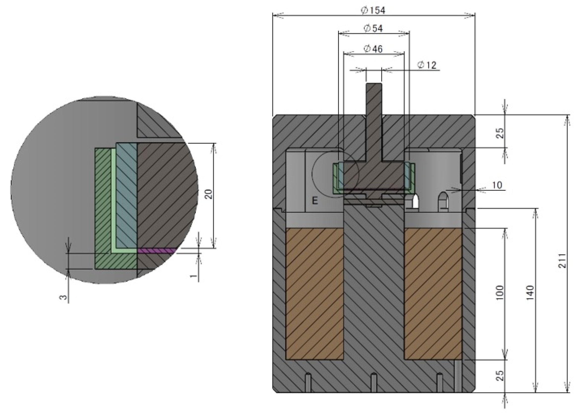
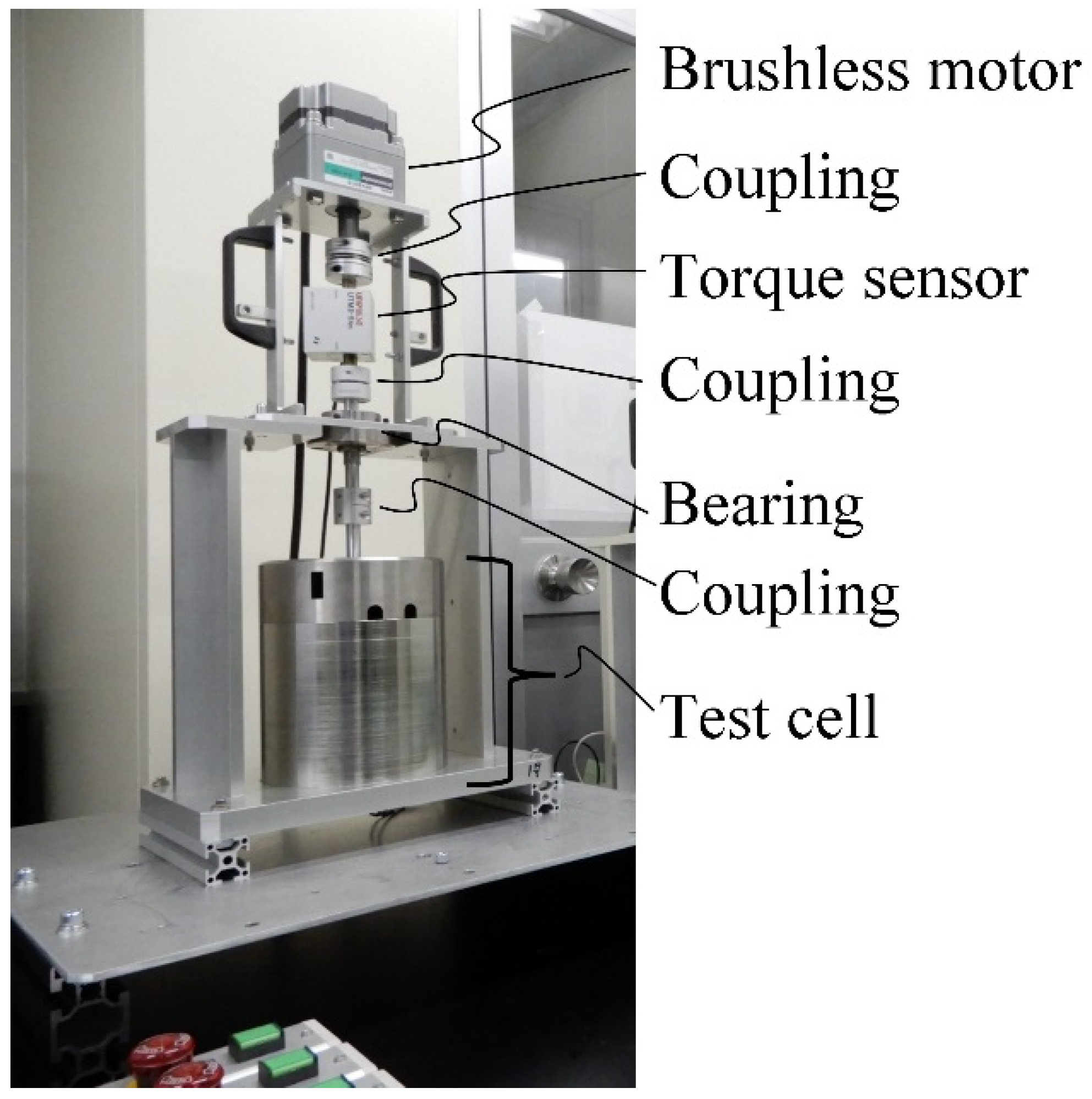
2.1. Basic Structure
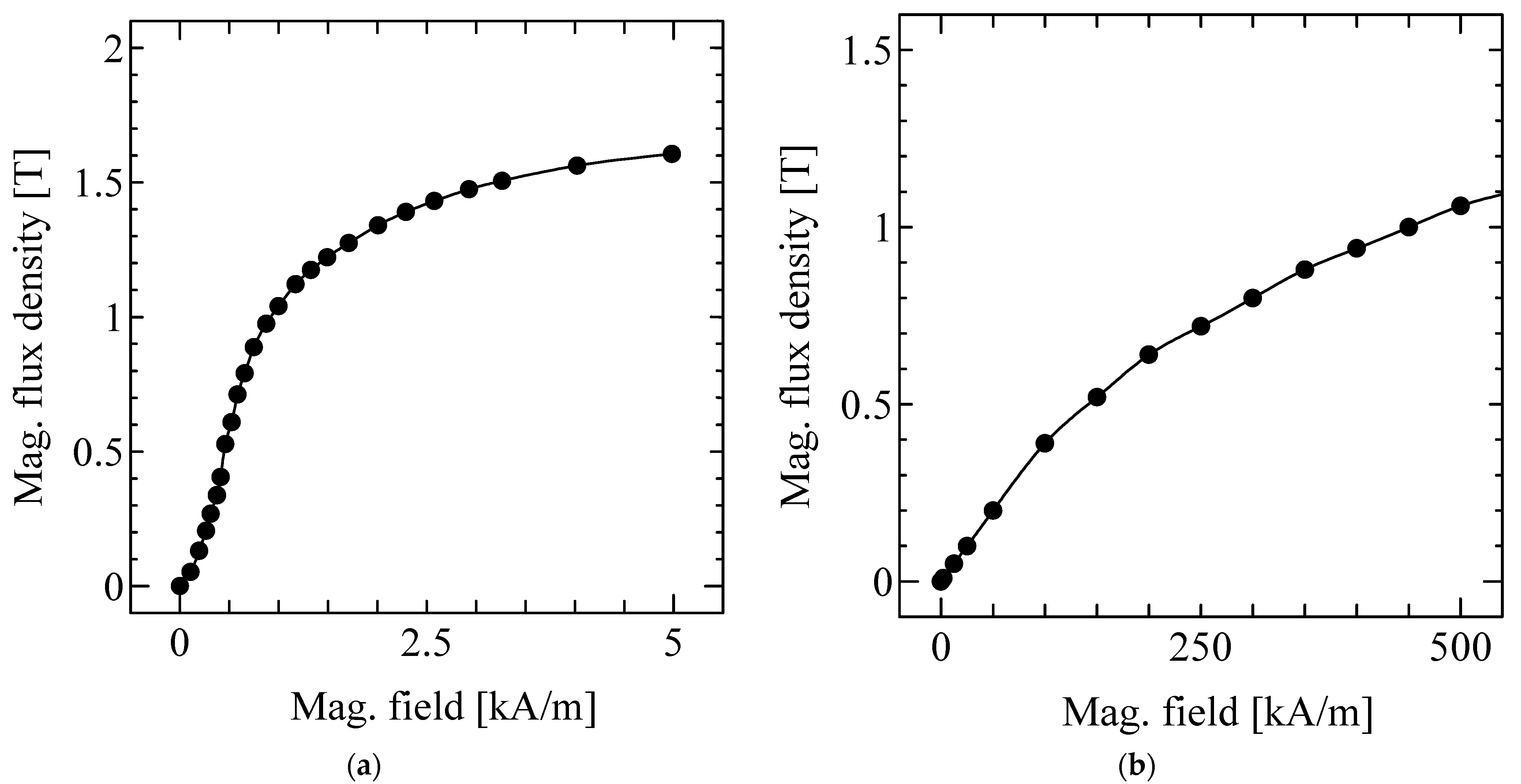
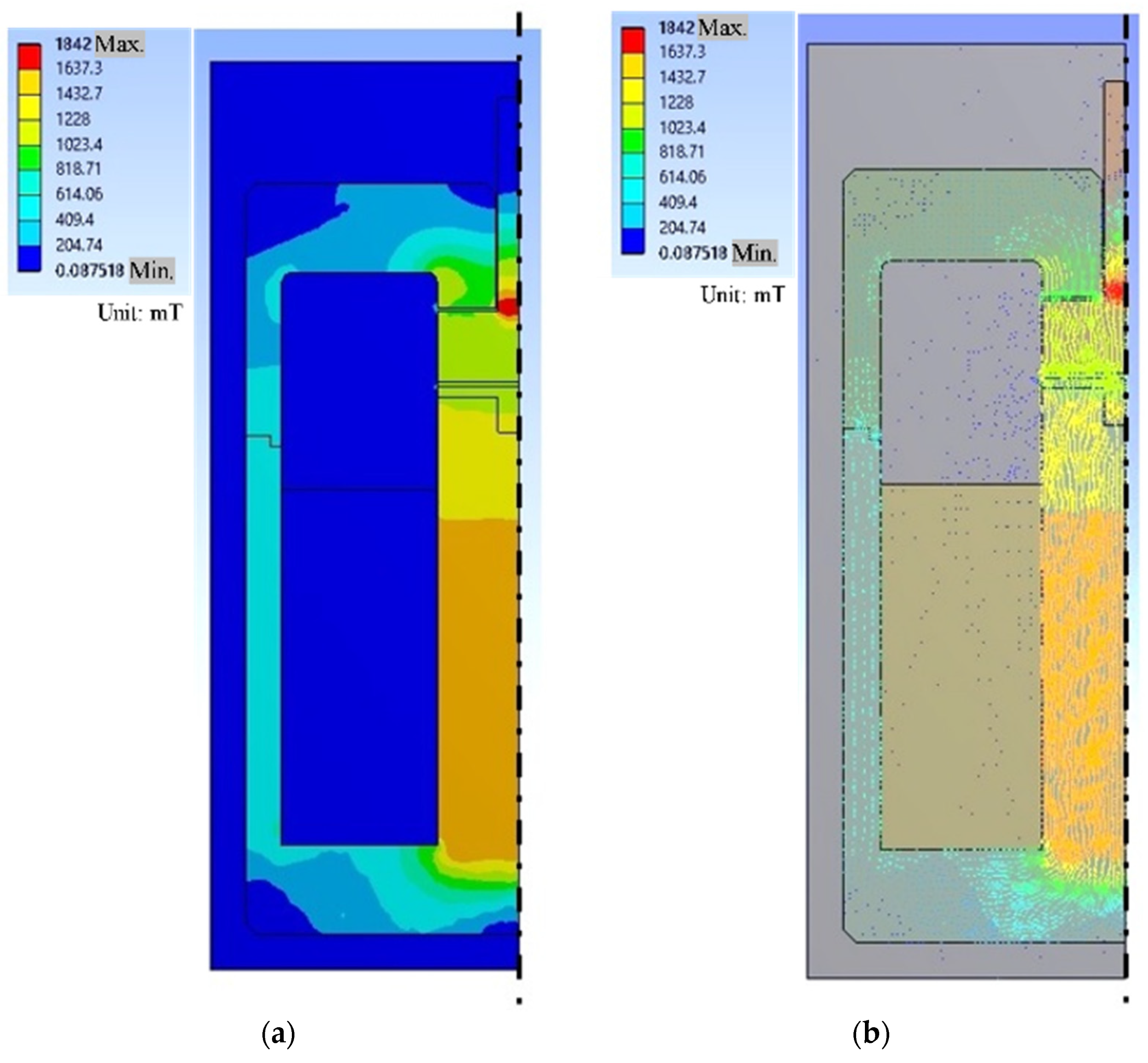
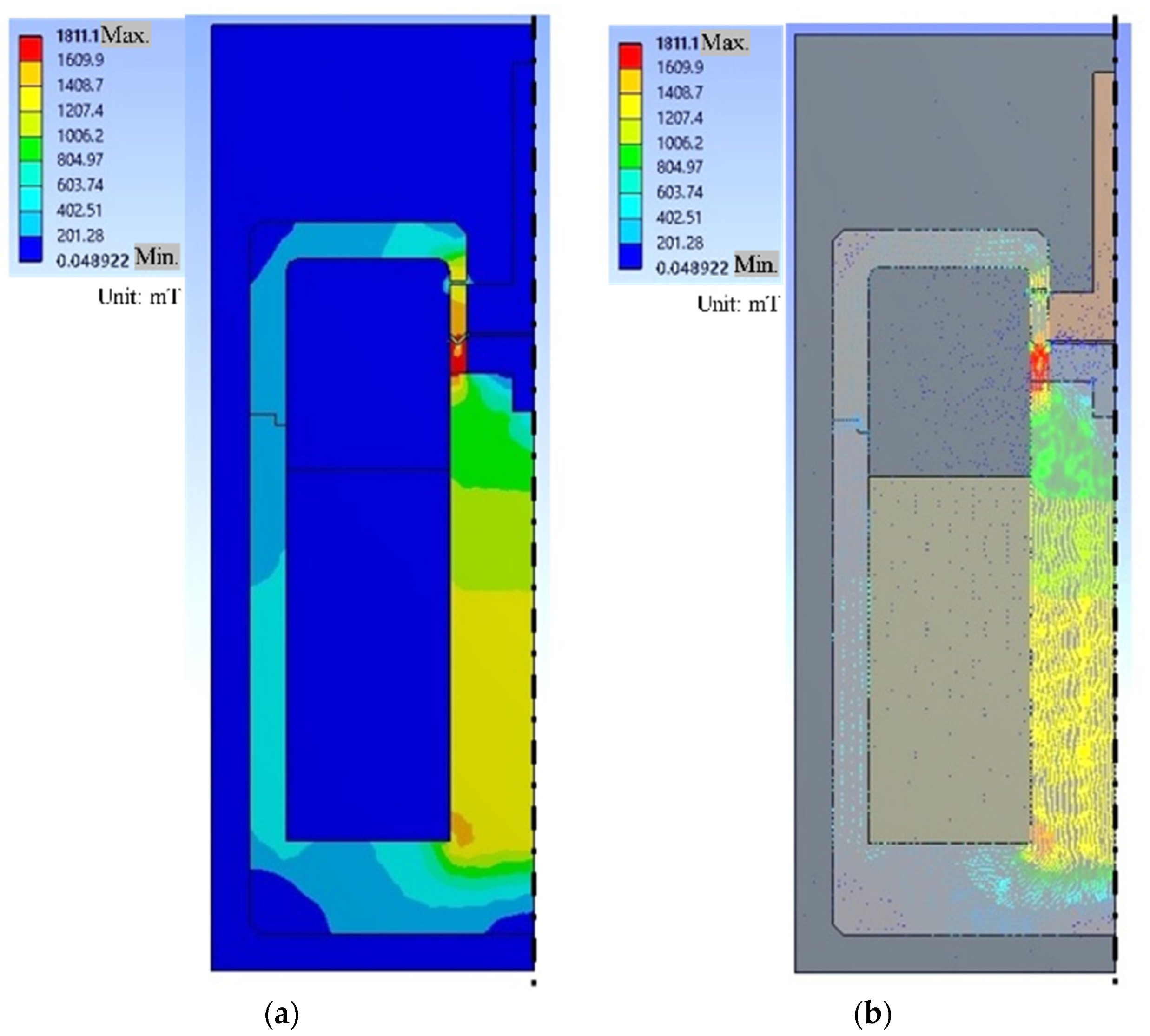
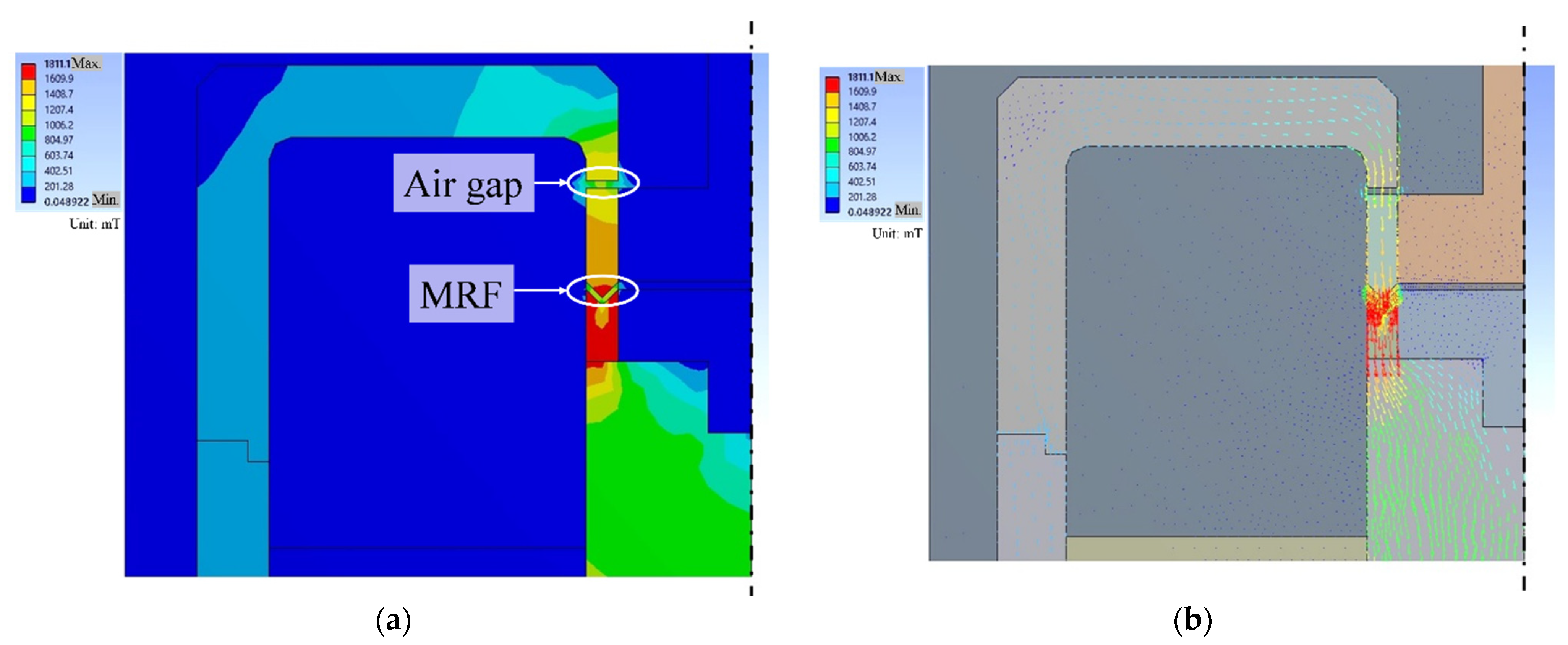
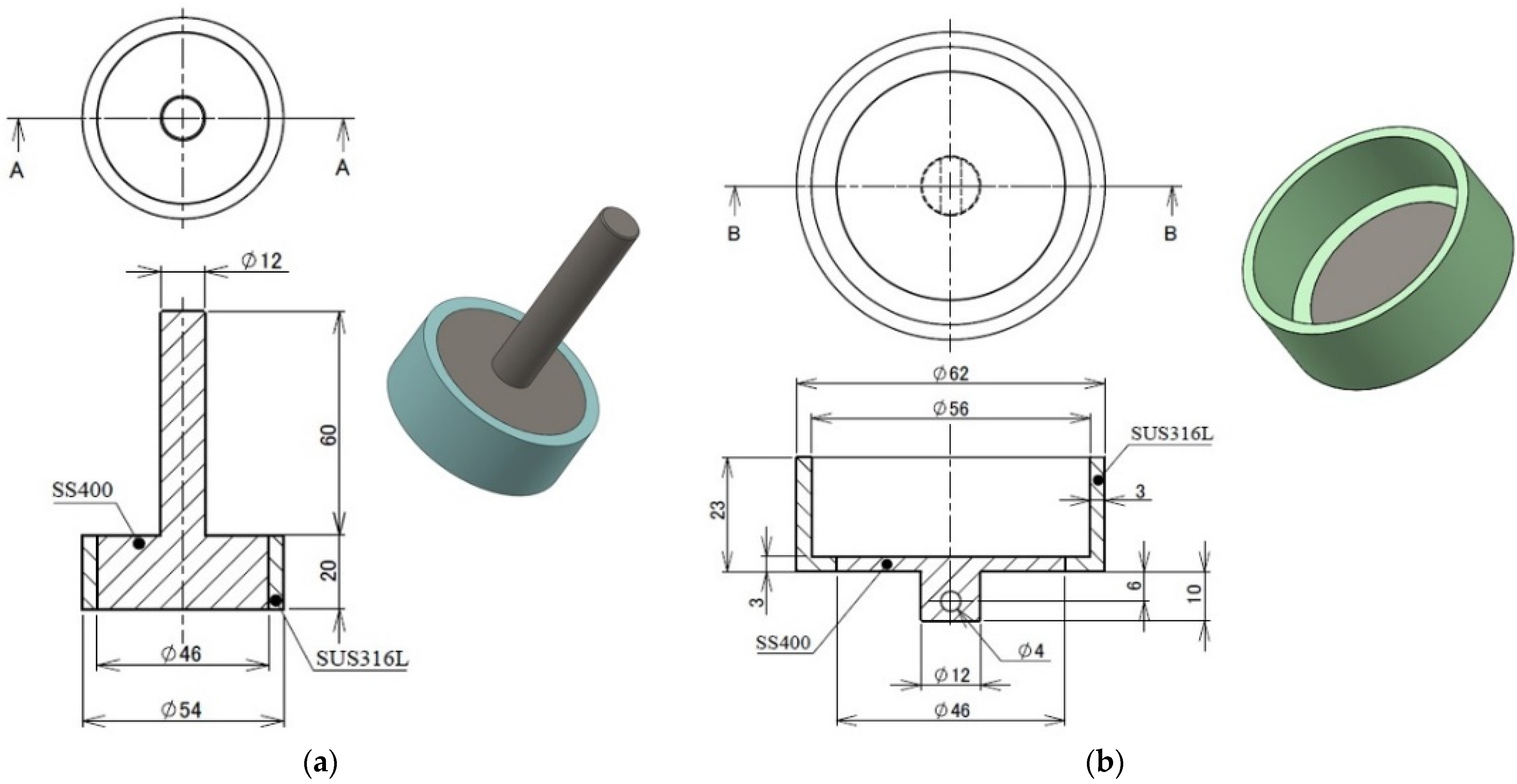
2.2. Rotor and Stator
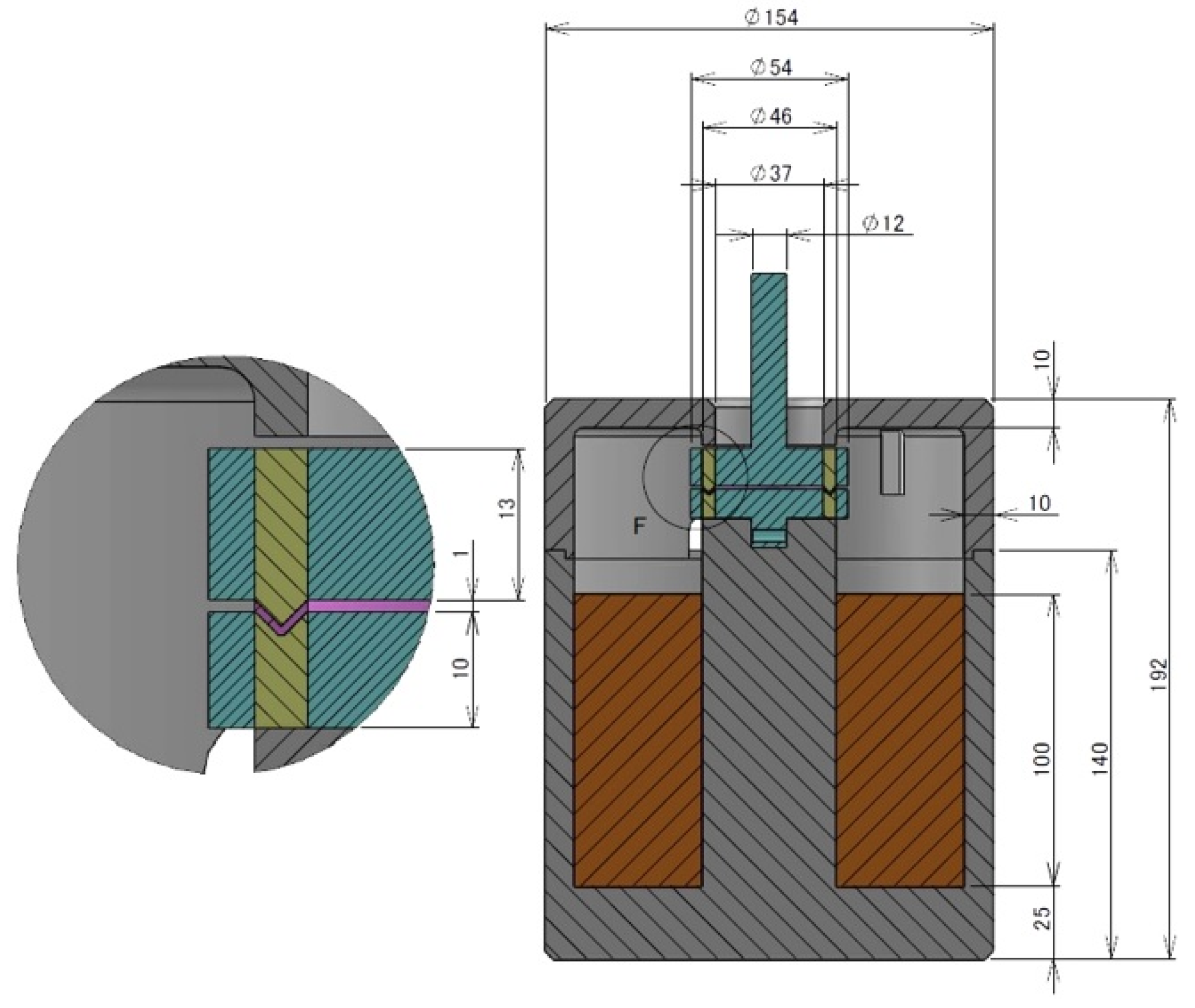
2.3. Design of Test Cell
3. Validation of Durability Test Device
3.1. Method
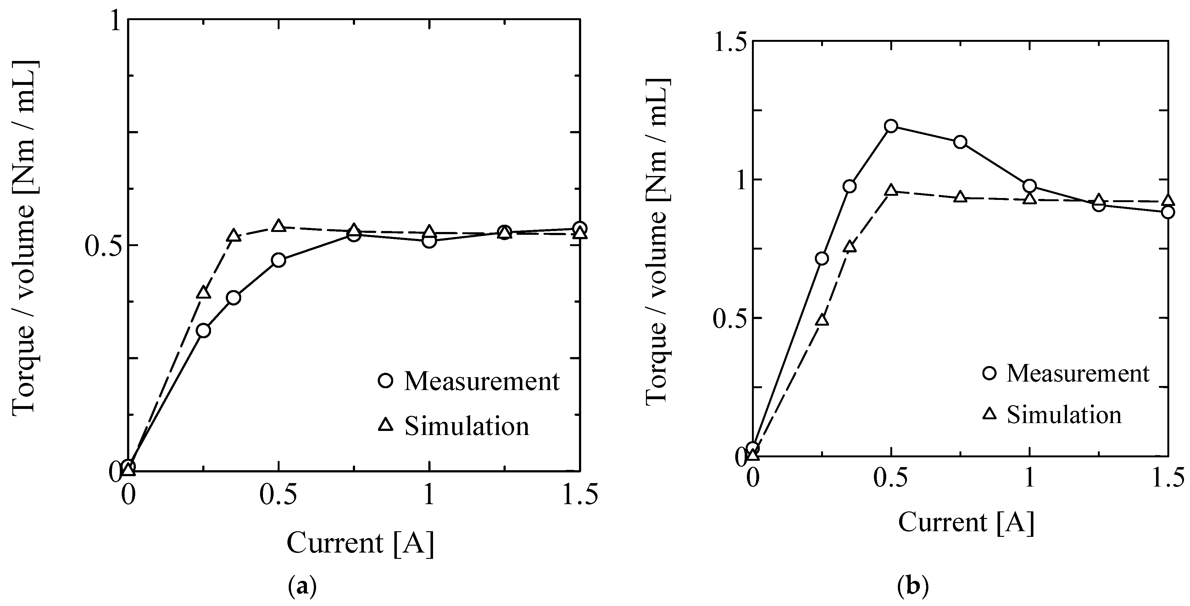
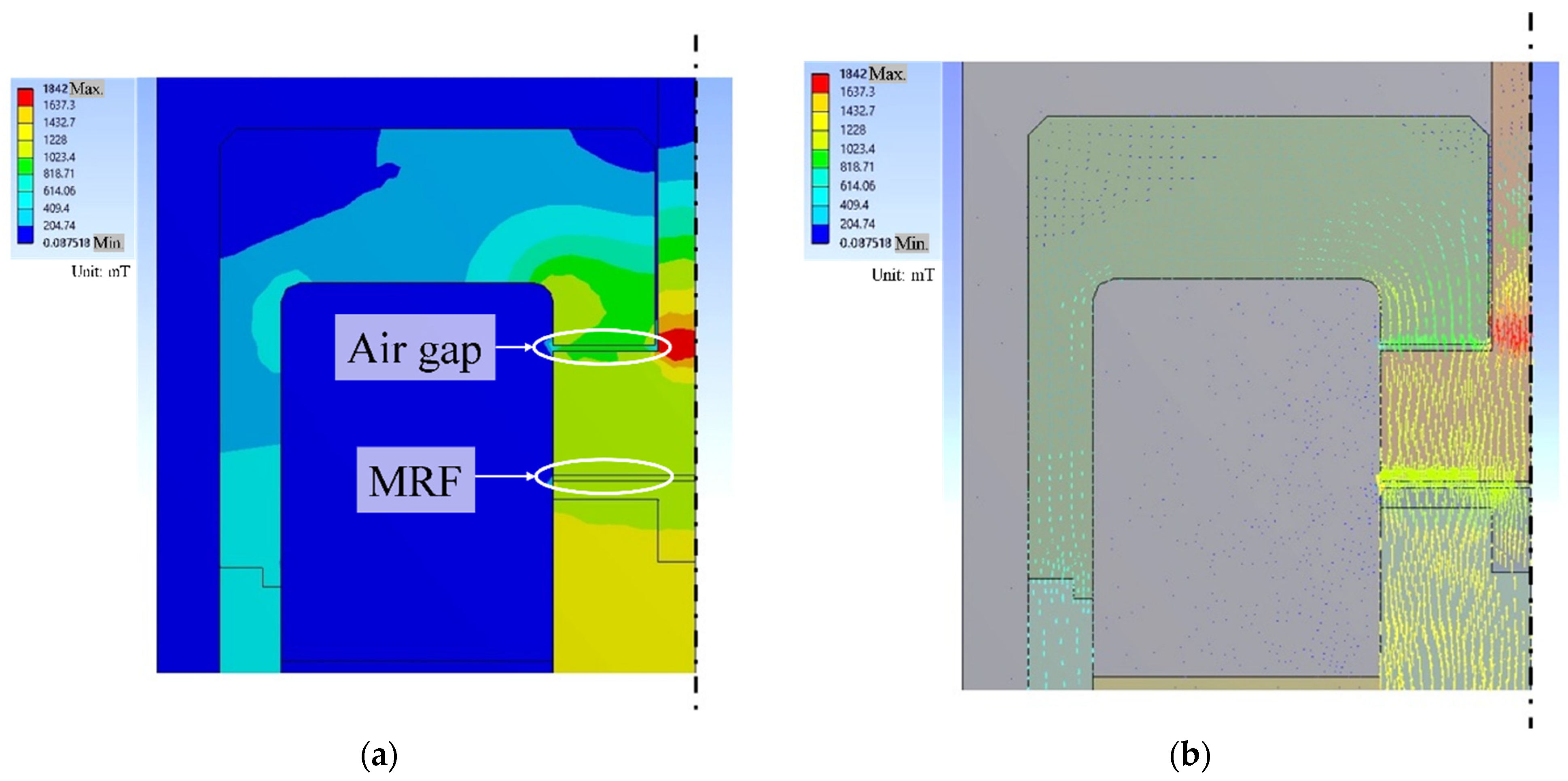
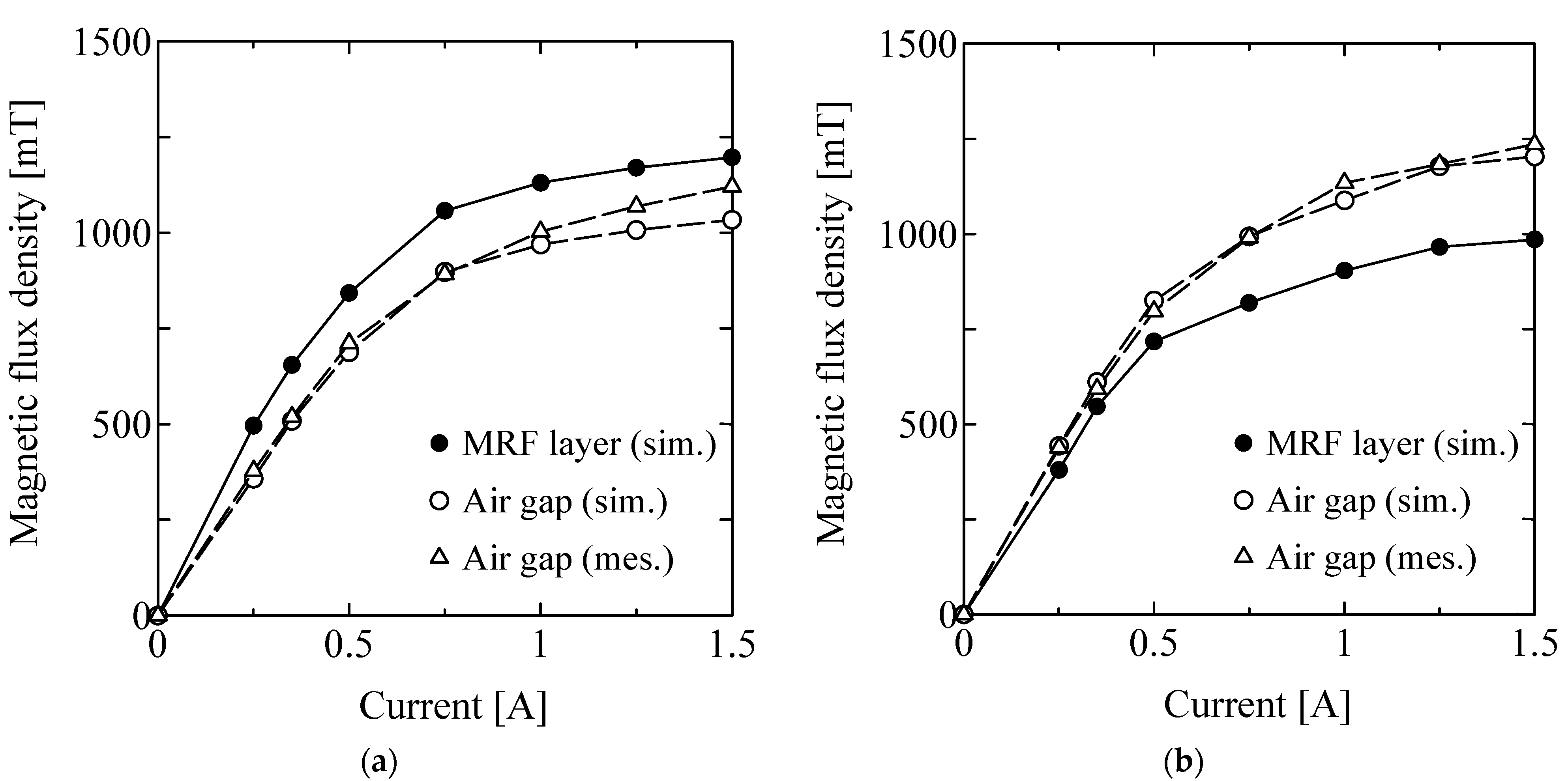
3.2. Result
3.3. Discussion
4. Long-Term Measurement
4.1. Method
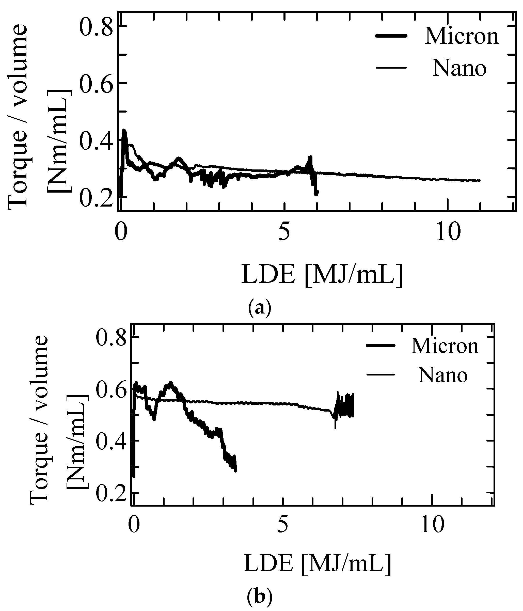
4.2. Result
4.3. Discussion
5. Conclusions
Author Contributions
Funding
Informed Consent Statement
Conflicts of Interest
References
- Carlson, J.D.; Jolly, M.R. MR fluid foam and elastomer devices. Mechatronics 2000, 10, 555–569. [Google Scholar] [CrossRef]
- Junichi, N.; Hiroya, A.; Takehito, K.; Junji, F.; Makio, N. Magnetorheology of colloidal dispersion containing Fe nanoparticles synthesized by the arc-plasma method. J. Magnet. Magnet. Mater. 2010, 322, 1868–1871. [Google Scholar]
- Il, J.M.; Min, W.K.; Hyong, J.C.; Namhui, K.; Chun-Yeol, Y. Fabrication of dopamine grafted polyaniline/carbonyl iron core-shelltyped microspheres and their magnetorheology. Colloids Surf. A Physicochem. Eng. Asp. 2016, 500, 137–145. [Google Scholar]
- Goncalves, F.; Carlson, J. Investigating the time dependence of the MR effect. Int. J. Mod. Phys. B 2007, 21, 4832–4840. [Google Scholar] [CrossRef]
- Kubík, M.; Šebesta, K.; Strecker, Z.; Jeniš, F.; Goldasz, J.; Mazůrek, I. Hydrodynamic response time of magnetorheological fluid in valve mode: Model and experimental verification. Smart Mater. Struct. 2021, 30, 125020. [Google Scholar] [CrossRef]
- Kwok, N.M.; Ha, Q.P.; Nguyen, M.T.; Li, J.; Samali, B. Bouc–Wen model parameter identification for an MR fluid damper using computationally efficient GA. ISA Trans. 2007, 46, 167–179. [Google Scholar] [CrossRef]
- Yazid, I.; Mazlan, S.; Imaduddin, F.; Zamzuri, H.; Choi, S.-B.; Kikuchi, T. An investigation on the mitigation of end-stop impacts in a magnetorheological damper operated by the mixed mode. Smart Mater. Struct. 2016, 25, 125005. [Google Scholar] [CrossRef]
- Choi, S.; Hong, S.; Cheong, C.; Park, Y. Comparison of field-controlled characteristics between ER and MR clutches. J. Intell. Mater. Syst. Struct. 1999, 10, 615–619. [Google Scholar] [CrossRef]
- Lee, U.; Kim, D.; Hur, N.; Jeon, D. Design analysis and experimental evaluation of an MR fluid clutch. J. Intell. Mater. Syst. Struct. 1999, 10, 701–707. [Google Scholar] [CrossRef]
- Kavlicoglu, B.; Gordaninejad, F.; Evrensel, C.; Liu, Y.; Kavlicoglu, N.; Fuchs, A. Heating of a high-torque magnetorheological fluid limited slip differential clutch. J. Intell. Mater. Syst. Struct. 2008, 19, 5–241. [Google Scholar] [CrossRef]
- Kikuchi, T.; Otsuki, K.; Furusho, J.; Abe, H.; Noma, J.; Naito, M.; Lauzier, N. Development of compact MR fluid clutch for human-friendly actuator. Adv. Robot. 2010, 24, 1489–1502. [Google Scholar] [CrossRef]
- Takehito, K.; Isao, A. Low inertia torque controllable device using magnetorheological fluid & umbrella-shaped rotor. Eng. Res. Exp. 2019, 1, 02502. [Google Scholar] [CrossRef]
- Tsujita, T.; Ohara, M.; Sase, K.; Konno, A.; Nakayama, M.; Abe, K.; Uchiyama, M. Development of a haptic interface using mr fluid for displaying cutting forces of soft tissues. In Proceedings of the 2012 IEEE International Conference on Robotics and Automation, Saint Paul, MN, USA, 14–18 May 2012; pp. 1044–1049. [Google Scholar]
- Fukuda, M.; Suzuki, Y. Elasticity Detection and Display of a Grasped Object Using Master-Slave System. In Proceedings of the 2012 SICE Annual Conference, Akita, Japan, 20–23 August 2012; pp. 1758–1762. [Google Scholar]
- Song, B.-K.; Oh, J.-S.; Choi, S.-B. Design of new 4-DOF haptic master featuring magnetorheological fluid. Adv. Mech. Eng. 2014, 6, 843498. [Google Scholar] [CrossRef] [Green Version]
- Takehito, K.; Junichi, N.; Syuichi, A.; Yuya, U. Response time of magnetorheological fluid-based haptic device. J. Intell. Mater. Syst. Struct. 2015, 27, 859–865. [Google Scholar] [CrossRef]
- Takehito, K.; Isao, A.; Tomoya, N.; Akinori, Y.; Tetsumasa, T. Twin-Driven actuator with multi-layered disc MR fluid clutches for haptics. J. Intell. Mater. Syst. Struct. 2021, 32, 1326–1335. [Google Scholar] [CrossRef]
- Takehito, K.; Tetsumasa, T.; Akinori, Y.; Asaka, I.; Isao, A. Haptic interface with twin-driven MR fluid actuator for teleoperation endoscopic surgery system. Actuator 2021, 10, 245. [Google Scholar] [CrossRef]
- Nishida, H.; Shimada, K.; Ido, Y. Effectiveness of using a magnetic compound fluid with a pulsed magnetic field for flat surface polishing. Int. J. Appl. Electromagnet. Mech. 2012, 39, 623–628. [Google Scholar] [CrossRef]
- Kordonskii, V.I.; Gorodkin, S.R. Magnetorheological polishing of optical surfaces. J. Opt. Technol. 2012, 79, 588. [Google Scholar] [CrossRef]
- Chaudhuri, A.; Wang, G.; Wereley, N.M.; Tasovksi, V.; Radhakrishnan, R. Substitution of micron by nanometer scale powders in magnetorheological fluids. Int. J. Mod. Phys. B 2005, 19, 1374–1380. [Google Scholar] [CrossRef]
- Wei, J.H.; Leng, C.J.; Zhang, X.Z.; Li, W.H.Z.; Liu, Y.; Shi, J. Synthesis and magnetorheological effect of Fe3O4-TiO2 nanocomposite. J. Phys. Conf. Ser. 2009, 149, 012083. [Google Scholar] [CrossRef] [Green Version]
- Park, B.J.; Park, C.W.; Yang, S.W.; Kim, H.M.; Choi, H.J. Core-shell typed polymer coated-carbonyl iron suspensions and their magnetorheology. J. Phys. Conf. Ser. 2009, 149, 012078. [Google Scholar] [CrossRef] [Green Version]
- Becnel, A.C.; Hu, W.; Wereley, N.M. High shear rate characterization of magnetorheological fluids. In Active and Passive Smart Structures and Integrated Systems 2012; International Society for Optics and Photonics: Bellingham, WA, USA, 2012. [Google Scholar]
- Xiaojie, W.; Faramarz, G. Study of magnetorheological fluids at high shear rates. Rheol. Acta 2006, 45, 899–908. [Google Scholar]
- Becnel, A.C.; Sherman, S.; Hu, W.; Wereley, N.M. Nondimensional scaling of magnetorheological rotary shear mode devices using the mason number. J. Magnet. Magnet. Mater. 2015, 380, 90–97. [Google Scholar] [CrossRef]
- Kikuchi, T.; Abe, I.; Inoue, A.; Iwasaki, A.; Okada, K. Characteristics of a magnetorheological fluid in high shear rate. Smart. Mater. Struct. 2016, 25, 115021. [Google Scholar] [CrossRef]
- Takesue, N.; Furusho, J.; Kiyota, Y. Fast response MR-fluid actuator. JSME Int. J. Ser. C 2004, 47, 783–791. [Google Scholar] [CrossRef] [Green Version]
- Kikuchi, T.; Furusho, J.; Yamaguchi, Y.; Kimura, S. Design of the High-Performance MR Brake and its Characteristics. In Proceedings of the 10th International Conference on ER Fluids and MR Suspensions, Lake Tahoe, USA, 18–22 June 2006; pp. 667–673. [Google Scholar]
- Wereley, N.M.; Chaudhuri, A.; Yoo, J.H.; John, S.; Kotha, S.; Suggs, A.; Radhakrishnan, R.; Love, B.J.; Sudarshan, T.S. Bidisperse magnetorheological fluids using Fe particles at nanometer and micron scale. J. Intell. Mater. Syst. Struct. 2006, 17, 393–401. [Google Scholar] [CrossRef]
- Hou, P.; Zhang, Q.J.; Wereley, N.M. Effect of storage and ball milling on the sedimentation and rheology of a novel magnetorheological fluid. J. Phys. Confer. Ser. 2009, 149, 012043. [Google Scholar]
- Carlos, G.S.; Tania, L.C.; Enrique, J.R.; Mircea, R.; Ulrich, S.S. Magnetorheological fluids based on ionic liquids. Adv. Mater. 2011, 20, 045001. [Google Scholar]
- Gabriel, C.; Oetter, G.; Kieburg, C.; Laun, M. Durability testing on magnetorheological fluids for clutch and brake applications. In Proceedings of the 12th International Conference on ER Fluids and MR Suspensions, Philadelphia, PA, USA, 16–20 August 2010; pp. 605–611. [Google Scholar]
- Carlson, J.D. What makes a good MR fluid? J. Intell. Mater. Syst. Struct. 2002, 13, 431–435. [Google Scholar] [CrossRef]
- Bigué, J.P.; Landry-Blais, A.; Pin, A.; Pilon, R.; Plante, J.S.; Chen, X.; Andrews, M. On the relation between the Mason number and the durability of MR fluids. Smart Mater. Struct. 2019, 28, 094003. [Google Scholar] [CrossRef]
- Ansgar, W.; Jurgen, M. Large-scale test bench for the durability analysis of magnetorheological fluids. J. Intell. Mater. Syst. Struct. 2012, 24, 1433–1444. [Google Scholar]
- Ulicny, J.C.; Balogh, M.P.; Potter, N.M.; Waldo, R.A. Magnetorheological fluid durability test–Iron analysis. Mater. Sci. Eng. A 2007, 443, 16–24. [Google Scholar] [CrossRef]
- Ulicny, J.C.; Hayden, C.A.; Hanley, P.M.; Eckel, D.F. Magnetorheological fluid durability test–Organics analysis. Mater. Sci. Eng. A 2007, 464, 269–273. [Google Scholar] [CrossRef]
- Isao, A.; Takehito, K.; Junichi, N. Durability test device for MR fluids with permanent magnet & V-shaped groove. Smart. Mater. Struct. 2017, 26, 054004. [Google Scholar] [CrossRef]


| Torque Sensor | UNIPULSE, UTMII (5 Nm) |
|---|---|
| Brushless Motor | Oriental motor, BLM5120-10B (120 W, 4 Nm, 1/10 geared) |
| Rated rotation speed | 300 rpm |
| Allowable torque | 3.4 Nm (3000 rpm) |
| Total size (B × W × H) | 180 mm × 300 mm × 575 mm |
| Maximum current | 6.8 A |
| Turning Number | 2300 Turn |
|---|---|
| Wire diameter | 1 mm |
| Maximum current | 3.9 A |
| Core material | Structural steel |
| Diameter of Fe Particles | 6–7 μm |
|---|---|
| Solvent | hydrocarbon oil + dispersant |
| Relative density | 2.20–2.24 |
| Particle fraction | 20 vol% |
| Viscosity @ 25 °C | 0.082 Pas |
| Yield shear stress @ 25 °C | 0.159 Pa |
| Micron MRF | Nano MRF | |
|---|---|---|
| Diameter of Fe particles | 6–7 μm | 80–120 nm |
| Solvent | hydrocarbon oil + dispersant | hydrocarbon oil + dispersant |
| Relative density | 2.20–2.24 | 2.20–2.24 |
| Particle fraction | 20 vol% | 20 vol% |
| Viscosity @25 °C | 0.082 Pas | 5.58 Pas |
| Yield shear stress @25 °C | 0.159 Pa | 5.80 Pa |
| Parallel Plate | V-Shaped Plate | |||
|---|---|---|---|---|
| Micron | Nano | Micron | Nano | |
| Time (hour) @ 1 MJ/mL | 42.6 | 38.7 | 23.7 | 23.6 |
| Time (hour) @ 2 MJ/mL | 86.9 | 81.7 | 47.4 | 47.5 |
| Ave. torque b/w 1–2 MJ/mL (Nm/mL) | 0.300 | 0.309 | 0.561 | 0.554 |
| S.D. torque b/w 1–2 MJ/mL (Nm/mL) | 0.0228 | 0.00511 | 0.0452 | 0.00231 |
| Rate of variability (%) | 7.62 | 1.66 | 8.05 | 0.418 |
Publisher’s Note: MDPI stays neutral with regard to jurisdictional claims in published maps and institutional affiliations. |
© 2022 by the authors. Licensee MDPI, Basel, Switzerland. This article is an open access article distributed under the terms and conditions of the Creative Commons Attribution (CC BY) license (https://creativecommons.org/licenses/by/4.0/).
Share and Cite
Kikuchi, T.; Abe, I.; Ueshima, Y.; Akaiwa, S.; Tsuji, H. Development of Durability Test Device for Magnetorheological Fluids with Two Types of Rotors and Their Long-Term Torque Characteristics. Actuators 2022, 11, 142. https://doi.org/10.3390/act11060142
Kikuchi T, Abe I, Ueshima Y, Akaiwa S, Tsuji H. Development of Durability Test Device for Magnetorheological Fluids with Two Types of Rotors and Their Long-Term Torque Characteristics. Actuators. 2022; 11(6):142. https://doi.org/10.3390/act11060142
Chicago/Turabian StyleKikuchi, Takehito, Isao Abe, Yuya Ueshima, Shuichi Akaiwa, and Hitoshi Tsuji. 2022. "Development of Durability Test Device for Magnetorheological Fluids with Two Types of Rotors and Their Long-Term Torque Characteristics" Actuators 11, no. 6: 142. https://doi.org/10.3390/act11060142
APA StyleKikuchi, T., Abe, I., Ueshima, Y., Akaiwa, S., & Tsuji, H. (2022). Development of Durability Test Device for Magnetorheological Fluids with Two Types of Rotors and Their Long-Term Torque Characteristics. Actuators, 11(6), 142. https://doi.org/10.3390/act11060142