Article

Dynamic Performance Analysis and Design of Vortex Array Grippers

1
Taiwan Instrument Research Institute, National Applied Research Laboratories, Hsinchu 30076, Taiwan
2
Department of Aeronautics and Astronautics, National Cheng Kung University, Tainan 70101, Taiwan
*
Author to whom correspondence should be addressed.
Actuators 2022, 11(5), 137; https://doi.org/10.3390/act11050137
Submission received: 9 March 2022 / Revised: 3 May 2022 / Accepted: 14 May 2022 / Published: 17 May 2022

Abstract

:
In this study, the performance of a vortex array gripper was numerically investigated based on the pressure distribution on the surface of a gripped object and the resulting suction force. An analysis of the suction force generated by a single-vortex gripper was performed to determine the geometric parameters for providing a good suction force and subsequently, for the vortex array gripper configuration. Array grippers consisting of two- and four-vortex grippers were studied. For dual-vortex grippers, the generated suction forces of various inlet air configurations with different vortex gripper distances are illustrated. The pros and cons of all types of air supply and the influence of positive pressure formed by outlet airflow interaction were examined. The analysis of quad-vortex grippers also revealed that the suction force could be increased by reducing the outlet flow interaction between the grippers using the placement of exhaust vents. Thus, the installation of array grippers can be arranged in a more compact form to increase the total suction force per unit operation area with uniformity.

1. Introduction

The demand for advanced production technologies has increased owing to the rapid development of the semiconductor industry. Robotic manipulators are conventional appliances used for gripping and positioning in various industries. In the production process involving silicon wafer manipulation, the workpiece may be damaged by surface scratching and static electricity from frequent contact with end-effectors, leading to defective products. To prevent quality defects owing to contact with the gripper, noncontact grippers have been proposed as a preferable solution. Commercially available noncontact grippers are used to grip thin films, copper sheets, PCBs, and LED glass screen panels.
The air-flow-based gripping method is a conventional technique used in noncontact grippers. Bernoulli levitation and vortex levitation are the main types of pneumatic noncontact methods. For example, the Bernoulli gripper uses airflow to adhere to a workpiece. As the name implies, this is based on the Bernoulli airflow principle. A high-velocity airstream flows radially and forms a low-static-pressure region between the gripper and workpiece. Subsequently, it enables contactless gripping within a given range gap. The Bernoulli gripper also shows good stability without using a control loop and reduces maintenance expenses [1,2]. Moreover, Bernoulli grippers can be applied to food production processes, such as in the handling of fruits and vegetables, to reduce damage [3]. The other gripping method is based on vortex levitation [4], which feeds air into a vortex chamber through a tangential nozzle to generate a high-speed vortex flow. Because of the centrifugal force, a negative pressure is generated in the center of the vortex. The negative pressure distributed over the central region of the vortex chamber results in a suction force, and the positive pressure around the gap passage prevents air from flowing into the vortex chamber, which maintains the negative pressure in the gripper. The gripper designed based on the vortex levitation principle, as shown in Figure 1, is called a vortex gripper [5].
The distribution of the negative pressure in the vortex chamber varies with the inlet mass flow rate and clearance gap between the gripper and workpiece. An adequate clearance gap is required to maintain a stable suction force. If the workpiece departs from the equilibrium position, a higher mass flow rate can be supplied to obtain a higher suction force and recover a stable condition. However, the vortex is dispersed and the flow is reversed if the clearance gap exceeds the limitation. This phenomenon is similar to that observed in cyclones. The lowest pressure occurs at the center of the cyclone. Therefore, producing a vortex in the vortex gripper generates a notable negative-pressure region.
In recent years, some researchers have devoted their efforts to studying noncontact grippers. Ma et al. [6] numerically examined the flow characteristics of the pressure distribution and bearing capacity. Their study demonstrated that the lifting force increases as the inlet mass flow rate increases. In addition, the effects of the gap thickness are also discussed. As the gap thickness increases, the lifting force initially increases and then decreases to a stable value. This indicates that the optimal lifting force can be obtained by maintaining a suitable gap thickness. Feng et al. [7] numerically predicted the suction force of vortex grippers and pressure distribution. This study proposed the relations between the suction force and several parameters to improve the performance of arc/circular inner channel grippers. Iio et al. [8] investigated the relationship between the sucking pressure and flow dynamics. Measurements were performed for the pressure and flow field in the vortex chamber, and indicated that the performance of the vortex levitation is strongly affected by the gap height between the vortex gripper and the workpiece. Li et al. [9] conducted numerical and experimental studies on vortex grippers and provided scientific insights into flow phenomena and flow structure. Moreover, the influence of clearance variation on the performance was investigated. Li and Kagawa [10] proposed a new noncontact gripper called swirl gripper. They clarified the mechanism of this gripper and showed that it can maintain stable levitation in the levitation zone.
Considering the wafer size, the dimensions of the manipulator end-effector should be designed accordingly. The suction force of the small grippers may be insufficient for large wafers. Therefore, an array gripper is used for handling large wafers at low cost. The suction force is proportional to the inlet mass flow rate. In this study, the suction force was considered as a performance index, and the geometric parameters of the vortex chamber were studied. First, a single-vortex gripper was studied to determine the best combination of the design parameters. Then, dual-vortex grippers were constructed based on this single-vortex gripper model for array gripper studies. The interactions of airflow in different layout patterns were examined for different distances between each gripper, and the maximum suction force per unit area was realized. The analysis of quad-vortex grippers also revealed that the suction force could be increased by reducing the outlet flow interaction between the grippers using the placement of exhaust vents.
The outline of this article is as follows: The numerical method and key system parameters applied in this study are introduced in Section 2. In Section 3, a parametric analysis is performed. The effects of geometric parameters of a single-vortex gripper on resulting suction force and pressure distributions are discussed. Subsequently, the layouts of gripper arrays and the resulting pressure distributions are investigated. The different layout designs with exhaust vents on quad-vortex array grippers are also proposed to improve suction force generation. In Section 4, the conclusions are made and future studies are addressed.

2. Numerical Method

In this study, the governing equations of mass, momentum, energy, and RNG k − ε turbulence model were employed. Assumptions of an ideal gas and compressible flow were made because of the high-pressure condition at the inlet boundary. The mass flow rate and pressure outlet boundaries were set at the inlet and outlet, respectively. The commercial software ANSYS FLUENT was used to solve the governing equations. The present study is based on the SIMPLEC algorithm. Pressure and velocity correction schemes were implemented in the model algorithm to arrive at a converged solution when both the pressure and velocity satisfied the momentum and continuity equations, and the under-relaxation scheme was employed to avoid divergence in the iterative solutions.
Based on a literature survey and to make the study more practical, the following parameter values were selected for the rest of the numerical study: D2 = 17 mm, d = 1 mm, h = 10 mm, H2 = 2 mm, and H3 = 1.2 mm. Because the mass flow rate condition was applied to the inlet boundary, the inlet velocity varied with the diameter of the inlet nozzle (d). Simulations were performed within a confined range of parameters to obtain a good suction force for the vortex gripper.

3. Results and Discussions

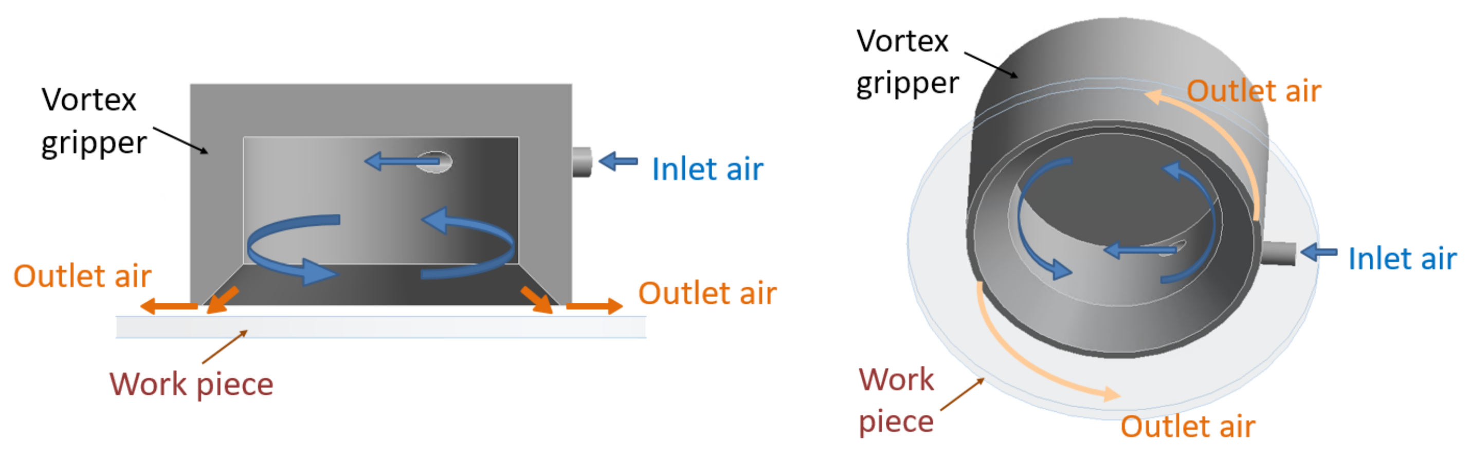
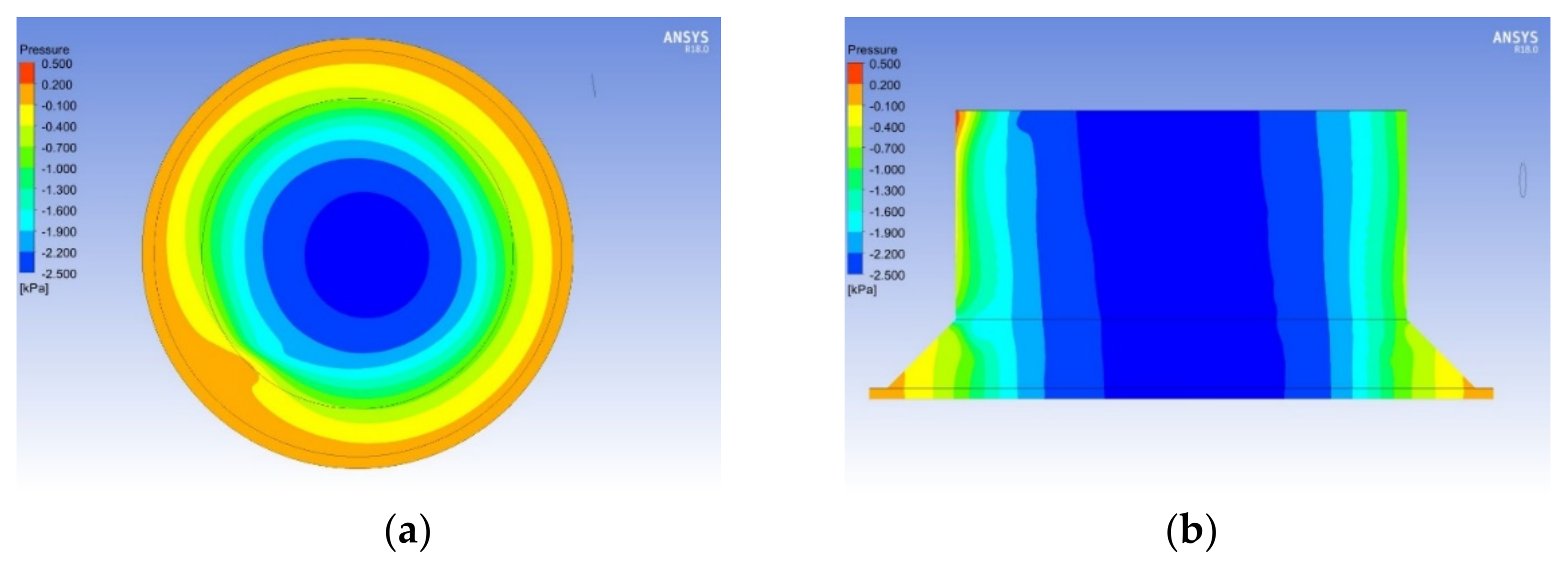
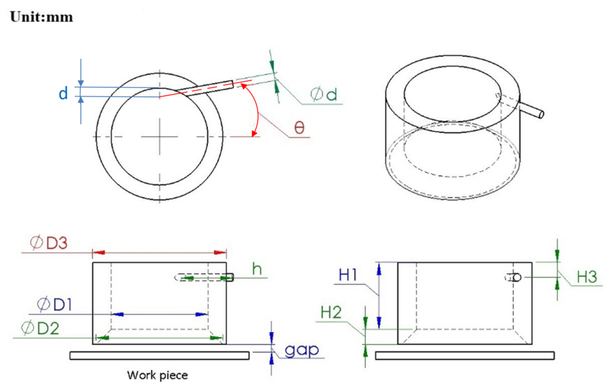
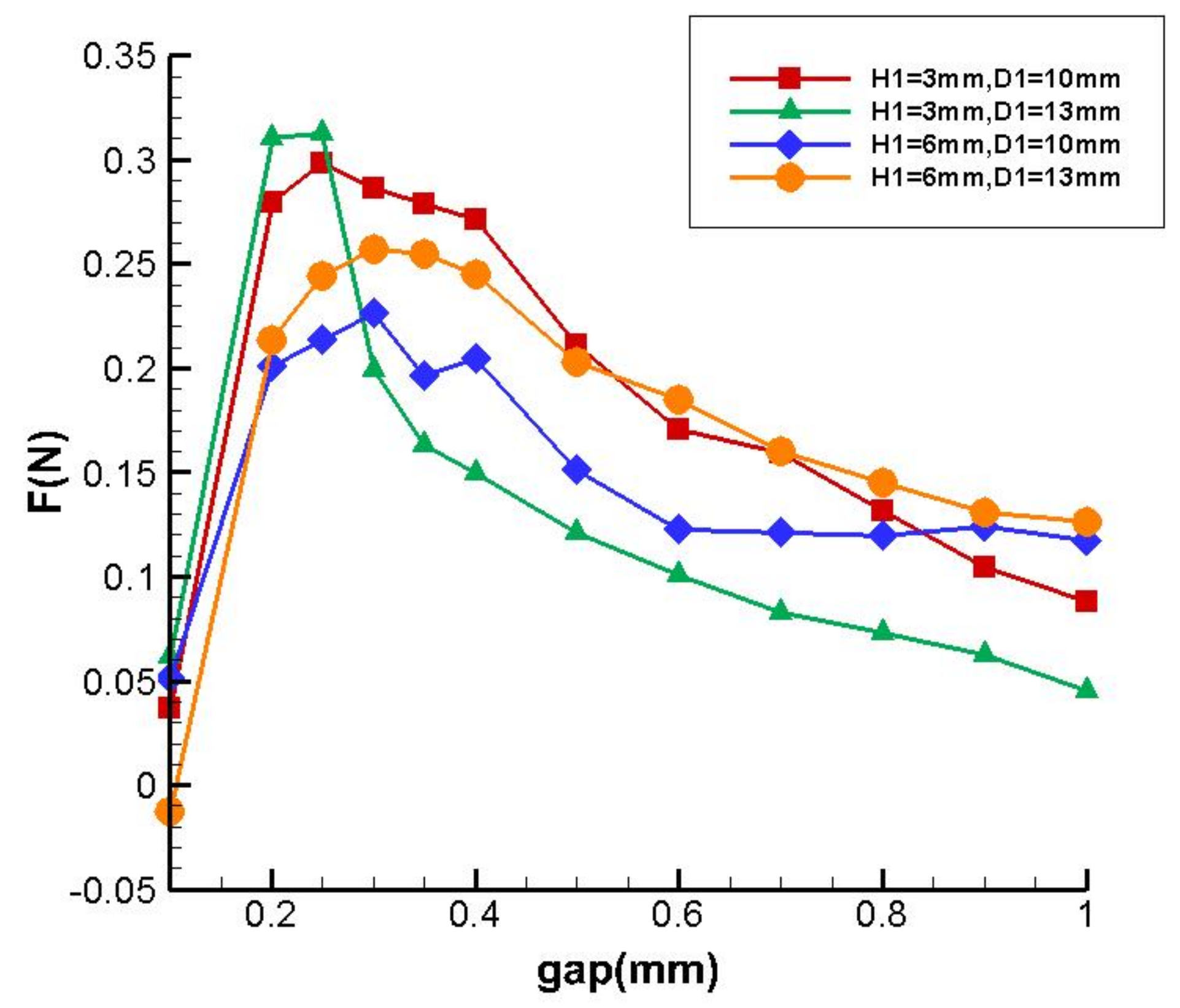
3.1. Geometric Parameters and Performance of a Single Vortex Gripper

First, the influence of the inlet angle θ was studied. Referring to Figure 2, the geometric parameters were as follows: D1 = 13 mm, D3 = 18 mm, H3 = 1.2 mm, gap = 0.3 mm, d = 1.0 mm. The inlet mass flow rate Q was 2 × 10⁻⁴ kg/s. The resulting suction force with respect to H1 and θ is presented in Table 1. The maximum suction force occurred at θ = 10° for both H1 values. Hence, θ = 10° was applied in the following studies. To investigate the suction force at different gap values up to 1 mm, four cases with different H3 and D1 were studied under mass flow rate conditions of Q = 2 × 10⁻⁴ kg/s. As shown in Figure 3, the largest suction force occurred at gap = 0.3 ± 0.1 mm for all cases. Therefore, a gap of 0.3 mm was chosen for the suction force evaluation in the following design studies.
Table 2 shows the resulting suction forces for different Q, D1, and H1. When Q = 1 × 10⁻⁴ kg/s, the suction force of the vortex gripper was too weak to grip effectively. In contrast to the case with Q = 1 × 10⁻⁴ kg/s, the case with Q = 3 × 10⁻⁴ kg/s generated a stronger suction force. However, an impractical inlet velocity of 311 m/s (i.e., Mach 0.91) was reached and was not suitable for the physical model applied in this study. Considering the stable suction force and referring to the literature, Q = 2 × 10⁻⁴ kg/s was used for the studies. Table 2 also shows that the suction force increased with decreasing H1. However, too small a H1 leads to low numerical accuracy or even divergence owing to a large dimension ratio. Considering the simulation effort and reasonable magnitude of the suction force, H1 = 6 mm was adopted. The geometric parameters with D1 = 13 mm and H1 = 6 mm under a mass flow rate of Q = 2 × 10⁻⁴ kg/s obtained a suction force of 0.257 N, which was the largest among the cases. The pressure distribution of the vortex gripper chamber is shown in Figure 4, where the outer edge region shows a high pressure relative to the center region and the pressure decreases gradually toward the center and develops a negative-pressure region for generating the suction force. In the subsequent discussions, the suction force is calculated according to the pressure distribution on the lower boundary surface of the gripper.

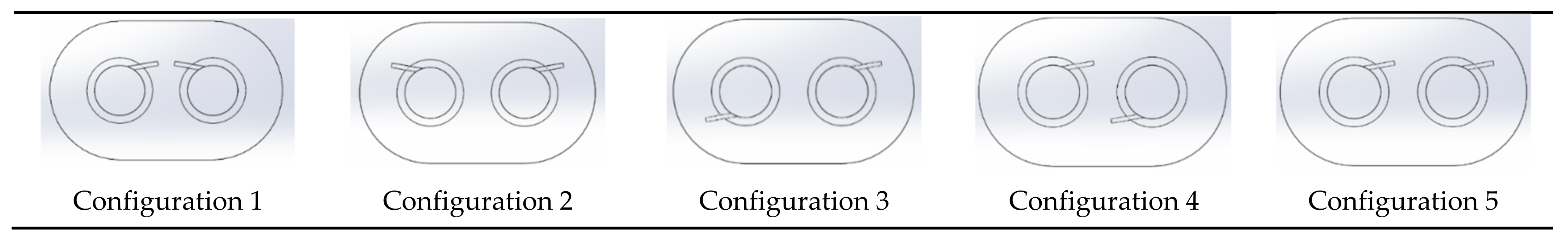
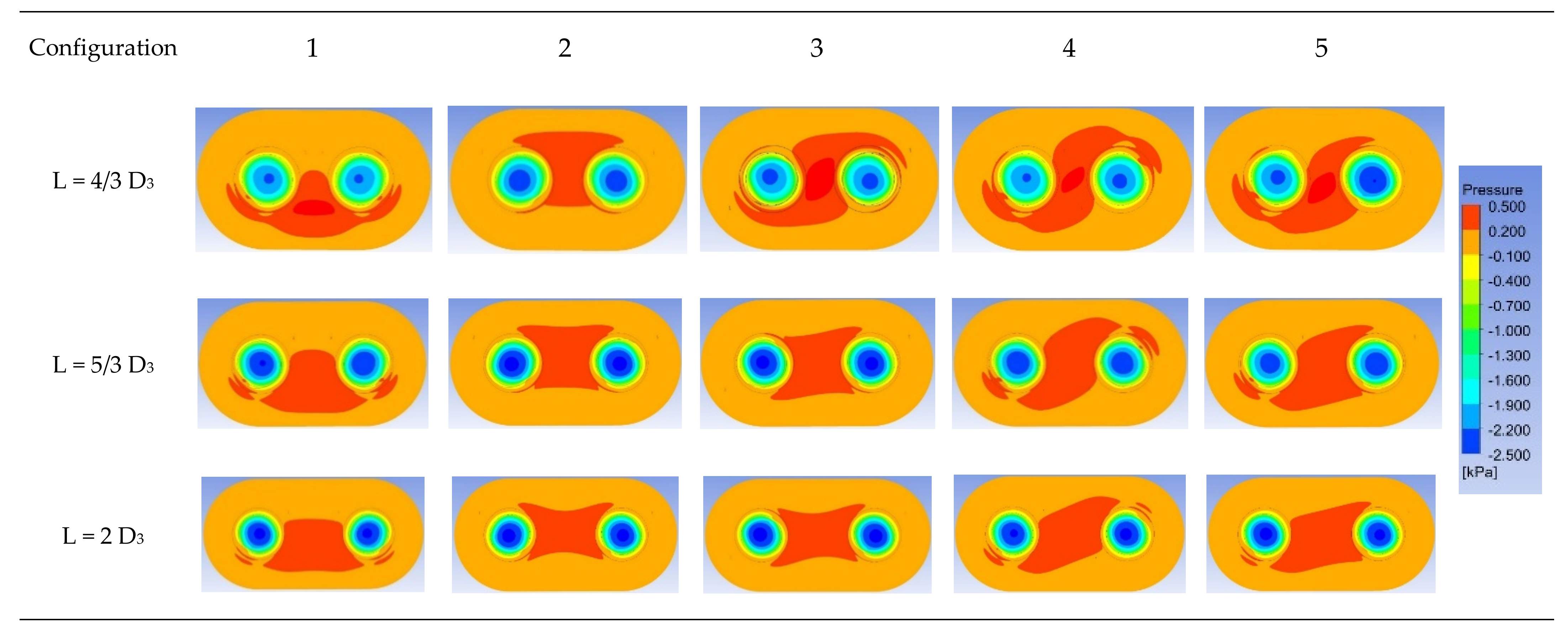
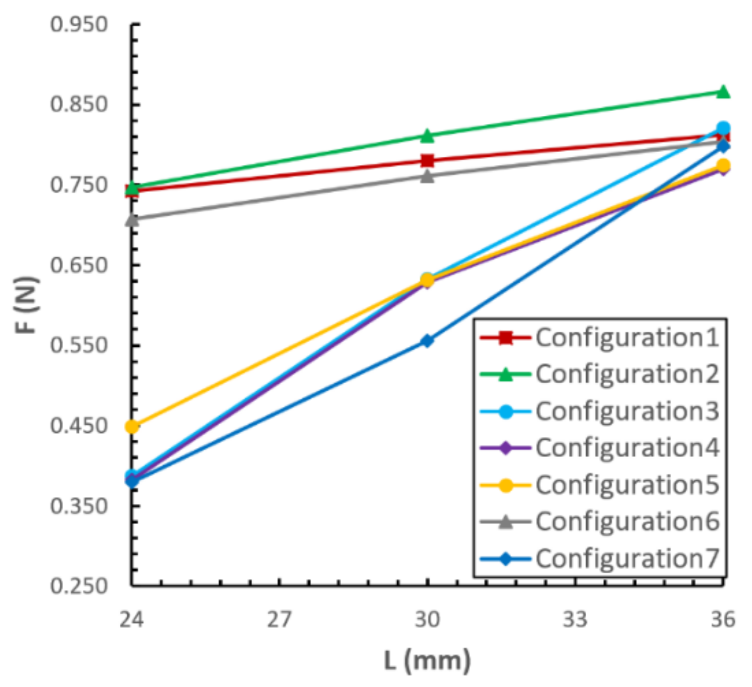
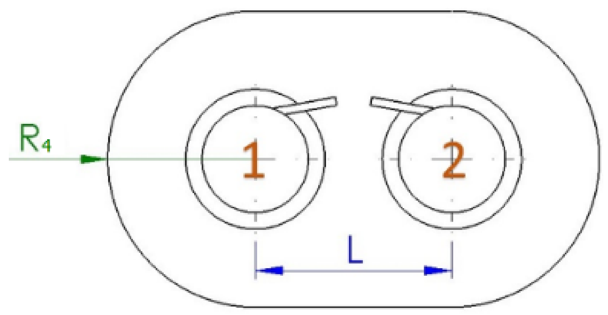
3.2. Dual-Vortex Grippers

Based on the preference single-vortex gripper described in the previous section, dual- and quad-vortex array grippers can be arranged as shown in Figure 5 and Figure 6, where L is the distance between the grippers, and R4 is the radius for determining the coverage of the end-effector. In this configuration, R4 is defined as twice the diameter D3 to determine the outlet boundary. Five inlet configurations were proposed for the simulation, as shown in Figure 7.
Let D3 be the characteristic length for setting the distance (L) between the vortex grippers. The suction forces corresponding to L = 24 mm (4/3 D3), 30 mm (5/3 D3), and 36 mm (2 D3) are shown in Figure 8. This reveals that the larger the distance between the vortex chambers, the larger the suction force. However, the coverage area increases as the distance of the vortex chamber increases. The rate of increase of the suction force is less than that of the area. To assess the gains and losses, L = 4/3 and D3 = 24 mm resulted in a larger average suction force per unit area compared to the others.
The pressure distributions for the different inlet configurations are shown in Figure 9. It is observed that the interaction of the flow creates a positive pressure region in the center between the two grippers. An increase in the distance (L) between the two grippers attenuates the positive pressure region. Because the layouts from configurations 1 to 4 have mirror symmetry or symmetry, the performances of the grippers are similar. Configuration 2 exhibits the best performance. Although configuration 5 also shows good performance in terms of the total suction force, it has a significant suction force difference between the grippers. This may cause the gripper to malfunction owing to an object attitude imbalance. Investigating the trends of streamlines of dual-vortex grippers with L = 4/3 D3 as shown in Figure 10, configuration 2 shows less flow interference of the two vortices and results in a better suction force compared to the other configurations.

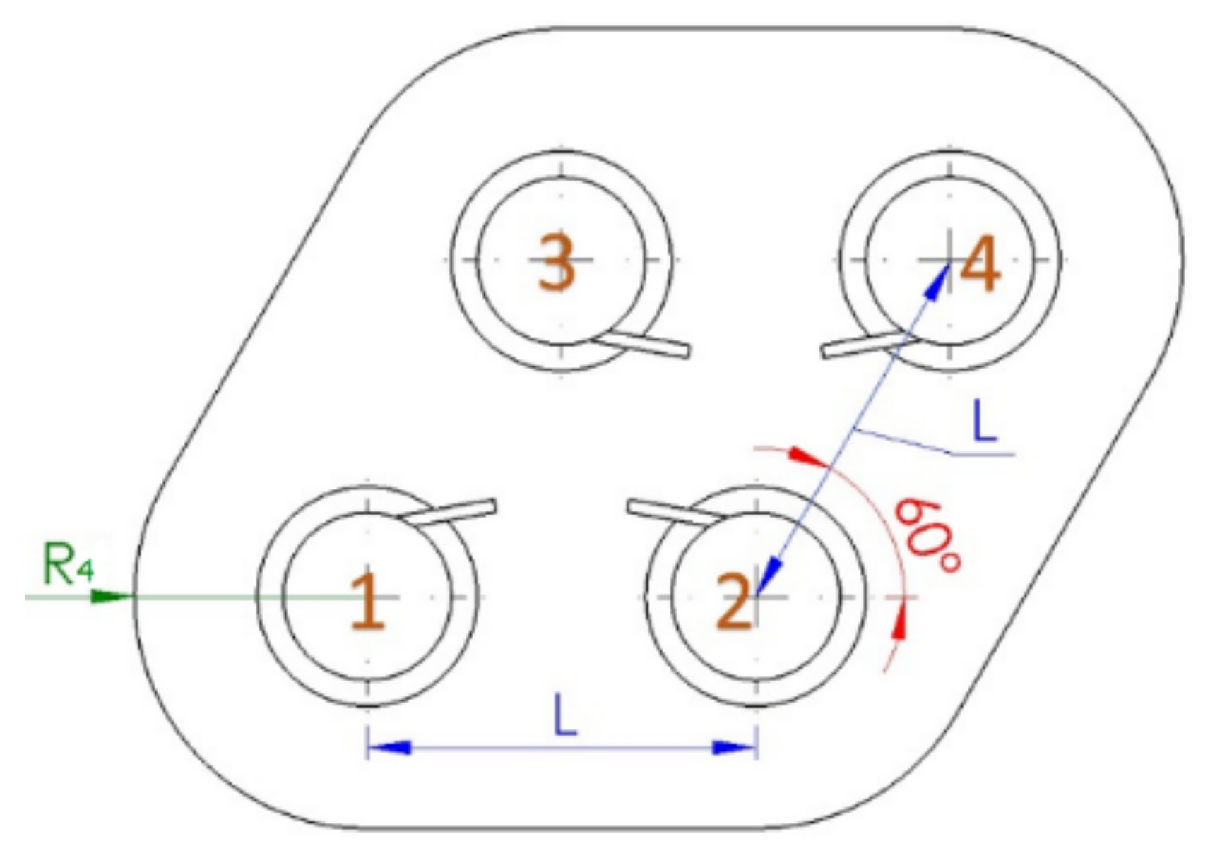
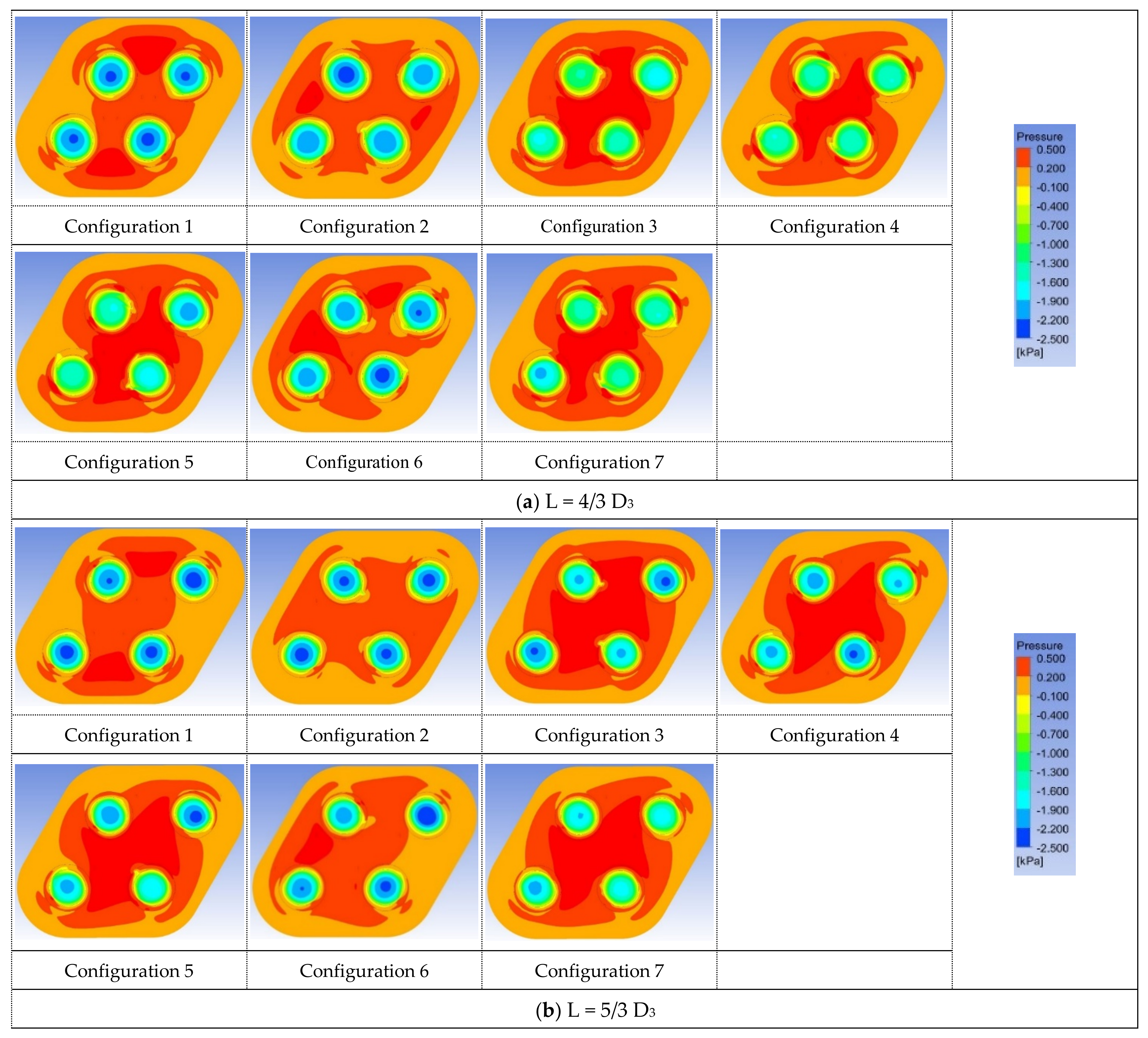
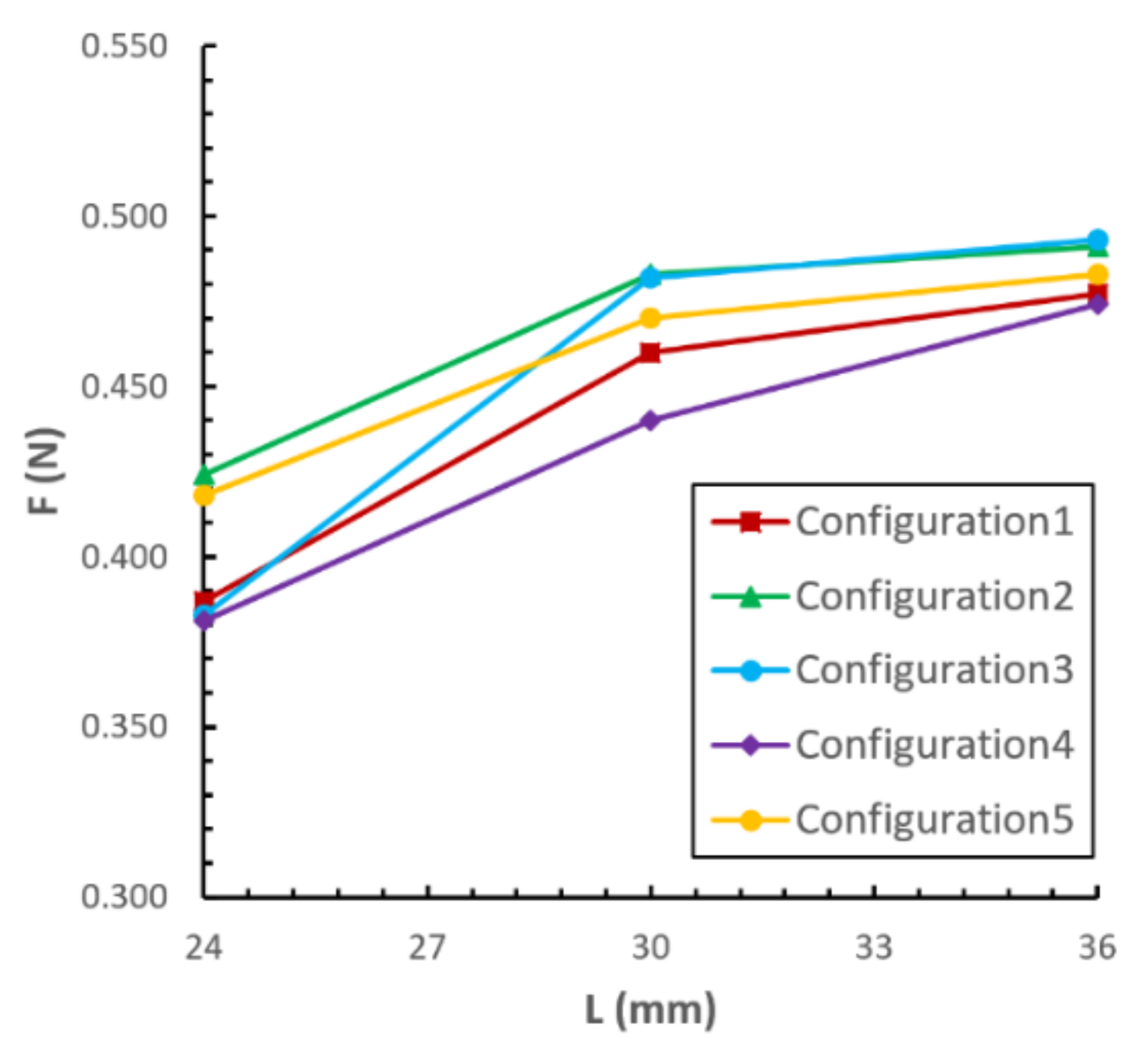
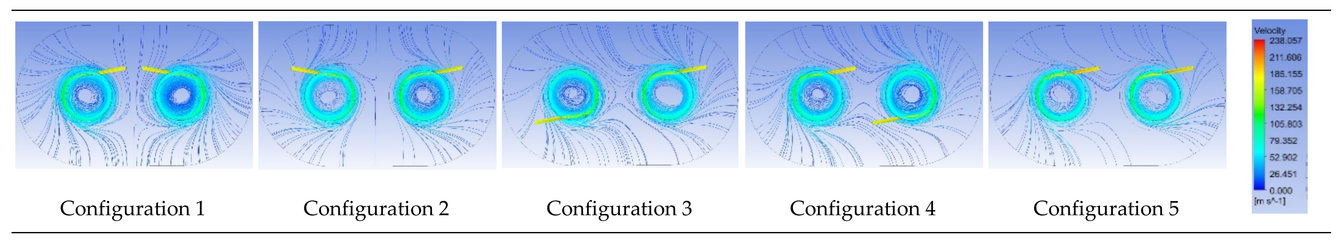
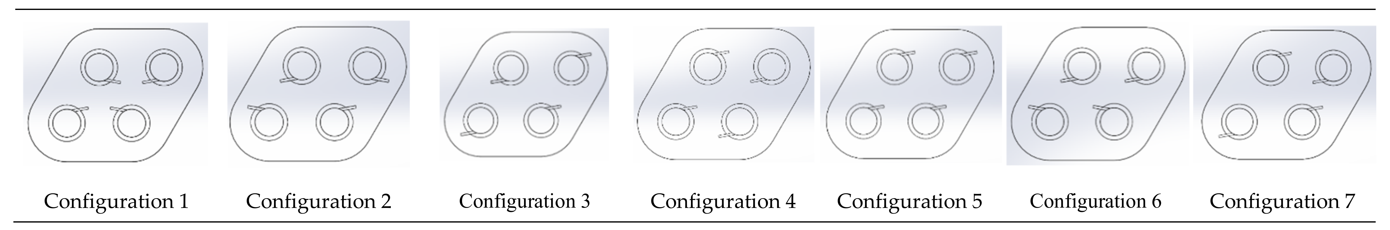
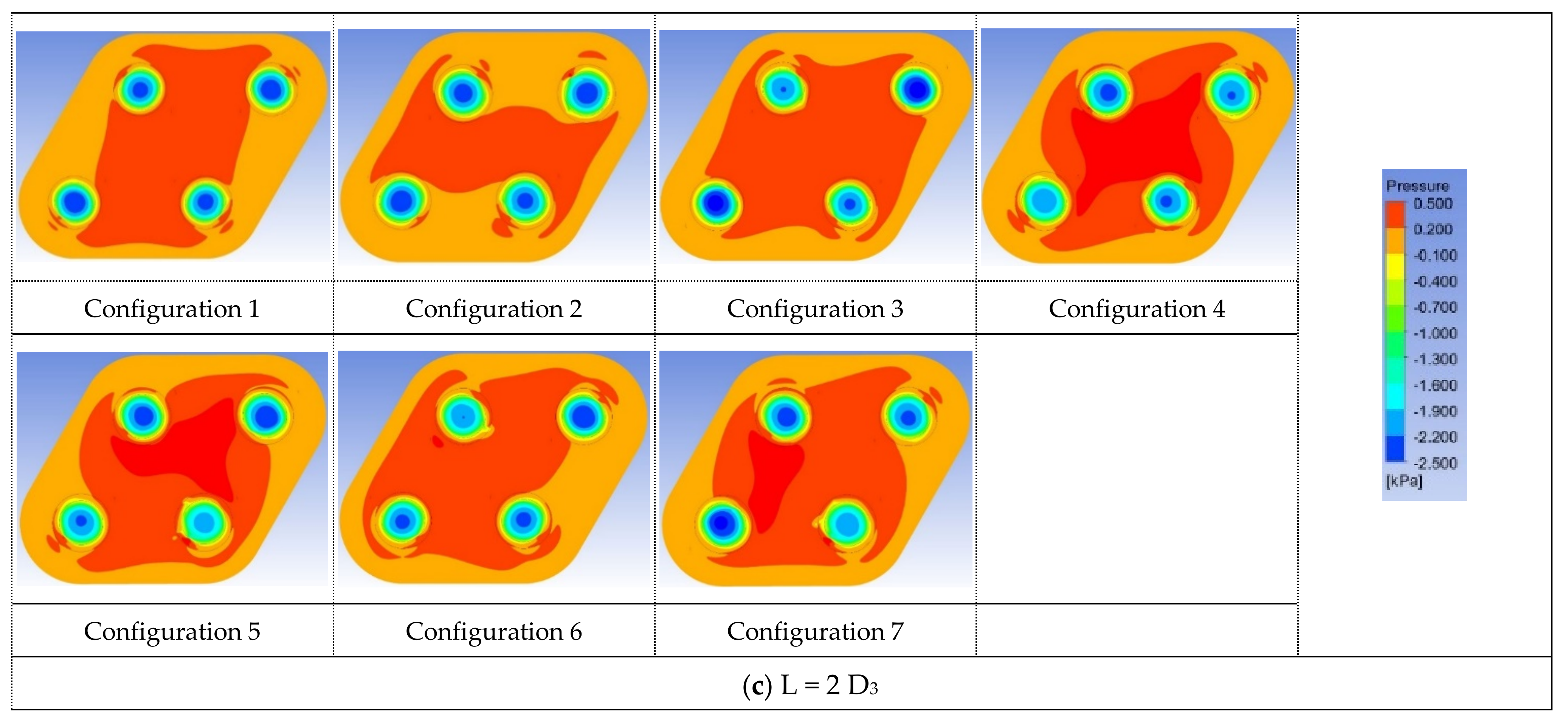
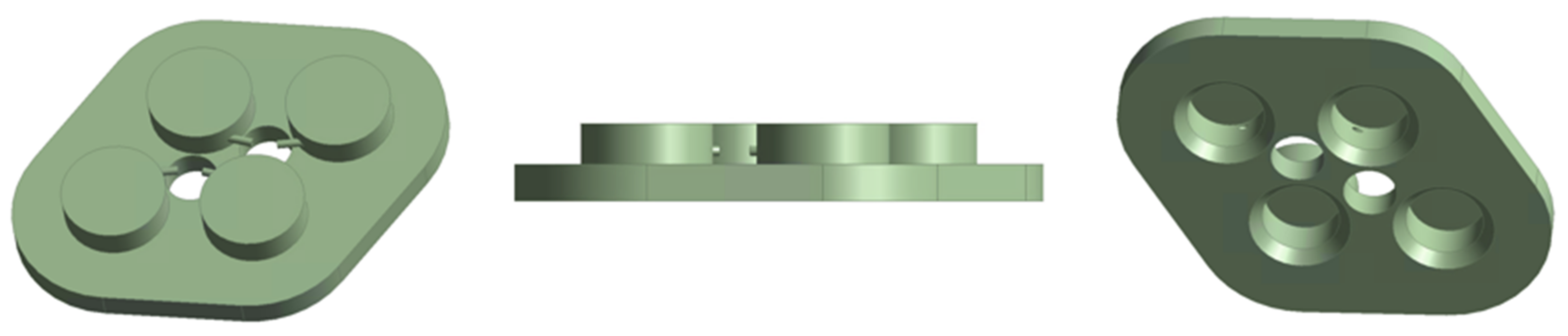
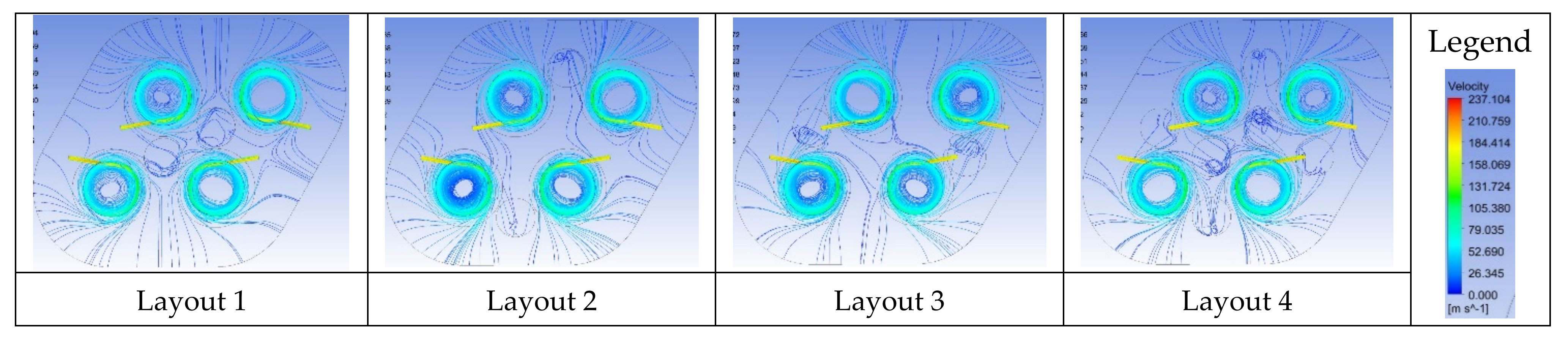
3.3. Quad-Vortex Array Grippers

In this section, quad-vortex array grippers with different configurations are discussed. Two equilateral triangles were used to construct a parallelogram, and four vortex grippers were placed at the four corners, as shown in Figure 11. Similar to the dual-vortex grippers, R4 = 2 D3 was applied. Seven different inlet directions were considered. The results revealed that a larger suction force is obtained with larger L, as shown in Figure 12. In the aspect of the suction force per unit area, configurations 1 and 2 provide the best suction force for L = 4/3 D3. The pressure distributions of the array grippers are shown in Figure 13. It reveals that all configurations generate a high-pressure region in the center owing to outlet flow interaction. Configurations 1 and 2 generate balanced suction forces with similar negative pressure distributions in each vortex chamber.

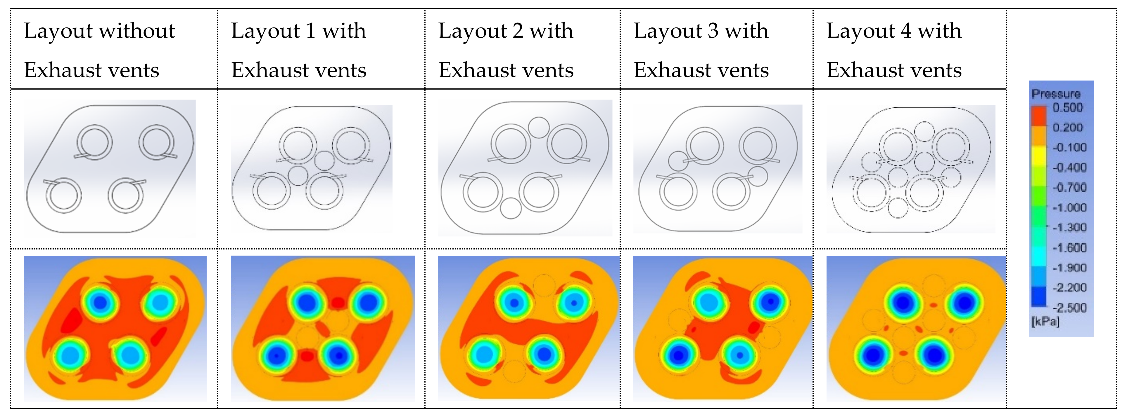
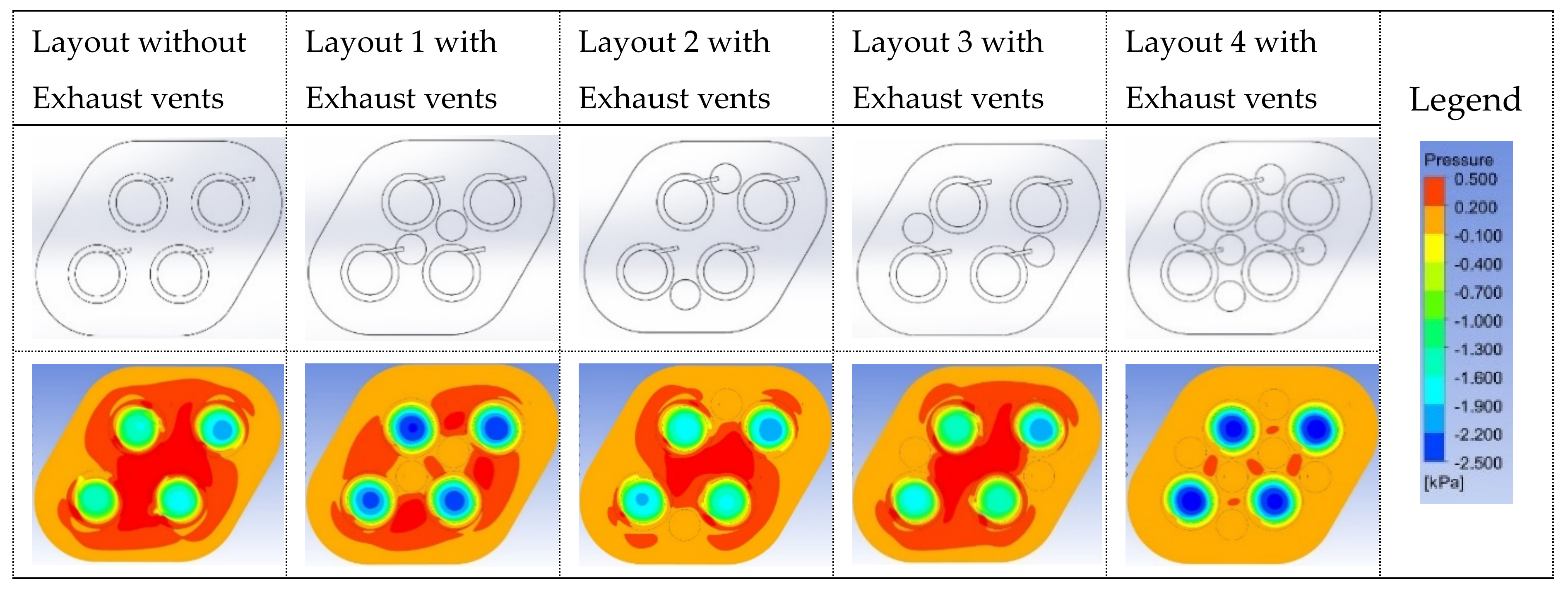
3.4. Quad-Vortex Array Grippers with Exhaust Vents

The results of the previous section show that the interaction of airflow affects the quad-vortex array grippers in all configurations and generates a positive pressure region at the center of the vortex array. The distribution of the positive pressure region is influenced by the exhaust flow. In this section, the exhaust vents are placed in the high-pressure region to investigate their influence on the suction force, and a change in the positive pressure distribution is demonstrated.
Consider the quad-vortex array grippers of configuration 2 (L = 4/3 D3) as an example. Exhaust vents can be placed where there is a positive pressure. Considering the stiffness and dimensions fitness, the diameter and height of the exhaust vents were assigned as diameter D e = 9 mm and height H e = 5 mm. The structure of quad-vortex array grippers with exhaust vents is shown in Figure 14. The geometric model and pressure distribution with exhaust vents at different locations are shown in Figure 15. It indicates that the performance of the array gripper is improved in view of the negative pressure intensity enhancement and positive-pressure region reduction. The positive pressure region almost vanishes in the layout with six exhaust vents.
The performances of the quad-vortex array grippers with and without exhaust vents are listed in Table 3. This reveals that the suction force increases when exhaust vents are applied. With two-exhaust-vent cases, the exhaust vents at the center enhanced the suction force per unit area by 22%, and a fully installed case with six vents increased the suction force per unit area by 36%.
The streamlines of the quad-vortex array grippers with exhaust vents for configuration 2 are shown in Figure 16. It depicts that the working fluid is discharged into the exhaust vents and causes variations in the streamlines. In the previous discussion, it was found that the optimum suction force per unit area occurred when the airflow was exhausted from the center of the array gripper. Central vents provide a shorter passage for exhaust air; therefore, the suction force per unit area was the best among the cases with two vents. The streamlines in the case of the six vents show that the exhaust air diverged uniformly.
Considering extended pattern manufacturing, exhaust vents were also introduced to the vortex array grippers of configuration 5, which consists of vortex grippers with the same inlet direction. The results in the previous section show that configuration 5 only produced 60% of the suction force of configuration 2 without exhaust vents. Figure 17 shows the pressure distribution of the quad-vortex grippers with exhaust vents in different vent layouts. The exhaust vent sizes were the same as those for configuration 2, that is, diameter De = 9 mm in and height He = 5 mm.
The pressure distribution reveals that the two exhaust vents applied at the center led to a significant improvement in the negative pressure region, and the suction force per unit area increased by 89%, as shown in Table 4. The increment in the suction force per unit area was up to 122% with six exhaust vents. Compared to configuration 2, the suction force difference per unit area was less than 2% in the six-exhaust-vent designs. Configuration 5 is a practical design for constructing grippers with a large size and a large number of vortex grippers.

4. Conclusions

The suction force of the vortex array grippers was studied numerically. The influence of the geometry and operating conditions on the pressure distribution was investigated to achieve a higher suction force. A parametric analysis was employed to obtain a preferable single-vortex gripper with a higher suction force, which was then used to construct the array grippers. Dual- and quad-vortex grippers of different layouts based on different vortex gripper distances between and inlet air directions were investigated. The suction force per unit area can reach a good value with appropriate exhaust vent placement. The results of this study are beneficial to the design of array grippers with a large number of vortex grippers and are summarized as follows:
(1)
The lower the height of the vortex chamber (H1), the better the suction force generated. However, a large numerical error is induced by a very small vortex chamber, and the pressure of the vortex chamber is highly sensitive to the gap between the gripper and workpiece when the vortex chamber is insufficient.
(2)
With regard to the vortex array grippers, the suction force of each gripper reaches a maximum when the vortex gripper distance is sufficiently large. However, the suction force per unit area may not be the largest, owing to the increase in the effective area.
(3)
For both dual-vortex grippers and quad-vortex array grippers, a mirror-like layout design with L = 24 mm (4/3 D3) generates a better suction force per unit area, and the suction forces of each gripper are similar to each other.
(4)
The suction force per unit area increases significantly when exhaust vents are applied to the quad-vortex array grippers. An appropriate number of exhaust vents can be introduced to obtain a better suction force per unit area.
It is known that the developments based on numerical methods may not directly extend to cases beyond the parametric values that have been used in the simulations. Therefore, experimental study is required to verify the simulation results for their practical application and is an effort of future work.

Author Contributions

Conceptualization, H.-S.P. and C.-L.C.; methodology, C.-L.C.; software, C.-Y.L.; validation, C.-L.C. and H.-S.P.; formal analysis, C.-L.C.; data curation, C.-Y.L.; writing—original draft preparation, H.-S.P. and C.-L.C.; writing—review and editing, C.-L.C.; supervision, C.-L.C.; funding acquisition, C.-L.C. All authors have read and agreed to the published version of the manuscript.

Funding

This research was funded by the Ministry of Science and Technology, Taiwan, under Grant No. MOST 110-2221-E-006-163.

Acknowledgments

This work was supported in part by the Ministry of Science and Technology, Taiwan, under Grant No. MOST 110-2221-E-006-163.

Conflicts of Interest

The authors declare no conflict of interest.

References

  1. Waltham, C.; Bendall, S.; Kotlicki, A. Bernoulli levitation. Am. J. Phys. 2003, 71, 176–179. [Google Scholar] [CrossRef] [Green Version]
  2. Brun, X.F.; Melkote, S.N. Modeling and prediction of the flow, pressure, and holding force generated by a Bernoulli handling device. J. Manuf. Sci. Eng. 2009, 131, 31018. [Google Scholar] [CrossRef]
  3. Davis, S.; Gray, J.O.; Caldwell, D.G. An end effector based on the Bernoulli principle for handling sliced fruit and vegetables. Robot. Cim. Int. Manuf. 2008, 24, 249–257. [Google Scholar] [CrossRef]
  4. Kagawa, T.; Li, X. Invited lecture: Vortex levitation. In Proceedings of the Fluid Control, Measurements, and Visualization Conference, Moscow, Russia, 18–19 August 2009. [Google Scholar]
  5. Li, X.; Kawashima, K.; Kagawa, T. Analysis of vortex levitation. Exp. Therm. Fluid Sci. 2008, 32, 1448–1454. [Google Scholar] [CrossRef]
  6. Ma, W.; Xu, L.; Yu, H. Study on Flow Field Characteristics of Non-Contact Vortex Negative Pressure Carrier. In Proceedings of the International Conference on Measuring Technology and Mechatronics Automation, Changsha, China, 13–14 March 2010; pp. 587–591. Available online: https://ieeexplore.ieee.org/document/5459112 (accessed on 6 May 2010).
  7. Feng, T.H.; Chen, C.K.; Tsai, K.T.; Liu, S.H. A Study of Geometry Parameters of Non-Contact Vortex Grippers. In Proceedings of the Annual Conference on Engineering and Information Technology Conference, Kyoto, Japan, 27–29 March 2018. [Google Scholar]
  8. Iio, S.; Umebachi, M.; Li, X.; Kagawa, T.; Ikeda, T. Performance of a non-contact handling device using swirling flow with various gap height. J. Visual. Jpn. 2010, 13, 319–326. [Google Scholar] [CrossRef] [Green Version]
  9. Li, X.; Iio, S.; Kawashima, K.; Kagawa, T. Computational fluid dynamics study of a noncontact handling device using air-swirling flow. J. Eng. Mech. 2011, 137, 400–409. [Google Scholar] [CrossRef]
  10. Li, X.; Kagawa, T. Development of a new noncontact gripper using swirl vanes. Robot. Cim. Int. Manuf. 2013, 29, 63–70. [Google Scholar] [CrossRef]
Figure 1. Vortex gripper.
Actuators 11 00137 g001
Figure 2. Structure of vortex gripper.
Actuators 11 00137 g002
Figure 3. Effects of gap on suction force.
Actuators 11 00137 g003
Figure 4. Pressure distribution of vortex gripper’s chamber. (a) The lower boundary surface of the gripper (b) Longitudinal section.
Actuators 11 00137 g004
Figure 5. Dual-vortex grippers.
Actuators 11 00137 g005
Figure 6. Quad-vortex grippers.
Actuators 11 00137 g006
Figure 7. Inlet configurations of dual-vortex grippers.
Actuators 11 00137 g007
Figure 8. The influence of configuration on suction force (dual-vortex grippers).
Actuators 11 00137 g008
Figure 9. Pressure distribution of dual-vortex grippers.
Actuators 11 00137 g009
Figure 10. Streamline of dual-vortex grippers (L = 4/3 D3).
Actuators 11 00137 g010
Figure 11. Quad-vortex array grippers with different inlet configurations.
Actuators 11 00137 g011
Figure 12. The influence of inlet configurations on suction force (quad-vortex array grippers).
Actuators 11 00137 g012
Figure 13. Pressure distribution of quad-vortex grippers. (a) L = 4/3 D3, (b) L = 5/3 D3, (c) L = 2 D3.
Actuators 11 00137 g013aActuators 11 00137 g013b
Figure 14. The structure of quad-vortex array grippers with exhaust vents.
Actuators 11 00137 g014
Figure 15. Pressure distribution of quad-vortex grippers with exhaust vents (configuration 2, L = 4/3 D3).
Actuators 11 00137 g015
Figure 16. Streamline of quad-vortex array grippers with exhaust vents (configuration 2, L = 4/3 D3).
Actuators 11 00137 g016
Figure 17. Pressure distribution of quad-vortex grippers with exhaust vents (configuration 5, L = 4/3 D3).
Actuators 11 00137 g017
Table 1. The influence of θ on suction force.
θ (°)D3 (mm)F (N)
H1 = 8.5 mmH1 = 6 mm
0180.1870.247
100.1900.257
200.1830.245
300.1780.231
400.1770.247
Table 2. Parameters and suction force.
Gap (mm)H1 (mm)D1 (mm)F(N)
Q = 1 × 10⁻⁴ kg/sQ = 2 × 10⁻⁴ kg/sQ = 3 × 10⁻⁴ kg/s
0.33100.0510.2860.619
130.0380.1990.438
160.0090.203N/A
6100.0330.2260.554
130.0350.2570.660
160.0230.1920.473
9100.0260.1520.369
130.0220.1790.365
160.0280.1660.476
12100.0130.1020.325
130.0110.1140.370
160.0190.1300.355
Table 3. Performance improvement with exhaust vents (quad-vortex grippers, configuration 2, L = 4/3 D3, A = 2103.22 mm2).
LayoutWithout VentsLayout 1 with VentsLayout 2 with VentsLayout 3 with VentsLayout 4 with Vents
F/A (10−6 N/mm2)355.624433.104381.421405.842483.752
Performance ratio100%121.79%107.25%114.12%136.03%
Table 4. Performance improvement with exhaust vents (quad-vortex grippers, configuration 5, L = 4/3 D3, A = 2103.22 mm2).
LayoutWithout VentsLayout 1 with VentsLayout 2 with VentsLayout 3 with VentsLayout 4 with Vents
F/A (10−6 N/mm2)213.585403.914275.405232.736474.547
Performance ratio100%189.11%128.94%108.97%222.18%
Publisher’s Note: MDPI stays neutral with regard to jurisdictional claims in published maps and institutional affiliations.

