Article

Development and Analysis of Key Components of a Multi Motion Mode Soft-Bodied Pipe Robot

School of Mechanical Engineering, Shenyang University of Technology, Shenyang 110870, China
*
Author to whom correspondence should be addressed.
Actuators 2022, 11(5), 125; https://doi.org/10.3390/act11050125
Submission received: 11 March 2022 / Revised: 12 April 2022 / Accepted: 20 April 2022 / Published: 29 April 2022

Abstract

:
In order to enhance the environmental adaptability of peristaltic soft-bodied pipe robots, based on the nonlinear and hyperelastic characteristics of silicone rubber combined with the biological structure and motion characteristics of worms, a hexagonal prism soft-bodied bionic actuator is proposed. The actuator adopts different inflation patterns to produce different deformations, so that the soft-bodied robot can realize different motion modes in the pipeline. Based on the Yeoh binomial parameter silicone rubber constitutive model, the deformation analysis model of the hexagonal prism soft-bodied bionic actuator is established, and the numerical simulation algorithm is used to ensure both that the drive structure and deformation mode are reasonable, and that the deformation analysis theoretical model is accurate. The motion and dynamic characteristics of the prepared hexagonal prism soft-bodied bionic actuator are tested and analyzed, the motion and dynamic characteristic curves of the actuator are obtained, and the empirical deformation formula of the actuator is fitted. The experimental results are consistent with the deformation analysis model and numerical simulation result, which shows that the deformation analysis model and numerical simulation method are accurate and can provide design methods and reference basis for the development of a pneumatic soft-bodied body bionic actuator. The above research results can also prove that the hexagonal prism soft-bodied bionic actuator is reasonable and feasible.

1. Introduction

With the continuous development of society, pipeline transportation has been widely used in the fields of petroleum, chemical industry, energy, food processing, urban water supply and drainage, agricultural irrigation, nuclear industry, etc. However, due to the influence of chemical corrosion of transmission mediums, force majeure natural disasters, and their defects, serious accidents may occur, such as environmental pollution, flammable explosions, energy waste, and so on [1]. It is necessary to inspect, maintain and clean the inside of the pipeline regularly. Due to the complexity and large number of pipe networks, the traditional pipeline inspection workload is large and efficiency is low, and some pipeline locations cannot be reached to perform inspection. Therefore, pipeline robots are required to perform pipeline inspection and maintenance tasks.
A pipeline robot is a mechanical, electrical and instrument integrated system that can move along the inside or outside of small pipelines, carry one or more sensors and operating machinery, and carry out a series of pipeline operations under the remote control of workers or computer automatic control [2]. According to different motion forms, they can be divided into mobile pipeline robots [3,4], wheeled pipeline robots [5,6,7], tracked pipeline robots [8,9], supported pipeline robots [10], walking pipeline robots [11,12,13], peristaltic pipeline robots [14,15,16] and spiral pipeline robots [17,18]. Traditional pipeline robots are generally made of rigid materials. Due to the poor adaptability of a rigidly structured body to the environment, it is difficult for the robot to work in the rugged and complex pipeline environment, and the rigid materials are in contact with the pipeline, which could easily cause damage to the pipeline contact surface and aggravate the damage to the pipeline [19].
The emergence of soft-bodied robots provides a new idea to solve these problems. The key of a soft-bodied robot lies in its different driving methods [20,21], such as pneumatic driving, shape memory alloy driving and dielectric elastomer driving. Among them, pneumatic is more popular because it has the advantages of a simple driving mode, high driving efficiency and strong pressure resistance. In recent years, scientists have designed a series of peristaltic soft-bodied pipe robots driven by air pressure by studying the motion mechanism of worms in nature and combining with soft-bodied robot technology.
For example, the Calderón team from the University of Southern California designed an earthworm-like soft-bodied body pipe peristaltic robot using two contraction actuators and one extension actuator [22]; Connolly et al. from Harvard University designed a segmented worm-like soft-bodied pipe robot composed of compression actuator, extension actuator, compression actuator and torsion actuator [23]; Yamazaki et al. from the Central University of Japan designed an earthworm type 25A pipeline inspection robot using pneumatic actuator [24]; Mohit S. Verma of Harvard University developed a pneumatic soft pipe robot using buckling pneumatic actuators (vacuum-actuated muscle-inspired pneumatic structures, or VAMPs), with which the tube climber can navigate through a tube with turns, inclines, and varying diameters [25]; Philip Wai Yan Chiu et al. from the University of Hong Kong proposed a pneumatic soft-bodied robot for gastrointestinal examination, which can move peristaltically in a tubular environment such as a colon [26]; Wang Xueqian et al. from Tsinghua University developed a pipe crawling robot with parallel soft-bodied body actuators [27]; Xi Zuoyan et al. from Harbin Institute of Technology designed a soft-bodied robot that can crawl in the pipeline by using the series combination of bending actuator and telescopic actuator [28]; Jiang Cheng et al. from Donghua University designed a worm-like soft-bodied pipe robot based on fabric paper composites [29]. The above-mentioned peristaltic soft-bodied pipe robots often have a single motion mode and an insufficient ability to deal with environmental changes, and the research theory and method cannot be applied universally.
Our laboratory has developed a multi-motion mode peristaltic soft-bodied pipe robot [30], which is composed of a hexagonal prism soft-bodied bionic actuator, elongation soft-bodied actuator, and hexagonal prism soft-bodied bionic actuator in series. By adopting different inflation patterns for the hexagonal prism soft-bodied bionic actuator, the robot can realize different motion modes in pipes of different diameters. The key component to realizing the multi-motion mode of the peristaltic soft-bodied pipe robot is the hexagonal prism soft-bodied bionic actuator. In this paper, structural design, mechanical modeling, numerical simulation algorithm verification, physical model preparation, and experimental test analysis are carried out. Finally, it is determined that the research method, process, and results of the hexagonal prism soft-bodied bionic actuator are reasonable and feasible, which lays a foundation for the further study of peristaltic soft-bodied pipe robots.

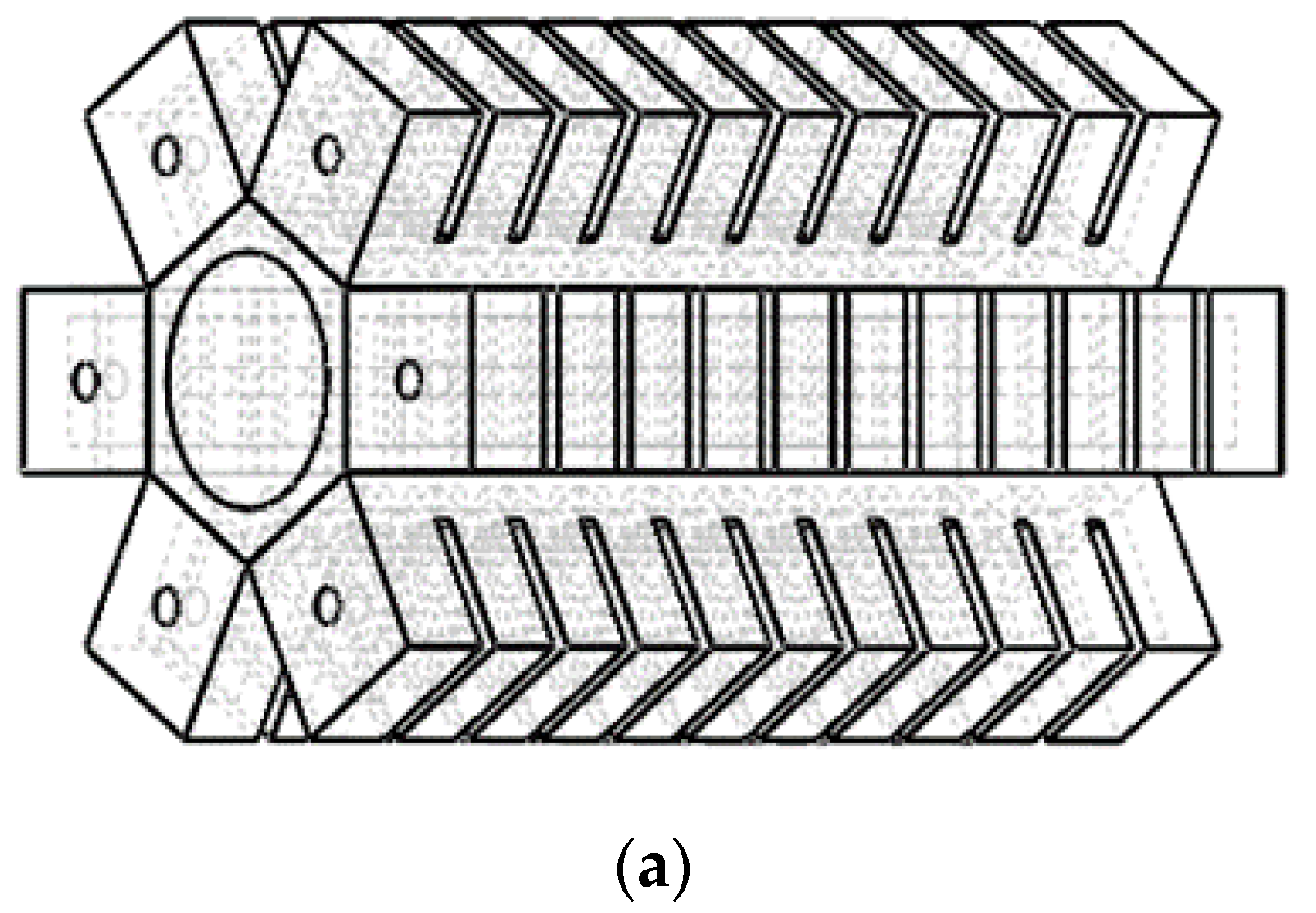
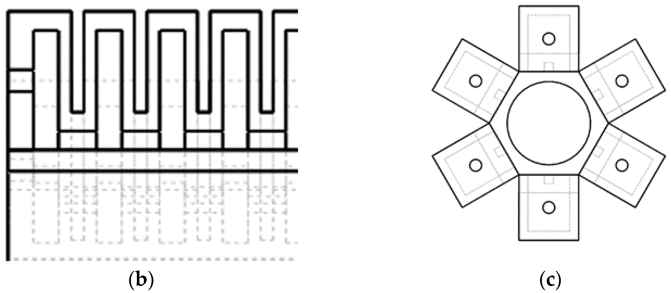
2. Structural Design and Deformation Analysis of Hexagonal Prism Soft-Bodied Bionic Actuator

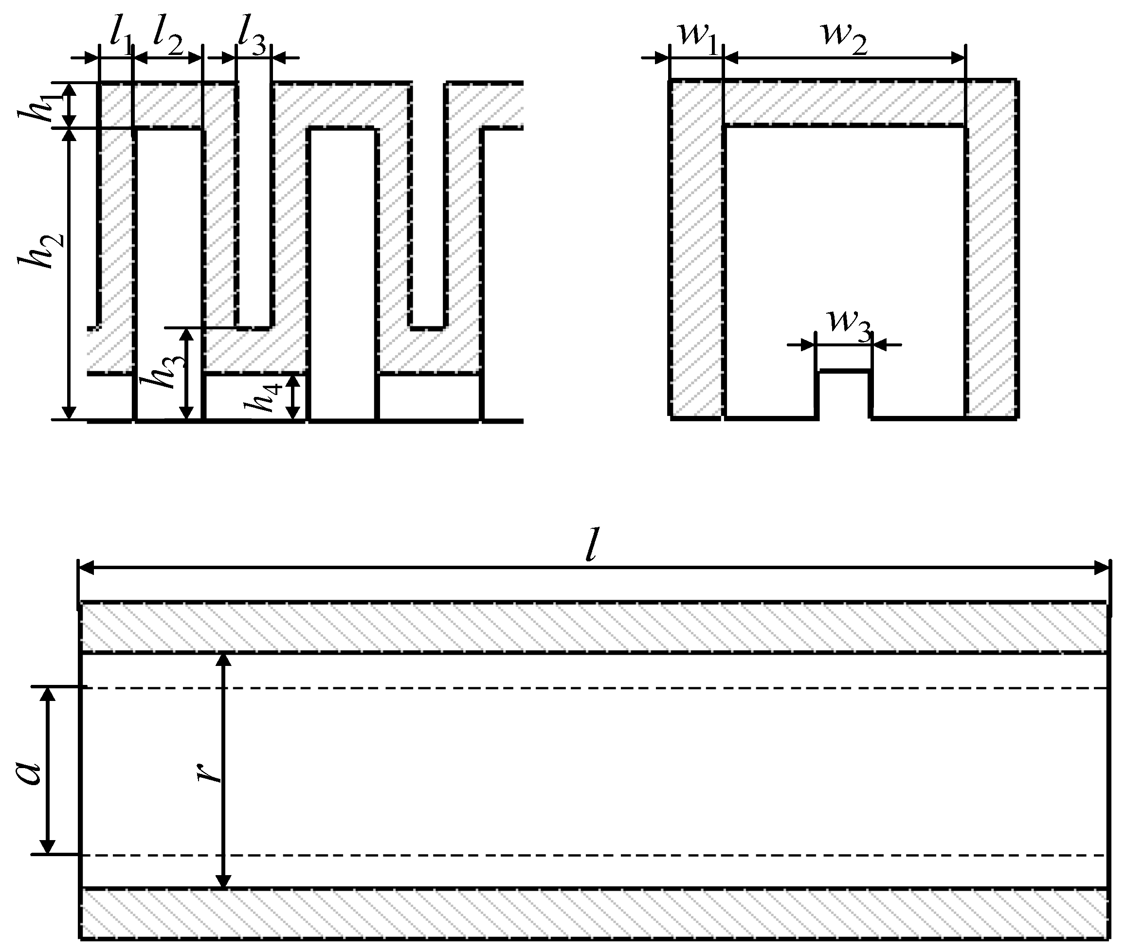
2.1. Principal Design

The movement diagram of the peristaltic soft-bodied pipe robot is shown in Figure 1, and the movement direction of the robot is to the right. By adopting different inflation patterns for the hexagonal prism soft-bodied bionic actuator, radial expansion deformation or axial bending deformation can be produced respectively: when facing a pipe with a running pipe diameter similar to the size of the hexagonal prism soft-bodied bionic actuator, the actuator can adopt the radial expansion deformation mode, and the robot can move in the pipe in a manner similar to earthworm peristalsis (Figure 1a); when the size of the pipe is much larger than that of the hexagonal prism soft-bodied bionic actuator, the actuator can adopt the axial bending deformation mode, and the robot adopts the flexion and extension motion similar to inchworm larva in the pipe (Figure 1b).
The structure of the hexagonal prism soft-bodied bionic actuator is shown in Figure 2; the main components are six basic rectangular cavities with the same structural size and one non-retractable regular hexagonal silicone rubber column. The rectangular bottom surfaces of the six rectangular cavities are respectively bonded with the six rectangular sides of the regular hexagonal silicone rubber column through silicone rubber adhesion technology. Each rectangular cavity is composed of 11 air cavity structures. In addition, in order to enhance the movement ability and reduce the weight of the actuator, and consider the integration of power source and control system, the regular hexagonal silicone rubber column adopts a circular hollow structure.
The main structural parameters of the hexagonal prism soft-bodied bionic actuator are shown in Table 1. The design requires that the wall thickness of the expansion wall of the air cavity structure is less than the other wall thickness, so as to ensure that the deformation of the actuator is mainly realized by the interaction between the expansion walls.

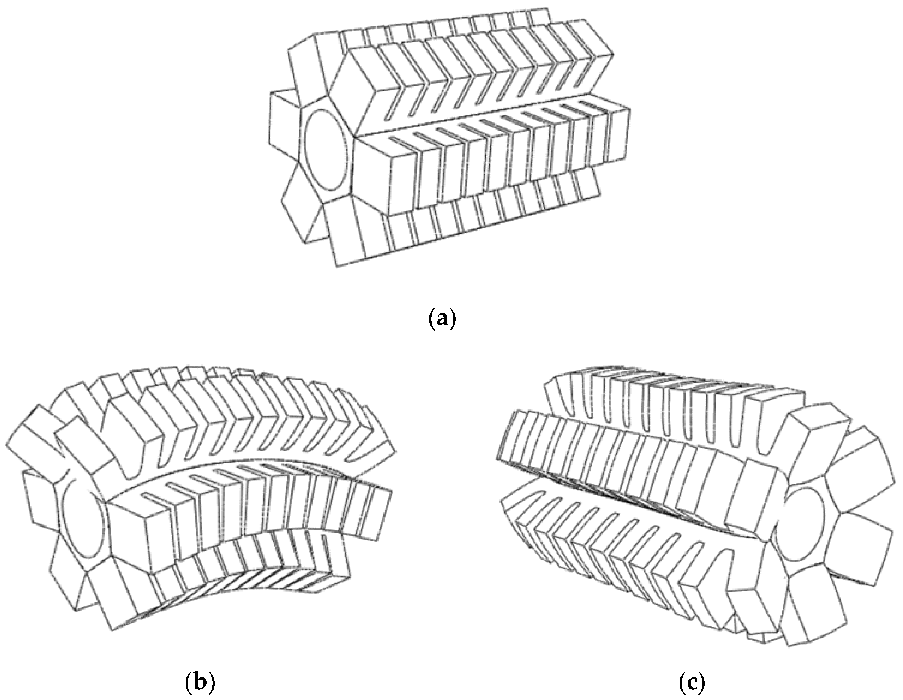
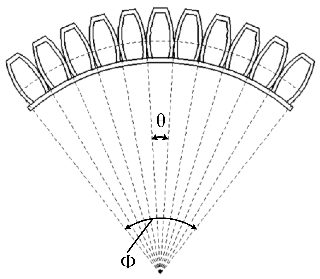
2.2. Deformation Mode Analysis

The hexagonal prism soft-bodied bionic actuator can produce axial bending deformation and radial expansion deformation by different inflation patterns. The principle is as follows: when six rectangular cavities are filled with gases at different pressures, the deformation degree of each rectangular cavity is different, and the driver will bend towards the side with a small deformation degree of the rectangular cavity, allowing the soft-bodied actuator to realize axial bending deformation; when the same air pressure is applied to all six rectangular cavities at the same time, the deformation degree of each cavity is the same, the actuator will not bend, but will increase the overall radial size and realize radial expansion and deformation. According to the requirement of ensuring the stable movement of the robot in the pipeline in reference [30], this paper only analyzes the bending deformation of the hexagonal prism soft-bodied bionic actuator with two cavities inflated. The inflation deformation diagram of hexagonal prism soft-bodied bionic actuator is shown in Figure 3.

3. Mechanical Model Analysis

3.1. Constitutive Model of Silicone Rubber

The soft-bodied actuator is made of silicone, which is a material with non-linear, superelastic, and large deformation, and shows almost no change in volume (that is, it is incompressible). Its mechanical properties are usually expressed and analyzed by the strain energy density function. The most commonly used strain potential energy models include the Mooney–Rivlin model, Yeoh model, and Ogden model [31,32,33,34,35,36]. According to the literature, the Yeoh model can fit other different deformation modes according to the data of the uniaxial tensile test, such as uniaxial compression and shear, and is suitable for simulating large deformation. It is the preferred constitutive model for analyzing the deformation of silicone rubber.
For isotropic silicone rubber materials, based on the stress–strain relationship, the constitutive relationship of silicone rubber materials can be expressed by the strain energy density function:
{ W = W ( I 1 , I 2 , I 3 ) I 1 = λ 1 2 + λ 2 2 + λ 3 2 I 2 = λ 1 2 λ 2 2 + λ 2 2 λ 3 2 + λ 1 2 λ 3 2 I 3 = λ 1 2 λ 2 2 λ 3 2
where I 1 , I 2 and I 3 are deformation tensor invariants, and λ 1 , λ 2 and λ 3   are   the   main   elongation   ratios .   For   incompressible   silicone   rubber   materials :   I 3 = λ 1 2 λ 2 2 λ 3 2 = 1 .
Assuming that the material does not deform in the width direction, then λ 3 = 1 , we can get:
λ 1 = 1 λ 2
I 1 = I 2 = λ 1 2 + 1 λ 1 2 + 1
The strain energy density function of the typical second-order Yeoh constitutive model is as follows:
W = C 10 ( I 1 3 ) + C 20 ( I 1 3 ) 2 = C 10 ( λ 1 1 λ 1 ) 2 + C 20 ( λ 1 1 λ 1 ) 4
According to reference [37], the material coefficient in the formula C 10 = 0.11 , C 20 = 0.02 .

3.2. Establishment of the Mechanical Model of Hexagonal Prism Soft-Bodied Bionic Actuator

The hexagonal prism soft-bodied bionic actuator can realize axial bending deformation and radial expansion deformation respectively by using different inflation patterns. This section only establishes the mathematical model of the actuator bending deformation, and the radial expansion deformation of the actuator is only verified by simulation and experiment later in the paper. By simplifying the model, the overall bending angle of the actuator can be regarded as the result of the superposition of the bending angles of each airbag in a single rectangular cavity. The equivalent diagram of actuator bending deformation is shown in Figure 4. Wherein, the overall bending angle of the actuator is represented by Φ , the bending angle of a single airbag is represented by θ , and the number of airbags is represented by N , then θ = Φ N = Φ 11 .
The structural parameters of hexagonal prism soft-bodied bionic actuator are shown in Figure 5, where l 1 is the thickness of airbag expansion wall, l 2 , w 2 and h 2 are the length, width, and height of airbag respectively, h 1 and w 1 are the thickness of airbag top wall and sidewall respectively, h 4 and w 3 are the width and height of cavity airway. l is the length of a regular hexagonal prism, a is side length, and r is the radius of a hollow cylinder.
In order to simplify the analysis, the following assumptions are put forward for the modeling process of hexagonal prism soft-bodied bionic actuator:
The total volume of silicone rubber does not change before and after deformation;
The mechanical effect of the rectangular cavity on the passive deformation side of the hexagonal prism soft-bodied bionic actuator on the overall deformation process is not considered;
The curvature of the hexagonal prism soft-bodied bionic actuator changes uniformly in the process of bending deformation.
Based on the above assumptions, when other external forces are ignored and the bending deformation of the hexagonal prism soft-bodied bionic actuator reaches a stable state, the work done by the driving air pressure is completely used to overcome the internal stress of the silicone rubber material. According to the principle of virtual work, the following balance equation can be established:
P d V A = V R d W
where P is the driving air pressure, V A is the volume of the air chamber, and V R is the volume of silicone rubber material. Where V R can be calculated by the following formula:
V R = 2 V a + V b
where V a is the volume of silicone rubber material in a single rectangular cavity, and V b is the volume of a hollow hexagonal prism. From Figure 4:
V a = N ( L a W a H a l 2 w 2 h 2 ) + l 3 h 3 W a ( N 1 ) V b = ( 3 3 2 a 2 π r 2 ) l
where:
L a = 2 l 1 + l 2 W a = 2 w 1 + w 2 H a = h 1 + h 2
The volume V 0 of a single rectangular cavity before deformation is:
V 0 = N L a W a H a + l 3 h 3 w 3 ( N 1 )
The volume of the air chamber of the deformed rectangular cavity is V A = 2 ( V 1 V a ) , and V 1 is the volume of a single rectangular cavity after deformation, which can be approximately calculated as follows:
V A = 2 ( ( 1 + λ 1 ) V 0 V a )
The main elongation ratio of the rectangular cavity is:
λ 1 = Φ sin Φ
Based on the above analysis process, the relationship between the bending angle Φ of the soft-bodied actuator and the driving air pressure P is obtained as follows:
P = ( sin Φ ) 2 V R 2 V 0 ( sin Φ Φ cos Φ ) d W d Φ
Finally, the P Φ curve of the theoretical deformation model of the soft-bodied actor is obtained, as shown in Figure 6. It can be seen that the input pressure of the actuator is approximately linear with the output angle.

4. Verification of Numerical Simulation Algorithm and Preparation of Physical Model

4.1. Numerical Simulation Algorithm Verification

Considering the requirements of the motion mode of the peristaltic soft-bodied pipe robot on the deformation function of the actuator, the rationality of the structure and function of the hexagonal prism soft-bodied bionic actuator is verified by using the numerical simulation algorithm, and the accuracy of its deformation analysis theoretical model is tested [38,39,40,41].
Because the actuator is made of a hyperelastic material, its material characteristics have a nonlinear relationship. Compared with other simulation software, ABAQUS simulation software has great advantages in solving various nonlinear problems. Therefore, this simulation software is used to simulate and analyze the software driver. When ABAQUS is used, ABAQUS/standard is used for simulation analysis. The main steps in the simulation process are:
(1)
Model establishment
The structure of each part of the soft actuator is established by using three-dimensional software, and imported into ABAQUS software to impose constraints for assembly.
(2)
Soft-bodied actuator material and load setting
Since silicone rubber is a hyperelastic material, when defining the material characteristics, in addition to defining the density of the material, it is also necessary to set its hyperelasticity in the hyperelastics option, in which the strain energy function is Yeoh type, the silicone rubber model parameter is C 10 = 0.11 , C 20 = 0.02 , and the density is ρ = 1130   kg / m 3 .
When applying a load, first create a plane in the surface where the load is to be applied. Secondly, the load application is realized by creating the analysis step and setting the loads in the analysis step.
(3)
Soft-bodied actuator meshing
When dividing the mesh, the method of dividing the model is adopted, and the hexahedron is used to sweep the mesh. When setting the mesh, because the silica gel is incompressible and has the characteristics of large deformation under stress, the mesh is set as a secondary hybrid solid element (C3D10H).
(4)
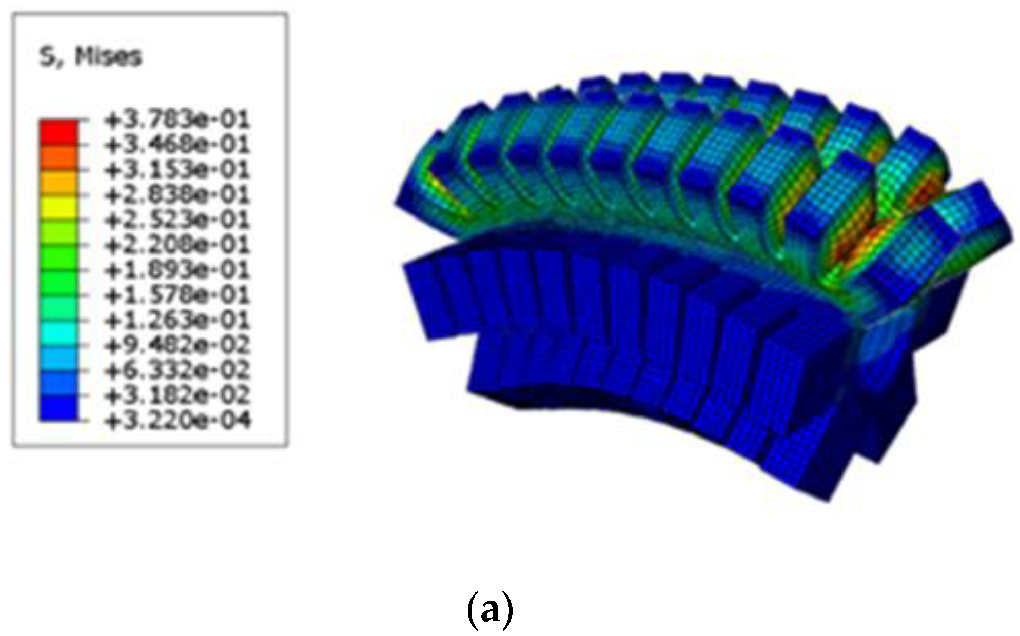
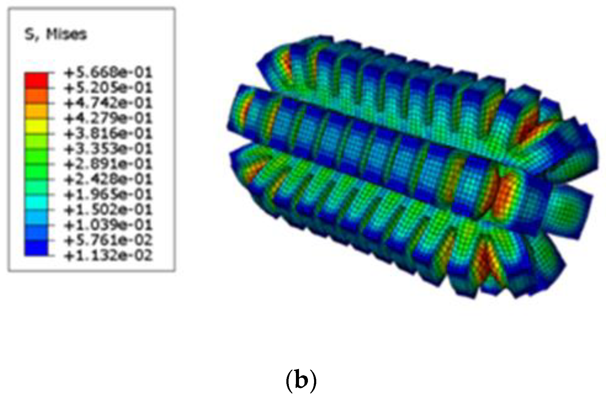
Create a working file and conduct simulation analysis to obtain the deformation analysis diagram of hexagonal prism soft-bodied actuator, as shown in Figure 7.
According to Figure 7, the deformation of the hexagonal prism soft-bodied bionic actuator can meet the needs of the peristaltic soft-bodied pipe robot to realize multiple motion modes, and the deformation change law of the cloud diagram conforms to the actual deformation of the silicone rubber material after ventilation, which can verify the rationality of the structure and function of the actuator. Through numerical simulation calculation, the bending angle of the actuator under different driving pressures from 40 kPa to 280 kPa is obtained, as shown in Table 2.
The calculation results in Table 2 are compared with the theoretical model of driver bending deformation, as shown in Figure 8.
According to Figure 8, when the driving pressure is not greater than 200 kPa, the calculation result curve of the numerical simulation algorithm approximately coincides with the curve of the theoretical model, which can prove that the theoretical model of deformation analysis has a certain accuracy. The driving pressure continues to increase, and the error between the two curves becomes larger. After analysis, this was found to be because the influence of the rectangular cavity on the passive deformation side of the hexagonal prism soft-bodied bionic actuator on the bending deformation is not considered in the theoretical model analysis.

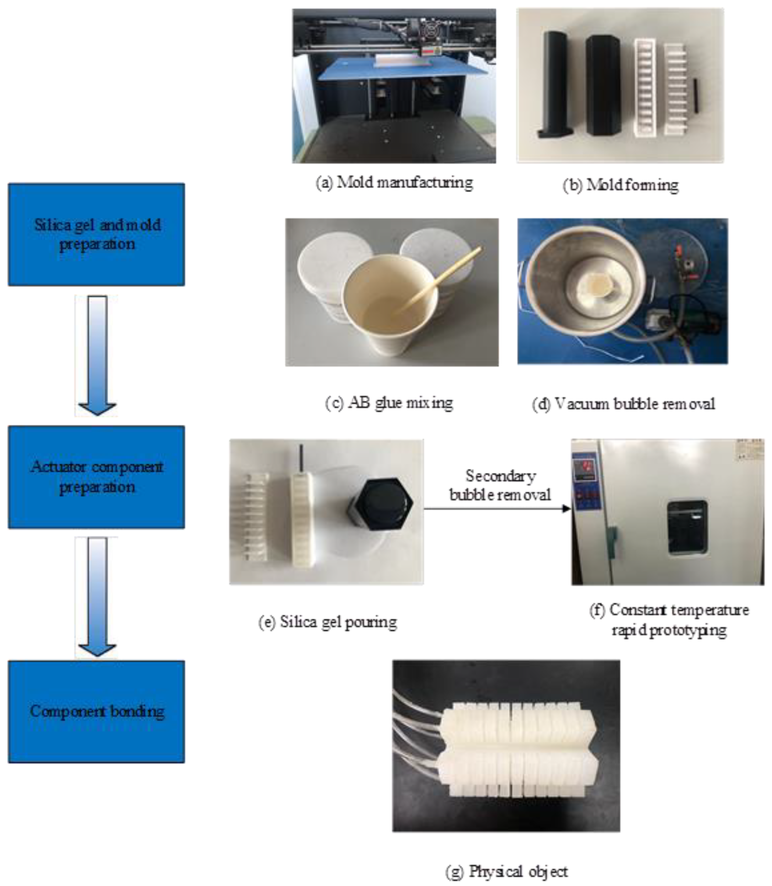
4.2. Physical Model Preparation

At present, there are two main manufacturing methods for pneumatic soft-bodied actuators: mold pouring type and 3D printing type [42]. Among them, 3D printing silicone products can only produce products with a relatively simple structure, and the cost is high. Therefore, this paper uses the mold pouring method to make the hexagonal prism soft-bodied bionic actuator. The materials required for the preparation method are shown in Table 3.
The physical model preparation process of the hexagonal prism soft-bodied bionic actuator is shown in Figure 9. Firstly, the cavity mold must be designed, and then printed by 3D printer; then, mix the platinum silicone rubber of components A and B to a ratio of 1:1, and the stock solution is obtained after uniform stirring; place the stock solution in a vacuum environment to remove bubbles, then pour the stock solution into the prepared mold, and remove bubbles for a second time. After removing bubbles, put the mold containing the stock solution into a 60 °C incubator and stand for 2 h. After curing and forming, demould to obtain the mold cavity; finally, the silicon rubber adhesive is used to bond each part of the cavity in order to obtain the hexagonal prism soft-bodied bionic actuator.
In view of the dual requirements of a pipeline and soft-bodied robot, it is necessary to ensure that the prepared actuators not only have flexibility, but also have a certain strength and wear resistance. Through a large number of data analyses and experimental tests, Shore A45 platinum silicone rubber was chosen as the preparation material for the hexagonal prism soft-bodied bionic actuator.

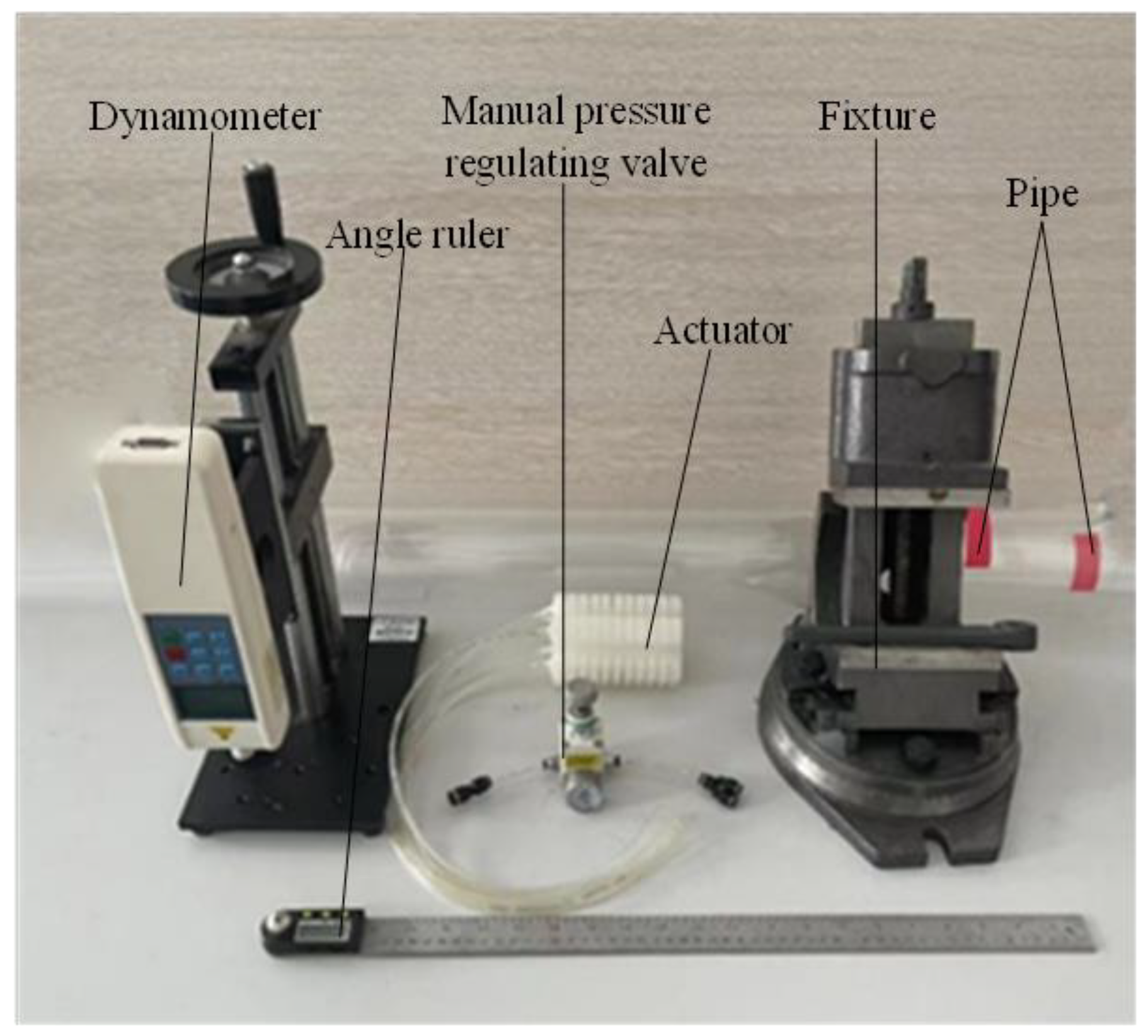
5. Experimental Test and Analysis of Hexagonal Prism Soft-Bodied Bionic Actuator

Through experimental test and analysis, we verified the different deformation effects of the hexagonal prism soft-bodied bionic actuator in the pipeline, and explored the influence of driving pressure on the motion and dynamic characteristics of the actuator, which can lay a foundation for the further optimal application of the actuator. The experimental device is shown in Figure 10. It mainly includes a hexagonal prism soft-bodied bionic actuator, air pump, manual pressure regulating valve, angle ruler, electronic dynamometer, fixture, and acrylic tubes with different pipe diameters.
Different inflation strategies were adopted for the hexagonal prism soft-bodied bionic actuator in a pipeline with inner diameter of 84 mm and 115 mm respectively, and the deformation diagram of the actuator as shown in Figure 11 was obtained.
It can be seen from Figure 11 that the deformation mode of the hexagonal prism soft-bodied bionic actuator can meet the functional requirements of the multi-motion mode soft-bodied pipe robot, and the inflation strategy of double cavity inflation is adopted to give the actuator stability in the pipe.

5.1. Experimental Analysis of Axial Bending Deformation of Hexagonal Prism Soft-Bodied Bionic Actuator

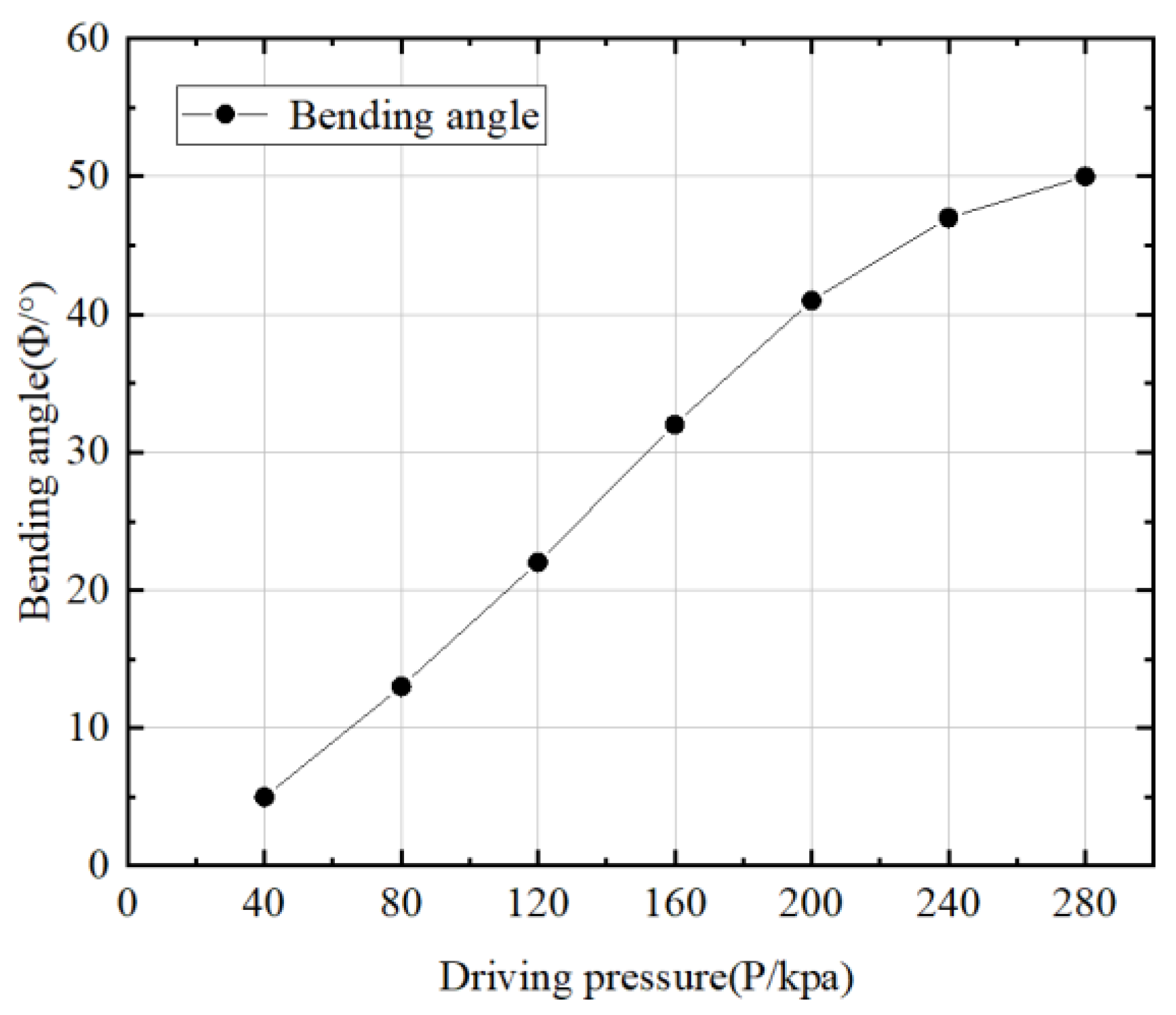
5.1.1. Analysis of Motion Characteristics of Hexagonal Prism Soft-Bodied Bionic Actuator

The soft-bodied actuator is preset with different driving pressures through the pressure regulating valve, so that the hexagonal prism soft-bodied bionic actuator has different degrees of bending deformation, and then the digital display angle ruler is used to collect the bending angle data. Finally, the P Φ characteristic curve of the driving pressure and bending angle of the actuator can be obtained, as shown in Figure 12.
It can be seen from Figure 12 that the bending angle range of the hexagonal prism soft-bodied bionic actuator is 0 50 ° . Among them, the change of P Φ characteristic curve shows a certain linear relationship, but when the driving air pressure exceeds 200 kPa, it shows a non-linear change trend, because when the driving air pressure reaches 200 kPa, each air cavity of the rectangular cavity on the bent side begins to contact. When the pressure continues to increase, the interaction between the air cavities increases the counter bending moment of the actuator, hindering the effect of bending deformation. This can also explain the reason for the error between the simulation results and the theoretical model when the driving pressure is greater than 200 kPa.
According to the P Φ characteristic curve, the empirical formula reflecting the characteristic change can be obtained, and its expression is:
f ( x ) = p 1 · x 4 + p 2 · x 3 + p 3 · x 2 + p 4 · x + p 5
The specific coefficients in the formula are shown in Table 4.
Error analysis was performed on the characteristic curve of P Φ obtained from the experimental test, the calculation result of the numerical simulation algorithm and the theoretical model, as shown in Figure 13.
It can be seen from Figure 13 that the coincidence degree between the simulation curve and the experimental curve is high, which can prove that the numerical simulation calculation method is correct, and the theoretical model of deformation analysis is also accurate when the driving pressure is not greater than 200 kPa.

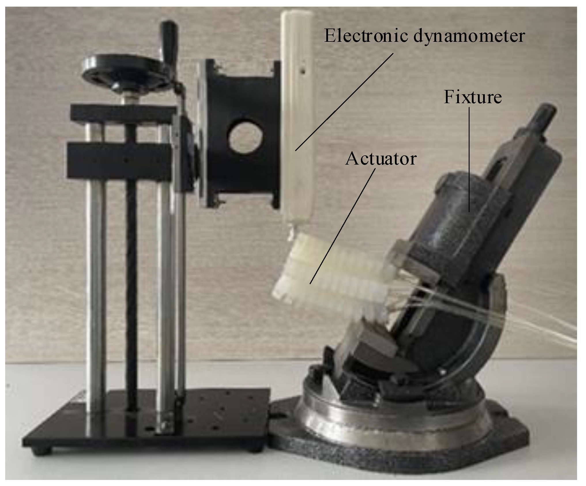
5.1.2. Dynamic Characteristics Analysis of Hexagonal Prism Soft-Bodied Bionic Actuator

The driving torque generated by the bending deformation of the hexagonal prism soft-bodied bionic actuator is collected by the electronic dynamometer, as shown in Figure 14.
The P M characteristic curve of driving pressure and driving moment is shown in Figure 15. It can be seen from the figure that with the increase in driving pressure, the output moment of the actuator also increases. Conversely, when the rectangular cavity on the bent side begins to contact, the increase range of output moment begins to decrease with the increase in driving pressure.
For the designed soft-bodied pipe robot, the larger the bending angle and output moment of the hexagonal prism soft-bodied bionic actuator the worse, as the contact area between the actuator and the pipe decreases with the increase in bending angle. However, in the experiment, it is found that when the driving pressure is 80 kPa, the contact area between the actuator and the pipeline reaches the minimum value. With the increase in the driving pressure, the contact area does not change, but the output moment will continue to increase, and then the friction between the actuator and the pipeline will increase, and the high driving pressure will reduce the service life of the actuator and increase the maintenance cost. Therefore, 80 kPa can be set as the driving pressure of the axial bending deformation mode of the hexagonal prism soft-bodied bionic actuator.
The P M characteristic curve is expressed by empirical Formula (13), and its specific coefficients are shown in Table 5.

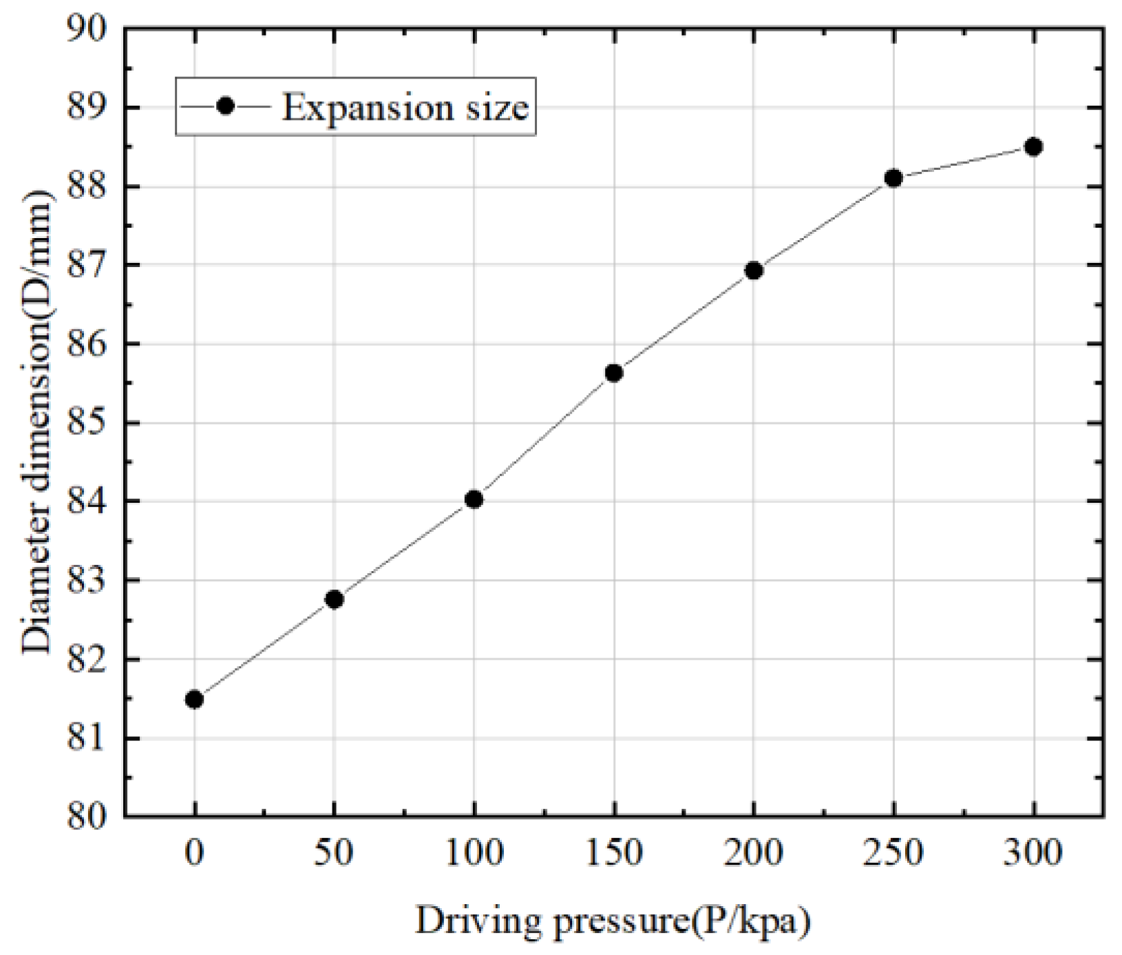
5.2. Experimental Analysis of Radial Expansion Deformation of Hexagonal Prism Soft-Bodied Bionic Actuator

Taking the maximum circumscribed circle diameter of the hexagonal prism soft-bodied bionic actuator as the measurement size, the radial expansion deformation of the hexagonal prism soft-bodied bionic actuator occurs to varying degrees by changing the size of the air pressure introduced into the hexagonal prism soft-bodied bionic actuator, and the data is collected to obtain the characteristic curves of the driving pressure and the expansion dimension P D , as shown in Figure 16.
It is known that the diameter of the selected experimental pipe is 84 mm. It can be seen from Figure 16 that when the driving pressure is 150 kPa, the diameter of the actuator becomes 84 mm. When the pressure continues to increase, the actuator will be fixed in the pipe. The greater the driving pressure, the better the fixing effect, but too much driving pressure is not the better, as overly high pressure will cause irreversible damage to the actuator. According to the motion requirements of the peristaltic soft-bodied pipe crawling robot, the minimum driving pressure of the drive at different inclination angles of the pipe is obtained through experiments, as shown in Table 6. With the increase in inclination angle, the driving pressure required to fix the actuator is greater.

6. Conclusions

According to the requirements of multi-motion modes for peristaltic prism soft-bodied pipe robots, a hexagonal prism soft-bodied bionic actuator is designed. By using different inflation strategies, the actuator can achieve different deformations.
(1)
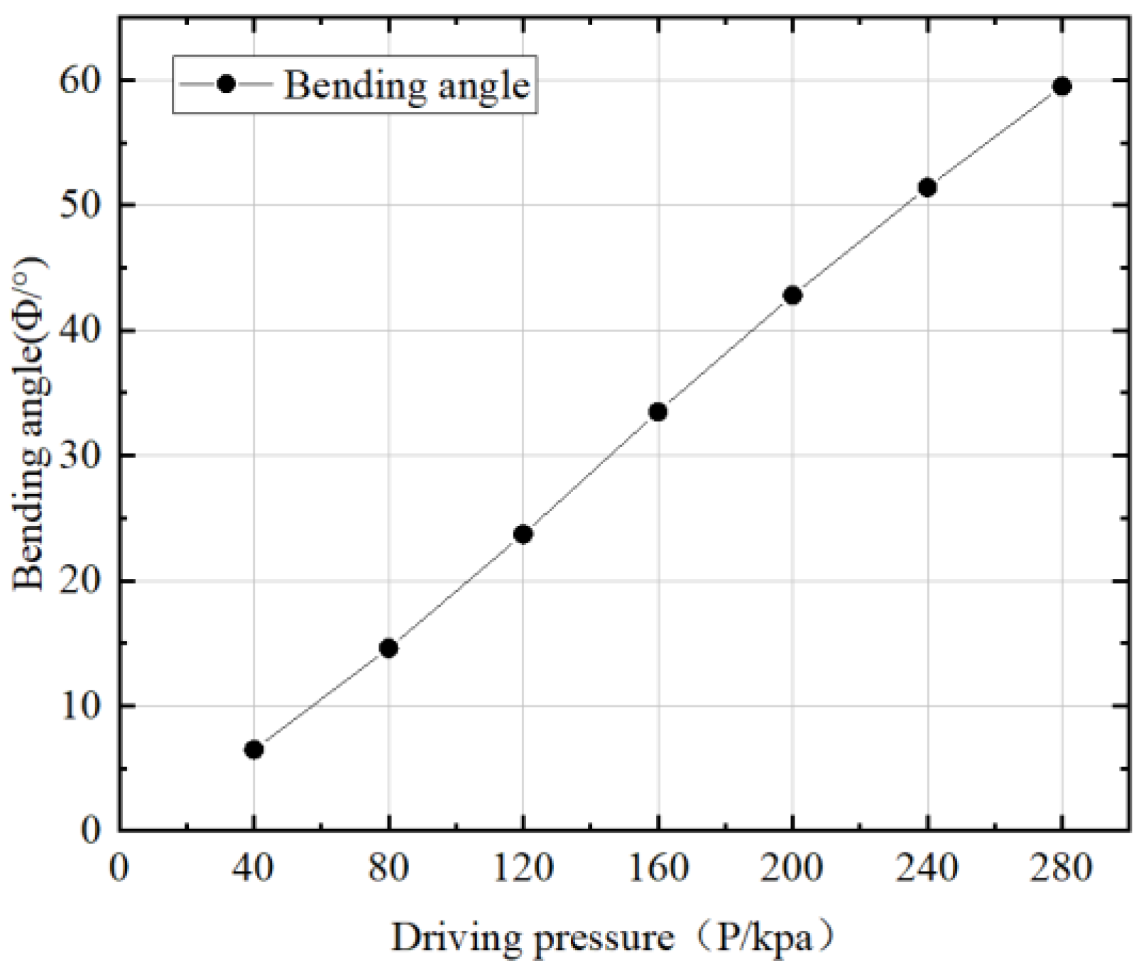
Based on the Yeoh binomial parameter silicone constitutive model, a deformation analysis model of the actuator is established to obtain the relationship between the bending angle of the actuator and the driving pressure, which can provide a theoretical reference for the structural design and deformation analysis of the soft-bodied actuator.
(2)
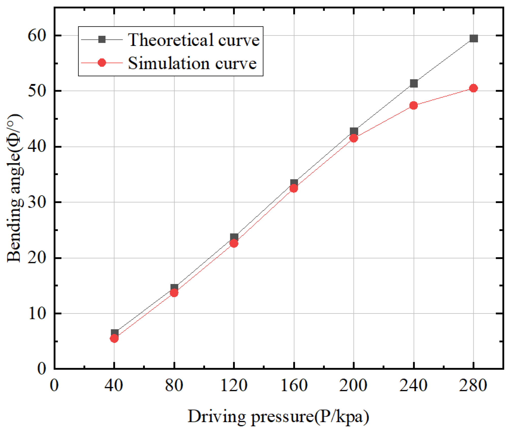
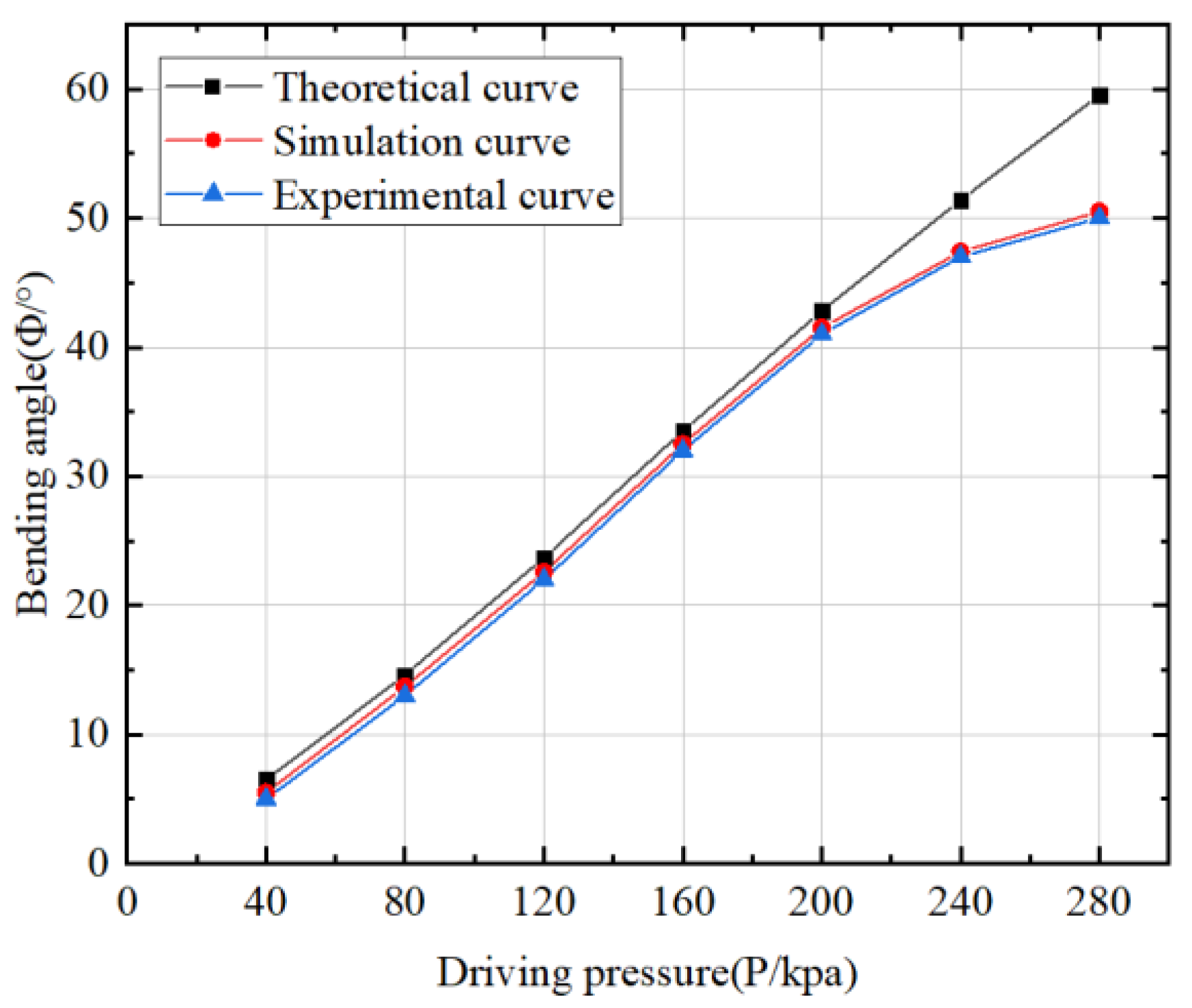
Using numerical simulation technology, the rationality of the structure and function of the actuator is verified. When the driving pressure is not more than 200 kPa, the comparison error between the numerical simulation results and the theoretical model is 7.18%, which verifies that the deformation analysis model has a certain accuracy.
(3)
An experimental platform is built to verify and analyze the performance of the prepared actuator. According to the input driving air pressure value, matching a certain range of motion and power output, the characteristic curves of actuator bending angle and driving moment are obtained, and the empirical formula is fitted. The accuracy of the deformation analysis model and numerical simulation algorithm is verified, and the radial expansion deformation characteristics of the actuator are experimentally studied. Finally, it is determined that the actuator is reasonable and feasible, and can be used as the driving mechanism of a multi-motion mode soft-bodied pipe crawling robot.

Author Contributions

Conceptualization, N.W. and Y.Z.; methodology, N.W. and G.Z.; software, N.W. and L.P.; validation, N.W. and W.Z.; formal analysis, N.W. and Y.Z.; investigation, N.W.; resources, Y.Z. and W.Z.; data curation, N.W. and L.P.; writing—original draft preparation, N.W.; visualization, N.W. and W.Z.; supervision, Y.Z.; project administration, N.W. and Y.Z.; funding acquisition, Y.Z.; All authors have read and agreed to the published version of the manuscript.

Funding

This work was supported by the National Natural Science Foundation of China (General Program) [grant number 52005344].

Data Availability Statement

All data generated or analyzed during this study are included in this article.

Conflicts of Interest

The authors declare that there is no conflict of interest regarding the publication of this paper.

References

  1. Abidin, A.S.Z.; Zaini, M.H.; Pauzi, M.F.A.M.; Sadini, M.M.; Chie, S.C.; Mohammadan, S.; Jamali, A.; Muslimen, R.; Ashari, M.F.; Jamaludin, M.S.; et al. Development of Cleaning Device for In-pipe Robot Application. Procedia Comput. Sci. 2015, 76, 506–511. [Google Scholar] [CrossRef] [Green Version]
  2. Singh, P.; Ananthasuresh, G.K. A Compact and Compliant External Pipe-Crawling Robot. IEEE Trans. Robot. 2012, 29, 251–260. [Google Scholar] [CrossRef]
  3. Alnaimi, F.B.I.; Mazraeh, A.A.; Sahari, K.S.M.; Weria, K.; Moslem, Y. Design of a multi-diameter in-line cleaning and fault detection pipe pigging device. In Proceedings of the 2015 IEEE International Symposium on Robotics and Intelligent Sensors (IRIS), Langkawi, Malaysia, 18–20 October 2015; pp. 258–265. [Google Scholar]
  4. Patricio, R.A.C.; Baptista, R.M.; Rachid, F.B.D.F.; Bodstein, G.C. Numerical simulation of pig motion in gas and liquid pipelines using the Flux-Corrected Transport method. J. Pet. Sci. Eng. 2020, 189, 106970. [Google Scholar] [CrossRef]
  5. Kim, Y.-G.; Shin, D.-H.; Moon, J.-I.; An, J. Design and implementation of an optimal in-pipe navigation mechanism for a steel pipe cleaning robot. In Proceedings of the 2011 8th International Conference on Ubiquitous Robots and Ambient Intelligence (URAI), Incheon, Korea, 23–26 November 2011; pp. 772–773. [Google Scholar]
  6. Oya, T.; Okada, T. Development of a steerable, wheel-type, in-pipe robot and its path planning. Adv. Robot. 2005, 19, 635–650. [Google Scholar] [CrossRef]
  7. Dewei, T.; Qingkai, L.; Shengyuan, J.; Deng, Z. Analysis of differential characteristics and drag force of three-axis differential pipeline robot when passing through elbow. Robot 2010, 32, 91–96. [Google Scholar]
  8. Gunatilake, A.; Piyathilaka, L.; Kodagoda, S.; Barclay, S.; Vitanage, D. Real-Time 3D Profiling with RGB-D Mapping in Pipelines Using Stereo Camera Vision and Structured IR Laser Ring. In Proceedings of the 2019 14th IEEE Conference on Industrial Electronics and Applications, Xi’an, China, 19–21 June 2019; pp. 916–921. [Google Scholar]
  9. Zhang, L.; Wang, X. Stable motion analysis and verification of a radial adjustable pipeline robot. In Proceedings of the 2016 IEEE International Conference on Robotics and Biomimetics (ROBIO), Qingdao, China, 3–7 December 2016; pp. 1023–1028. [Google Scholar]
  10. Chen, X.; Wu, Z.; He, S.; Xiao, X. Trafficability design of adaptive supporting pipeline inspection robot. J. Cent. South Univ. (Nat. Sci. Ed.) 2018, 49, 2953–2962. [Google Scholar]
  11. Matuliauskas, A.; Spruogis, B.; Pikūnas, A. Wall Press Walking In-Pipe Robot. Solid State Phenom. 2006, 113, 296–300. [Google Scholar] [CrossRef]
  12. Yu, X.; Chen, Y.; Chen, M.Z.Q.; Lam, J. Development of a Novel In-Pipe Walking Robot. In Proceedings of the 2015 IEEE International Conference on Information and Automation, Lijiang, China, 8–10 August 2015; pp. 364–368. [Google Scholar]
  13. Savin, S. Parameter Optimization for Walking Patterns and the Geometry of in-Pipe Robots. In Proceedings of the 2018 International Conference on Industrial Engineering, Applications and Manufacturing (ICIEAM), Moscow, Russia, 15–18 May 2018. [Google Scholar]
  14. Qiao, J.; Shang, J.; Chen, X. Development of an Inchworm In-pipe Robot Based on the Cam Self-locked Principle. J. Mech. Eng. 2010, 46, 83–88. [Google Scholar] [CrossRef]
  15. Ishikawa, R.; Tomita, T.; Yamada, Y.; Nakamura, T. Development of the Attachment for the Cable of Peristaltic Crawling Robot to Reduce Friction in Elbow Pipe. In Intelligent Robotics and Applications. ICIRA 2016. Lecture Notes in Computer Science; Part I; Kubota, N., Kiguchi, K., Liu, H., Obo, T., Eds.; Springer: Berlin/Heidelberg, Germany, 2016; pp. 589–595. [Google Scholar]
  16. Kamata, M.; Yamazaki, S.; Tanise, Y.; Yamada, Y.; Nakamura, T. Morphological change in peristaltic crawling motion of a narrow pipe inspection robot inspired by earthworm’s locomotion. Adv. Robot. 2018, 32, 386–397. [Google Scholar] [CrossRef]
  17. Tao, R.; Chen, Y.; Qingyou, L. A helical drive in-pipe robot based on compound planetary gearing. Adv. Robot. 2014, 28, 1165–1175. [Google Scholar] [CrossRef]
  18. Liu, Q.; Li, Y.; Ren, T.; Chen, Y. Active screw driven pipeline robot. Robot 2014, 36, 711–718. [Google Scholar]
  19. Zhang, Z.; Wang, X.; Wang, S.; Meng, D.; Liang, B. Design and Modeling of a Parallel-Pipe-Crawling Pneumatic Soft Robot. IEEE Access 2019, 7, 134301–134317. [Google Scholar] [CrossRef]
  20. Kellaris, N.; Venkata, V.G.; Smith, G.M.; Mitchell, S.K.; Keplinger, C. Peano-HASEL actuators: Muscle-mimetic, electrohydraulic transducers that linearly contract on activation. Sci. Robot. 2018, 3, eaar3276. [Google Scholar] [CrossRef] [PubMed] [Green Version]
  21. Mao, Z.; Iizuka, T.; Maeda, S. Bidirectional electrohydrodynamic pump with high symmetrical performance and its application to a tube actuator. Sens. Actuators A Phys. 2021, 332, 113168. [Google Scholar] [CrossRef]
  22. Calderon, A.A.; Ugalde, J.C.; Zagal, J.C.; Perez-Arancibia, N.O. Design, fabrication and control of a multi-material-multi-actuator soft robot inspired by burrowing worms. In Proceedings of the 2016 IEEE International Conference on Robotics and Biomimetics (ROBIO), Qingdao, China, 3–7 December 2016; pp. 31–38. [Google Scholar]
  23. Connolly, F.; Polygerinos, P.; Walsh, C.J.; Bertoldi, K. Mechanical Programming of Soft Actuators by Varying Fiber Angle. Soft Robot. 2015, 2, 26–32. [Google Scholar] [CrossRef] [Green Version]
  24. Yamazaki, S.; Tanise, Y.; Yamada, Y.; Nakamura, T. Development of axial extension actuator for narrow pipe inspection endoscopic robot. In Proceedings of the 2016 IEEE/SICE International Symposium on System Integration (SII), Sapporo, Japan, 13–15 December 2016; pp. 634–639. [Google Scholar]
  25. Verma, M.; Ainla, A.; Yang, D.; Harburg, D.; Whitesides, G.M. A Soft Tube-Climbing Robot. Soft Robot. 2018, 5, 133–1377. [Google Scholar] [CrossRef]
  26. Heung, H.; Chiu, P.W.; Li, Z. Design and prototyping of a soft earthworm-like robot targeted for GI tract inspection. In Proceedings of the 2016 IEEE International Conference on Robotics and Biomimetics (ROBIO), Qingdao, China, 3–7 December 2016; pp. 497–502. [Google Scholar]
  27. Liang, J.; Wu, Y.; Yim, J.K.; Chen, H.; Miao, Z.; Liu, H.; Liu, Y.; Liu, Y.; Wang, D.; Qiu, W.; et al. Electrostatic footpads enable agile insect-scale soft robots with trajectory control. Sci. Robot. 2021, 6, eabe7906. [Google Scholar] [CrossRef]
  28. Fan, X.; Dai, N.; Wang, H. Prediction method of bending deformation of pneumatic mesh soft actuator. China Mech. Eng. 2020, 31, 1108–1114. [Google Scholar]
  29. Jiang, C. Design and Application of Worm like Pneumatic Pipeline Robot with Fabric Skin. Master’s Thesis, Donghua University, Shanghai, China, 2021. [Google Scholar]
  30. Zhang, Y.; Wang, N.; Zhao, W. Design and test of peristaltic soft pipe robot. Food Mach. 2020, 36, 82–86. [Google Scholar]
  31. Yirmibesoglu, O.D.; Morrow, J.; Walker, S.; Gosrich, W.; Canizares, R.; Kim, H.; Daalkhaijav, U.; Fleming, C.; Branyan, C.; Menguc, Y. Direct 3D Printing of Silicone Elastomer Soft Robots and Their Performance Comparison with Molded Counterparts. In Proceedings of the 2018 IEEE International Conference on Soft Robotics (RoboSoft), Livorno, Italy, 24–28 April 2018; pp. 295–302. [Google Scholar]
  32. Mei, Y.; Stover, B.; Kazerooni, N.A.; Srinivasa, A.; Hajhashemkhani, M.; Hematiyan, M.; Goenezen, S. A comparative study of two constitutive models within an inverse approach to determine the spatial stiffness distribution in soft materials. Int. J. Mech. Sci. 2018, 140, 446–454. [Google Scholar] [CrossRef]
  33. Panda, S.K.; Buist, M.L. A finite nonlinear hyper-viscoelastic model for soft biological tissues. J. Biomech. 2018, 69, 121–128. [Google Scholar] [CrossRef] [PubMed]
  34. Matouš, K.; Geers, M.G.; Kouznetsova, V.; Gillman, A. A review of predictive nonlinear theories for multiscale modeling of heterogeneous materials. J. Comput. Phys. 2017, 330, 192–220. [Google Scholar] [CrossRef] [Green Version]
  35. Chanda, A.; Callaway, C. Tissue Anisotropy Modeling Using Soft Composite Materials. Appl. Bionics Biomech. 2018, 2018, 4838157. [Google Scholar] [CrossRef] [PubMed] [Green Version]
  36. Zhao, W.; Zhang, Y.; Wang, N. Soft Robotics: Research, Challenges, and Prospects. J. Robot. Mechatron. 2021, 33, 45–68. [Google Scholar] [CrossRef]
  37. Wang, H.; Kang, R.; Wang, X.; Dai, J. Design and modeling of soft bending actuator. J. Beijing Univ. Aeronaut. Astronaut. 2017, 43, 1053–1060. [Google Scholar]
  38. Kao, Y.-T.; Zhang, Y.; Wang, J.; Tai, B.L. Bending behaviors of 3D-printed Bi-material structure: Experimental study and finite element analysis. Addit. Manuf. 2017, 16, 197–205. [Google Scholar] [CrossRef]
  39. Xu, Q.; Liu, J.; Qu, L. Dynamic modeling for silicone beams using higher-order ANCF beam elements and experiment investigation. Multibody Syst. Dyn. 2019, 46, 307–328. [Google Scholar] [CrossRef]
  40. Chen, W.-M.; Lee, T.; Lee, P.V.S.; Lee, J.W.; Lee, S.-J. Effects of internal stress concentrations in plantar soft-tissue—A preliminary three-dimensional finite element analysis. Med. Eng. Phys. 2010, 32, 324–331. [Google Scholar] [CrossRef]
  41. Kindo, S.; Vashistha, R.; Raj, S.; Ravishankar, G.P.; Padwale, M.P. Selection and validation of hyperelastic finite element model for analysis of silicone rubber. In Proceedings of the International Conference of Numerical Analysis and Applied Mathematics (ICNAAM), Thessaloniki, Greece, 25–30 September 2017. [Google Scholar]
  42. Launhardt, M.; Ebel, N.; Kondruweit, M.; Weyand, M.; Volk, T.; Drummer, D. Developing a Patient Individualized Flexible Silicone Implant using SLS and Vacuum Die Casting. In Proceedings of the Europe/Africa Regional Dresden Conference of the Polymer-Processing-Society (PPS), Dresden, Germany, 27–29 June 2017. [Google Scholar]
Figure 1. Motion diagram of peristaltic soft-bodied pipe robot. (a) Radial expansion motion. (b) Axial bending motion.
Actuators 11 00125 g001
Figure 2. Structure diagram of hexagonal prism soft-bodied bionic actuator. (a) Overall structure of actuator. (b) Partial view of actuator section. (c) Actuator end view.
Actuators 11 00125 g002aActuators 11 00125 g002b
Figure 3. Deformation diagram of hexagonal prism soft-bodied bionic actuator. (a) Status of actuator not inflation. (b) State of bending deformation. (c) State of expansion deformation.
Actuators 11 00125 g003
Figure 4. Equivalent model diagram of bending deformation of hexagonal prism soft-bodied bionic actuator.
Actuators 11 00125 g004
Figure 5. Schematic diagram of structural dimensions of hexagonal prism soft-bodied bionic actuator.
Actuators 11 00125 g005
Figure 6. Bending angle–driving pressure curve of the hexagonal prism soft-bodied bionic actuator.
Actuators 11 00125 g006
Figure 7. Deformation analysis diagram of hexagonal prism soft-bodied bionic actuator. (a) Bending deformation of hexagonal prism soft-bodied bionic actuator. (b) Expansion deformation of hexagonal prism soft-bodied bionic actuator.
Actuators 11 00125 g007aActuators 11 00125 g007b
Figure 8. Comparison between simulation curve and the theoretical curves.
Actuators 11 00125 g008
Figure 9. Physical preparation process of the hexagonal prism soft-bodied bionic actuator.
Actuators 11 00125 g009
Figure 10. Experimental device diagram.
Actuators 11 00125 g010
Figure 11. Pipe deformation diagram of hexagonal prism soft-bodied bionic actuator. (a) The actuator bends and deforms in the pipe. (b) The actuator expands and deforms in the pipe.
Actuators 11 00125 g011
Figure 12. The characteristic curve of the hexagonal prism soft-bodied bionic actuator.
Actuators 11 00125 g012
Figure 13. Actuator bending deformation error analysis diagram.
Actuators 11 00125 g013
Figure 14. Driving moment measurement of hexagonal prism soft-bodied bionic actuator.
Actuators 11 00125 g014
Figure 15. A characteristic curve of the hexagonal prism soft-bodied bionic actuator.
Actuators 11 00125 g015
Figure 16. A characteristic curve of the hexagonal prism soft-bodied bionic actuator.
Actuators 11 00125 g016
Table 1. Main structural parameters of the actuator.
No.SizeNum
1Height of rectangular cavity h 2 19 mm
2Length of rectangular cavity w 2 14 mm
3Width of rectangular cavity l 2 4 mm
4Thickness of expansion wall of rectangular cavity l 3 2 mm
5Side length of hexagonal silicone rubber column a 20 mm
6Length of hexagonal silicone rubber column l 112 mm
7Dimensions of hollow structure of hexagonal silicone rubber column r 14 mm
8Number of air chamber structures N 11
Table 2. Numerical simulation algorithm calculation results.
Driving pressure ( P / kpa ) 4080120160200240280
Bending angle ( θ / ° ) 5.513.722.632.541.547.450.5
Table 3. Preparation of materials.
Preparation of Required ConsumablesMaterial Details
Rectangular cavityShore A45 platinum silicone rubber
Hexagonal silicone rubber columnShore A45 platinum silicone rubber
Pouring mouldPLA
adhesivesilicone adhesive
Table 4. Empirical formula coefficient of the characteristic curve.
Coefficient p 1 p 2 p 3 p 4 p 5
1.1097 × 10⁻⁸−9.4894 × 10−60.00240.01461.2143
Table 5. Empirical formula coefficient of P M a characteristic curve.
Coefficient p 1 p 2 p 3 p 4 p 5
−1.4254 × 10−71.8295 × 10−50.0163−0.9734107.200
Table 6. Comparison table of pipe inclination and minimum driving pressure.
Tilt Angle (°)0306090
Driving pressure (kPa)160175195225
Publisher’s Note: MDPI stays neutral with regard to jurisdictional claims in published maps and institutional affiliations.

