Abstract
Disturbance from luminance variation in the identification of visual sensors causes instability in the control system of target tracking, which leads to field of vision (FOV) motion and even the target missing. To solve this problem, a linear active disturbance reject controller (LADRC) is adopted to the visual tracking and inertial stable platform (VTISP) for the first time to improve the system’s robustness. As a result, the random disturbance from identification can be smoothed by the tracking differentiator (TD).An improved linear extended state observer (LESO) modified by the TD is provided to obtain the high-order state variables for feedback. That makes the system avoid noise in a differential process from the MEMS gyroscope and enhances the response time and stability in tracking control. Finally, simulation and experimental studies are conducted, and the feasibility of the LADRC is verified. Moreover, compared with the other controller in the VTISP for remote sensing, the superiority of the LADRC in system response time and stability is proved by the experiments.
1. Introduction
Generally, the visual tracking and inertial stabilized platform (VTISP) identifies the target with a visual sensor and maintains the target in the center of the field of vision (FOV) by adjusting the multi axis gimbals, which are controlled by an inertially stabilized system. The disturbance from the base vehicle can be eliminated by maintaining the stabilization of the line of sight (LOS). Hence, the VTISP is applied for remote sensing in robotics, navigation, unmanned vehicles, and industrial equipment, which consists of a visual processing module and the inertial stabilized platform (ISP). Accurate target identification takes an important part in the VTISP control system. However, there are many challenges when the target is under varying environmental illumination conditions, as when clouds obscure the sun or when the light source direction changes, for example [1]. Therefore, the identification in those situations could introduce disturbance into the ISP. Then, the unstable gimbals with a visual sensor create scene motion blur, and the performance of the control system gets worse. High-resolution cameras and high-performance integrated circuits for complex algorithms processing are used to improve the accuracy of object identification. Many particle-filter-based algorithms in computer vision processing and modified machine learning are applied to develop robust object identity results [2,3,4,5,6,7,8]. However, miniaturized vehicles employing visual sensors that are lighter, smaller, and lower cost limit the application of most of the complex algorithms [9,10,11]. In recent years, researchers have placed emphasis on the visual processing orthe control theory of the ISP. However, researchers have seldom considered both as a whole system to research. It is meaningful to study the crossing field so to solve problems in its application. The idea of crossing-field research has been promoted in biocybernetics, such as control systems for the brain–computer interface [12]. In this research, a novel approach is proposed to resolve the problem in the control system which is induced by the visual sensor in scenes containing illumination variation.
To reduce the influence of disturbance in the ISP control system, many control methods were proposed, such as model control [13,14,15], robust control [16,17,18,19,20], and other nonlinear control algorithms [21,22,23,24]. However, the control laws above are model-based or parameters-bounded, and the disturbance induced by various scenes are random and difficult to model accurately. In recent years, researchers have committed to extending the active disturbance rejection control (ADRC) proposed by Han into a process system [25]. It was proposed to deal with internal uncertain dynamics and external disturbance in a nonlinear system. A linear active disturbance rejection control (LADRC) had been proposed by Gao [26], in which the nonlinear function had been replaced by linear gains and a proportional-derivative (PD) controller. The LADRC is more simplified and easier to turn the parameters in practice. Modified ADRC and LADRC methods have been used in ISPs for remote sensors to improve the dynamic performance and enhance the robustness of the control system [27,28,29,30,31,32,33,34]. However, most of them emphasize the restrain disturbance in mass imbalance, the friction that causes nonlinear characters in the system. ISPs usually adopt mass stabilization in structural design, and the corresponding research focuses on stabilizing the LOS with disturbance in external torque or inertial sensors. As they are requirements in engineering, researchers have placed emphasis on visual tracking with ISPs in recent years, which adjust the angular velocity orders of the ISP system when tracking a target. Moreover, [35] takes a back-stepping control into a visual-based target tracking and stable system to solve the coupling disturbance in the gimbals, and [36] takes a sliding mode controller(SMC) into a miniature pan-tilt ISP for target tracking, thereby achieving a satisfactory performance. However, those control methods rely on an accurate model that can be restricted in practice, and disturbances in identification were not considered during the design of the controller. The ADRC is introduced into a visual tracking system as an innovation in [37], but the angular velocity in the gimbals control is observed by visual signals, which can be seriously influenced by the above-identified interference.
Considering the inaccuracy model of the system and the random disturbance introduced into visual tracking by the visual sensor in varying illuminations, the LADRC is adopted in the VTISP for the first time to solve the identified interference from the visual sensor. The main contributions are concluded as follows:
- The theory that the disturbance of the identification influences the control system was studied. The TD of the LADRC can track the missing distance with random disturbance generated by a visual sensor, which provides a smooth and real-time angular velocity order to the inner loop control. In this way, it reduces the influences of the luminance variation on the VTISP.
- Considering the high-frequency random noise from the data of the low-cost MEMS gyroscope, an improved LESO is modified with TD processing and used to observe the total disturbance and the high-order state variables. The dynamic response time and stability of the system can be ensured by the high-order inner velocity loop control and compensation of the total disturbance.
- An approximate model of the system is built for the controller design. The feasibility of the LADRC in the VTISP with an inaccuracy model and random disturbance in varying illuminations is verified by the simulation and experiments.
Accordingly, this paper is organized as follows. In Section 2, the mathematical models of the VTISP are introduced and analyzed, such as the definition of gimbal rotations, the model of the gear-driven actuator, and the visual image. Then, the implementation of the LADRC for the VTISP is designed and analyzed in detail in Section 3. The simulation of the proposed controller is studied in Section 4, and the experimental comparisons are conducted to verify the better performance in Section 5. Finally, the conclusions are presented in Section 6.
2. Mathematical Models and Definitions
The VTISP consists of the dual-axial gimbals, visual sensor, and MEMS gyroscope. Angular velocities in pitch and yaw gimbals are controlled by gear-driven actuators. As shown in Figure 1a, the plant designed for testing is a VTISP with the same principles as others. Theoretical models and variable definitions in the VTISP are as follows.
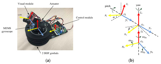
Figure 1.
(a) Components of VTISP; (b) Coordinatesof VTISP.
2.1. Gimbal Kinematic Model
Considering a dual-axial gimbals VTISP, the definition of the frame is shown in Figure 1b. The MEMS gyroscope and visual sensor are mounted on the inner gimbal and have the same axes direction, while the xi-axis is the LOS. The angular velocities of the rotations in frames OI, OO, and OB are represented by triads of vectors as follows. In [38], the disturbance of the base motion has been transformed into the inner gimbal by matrixes, which are shown in Equations (3) and (4).
ωI = (ωIx,ωIy, ωIz)T, ωO = (ωOx, ωOy, ωOz)T, ωB = (ωBx, ωBy, ωBz)T
The angular velocities in the vectors are detected by the MEMS gyroscope, which is referenced in an inertial frame.
The transformation matrix from frame OO to OI is RIO, and the inner gimbal rotations with a yi-axis are in angle α. The transformation matrix from frame OB to OO is ROB, and outer gimbal rotations with a zo-axis are in angle β.
The angular velocities of each axis of frame OB are transformed to OO by the Equation:
ωO = ROB·ωB + (0, 0, β’)T
The angular velocities of each axis of frame OO are transformed to OI by the Equation:
where α’ and β’ are the velocity in the rotation of the gimbals, which are driven by the actuators.
ωI = RIO·ωO+ (0, α’, 0)T
2.2. Gear-Driven Actuator
The gear-driven actuator can output large torque to drive the gimbals in the VTISP. It can minimize the disturbance from the eccentric torque of the payload in the system. That means the dual-axial gimbals with gear-driven actuators are more universal to kinds of payloads than the mass-stabilized direct-drive gimbals system, which is sensitive to eccentric torque. Although the gear trains couple the vehicle motions into the payload, it is easier to install, has higher torque in a small package, and is widely used in miniaturized underground vehicles. The actuator with an inner angular velocity loop has an approximate linear model in the relationship between an input signal and output velocity in Equation (5).
where ud is the pulse width of the square wave voltage by the actuator, θm’ is the output angular velocity, and km is a scale factor. The nonlinear and random influences in a backlash of gears driven can be considered as the total disturbance in the angular velocity loop. Then, the total disturbance can be observed and compensated by the LESO in the controller. So, the LADRC controller does not need a relatively precise model of the actuator when compared with other methods.
θm’ = km·ud
2.3. 2D Visual Model
The target is identified by a visual sensor. In Figure 2, a 2D image in a coordinate system with a dual-axial model can illustrate the output data of the visual sensor. The target in the FOV is coordinated with S(x, y), and the vector s = (w, v)T. Parameters w and v are the image coordinate frame parameters in axis x and y, respectively, which are the miss distance and quantified by the pixel value. The goal of the VTISP is to keep the target in the center of the FOV.
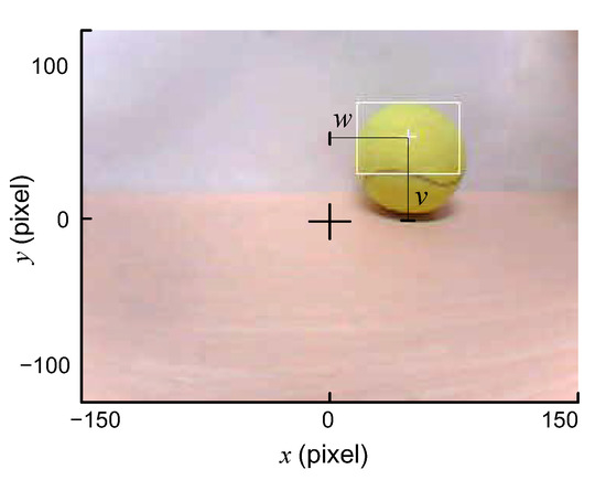
Figure 2.
The coordinate of FOV.
2.4. Visual Tracking Control Model
The VTISP control system is consists of an inner angular velocity loop and an outer visual loop. The angular velocities of the pitch and yaw gimbals are detected by the MEMS gyroscope, the data of which are the angular velocities in inertia as the feedback of the inner loop [39,40]. When the motions ωB from the base vehicle are introduced to the platform, the LOS can keep stable in inertia by the inner angular velocity loop. Visual tracking is achieved by adding an outer visual loop when the target is identified by the visual sensor, which can feedback values to vector s, so that the errors between the target and the center of FOV are identified.
A block diagram for a VTISP control system is illustrated in Figure 3. Where the vector ωm = (0, α’, β’)T, and combining ωB, the motion of the base vehicle can get ωI, which is the angular velocity of the LOS, as shown in Equations (3) and (4). The angle of the LOS in the inertia frame is represented by the vector θL = (0, σ, μ)T, which is the time integral result of vector ωI, as shown in Equation (6).
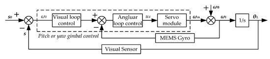
Figure 3.
Visual tracking and ISP control system.
The inner loop input variable ω0 has been calculated by s0–s, where s0 is the pixel of the location set in the FOV. The vector is s = (w, v)T, in which w and v are the feedback variables for the visual loop. To achieve a visual tracking function, the system keeps w = 0 and v = 0.
Pitch angle σ and yaw angle μ are fast adjusted to keep the target in the center of the FOV, which followed by the command variable ω0 generated by the visual loop.
3. LADRCin VTISP
The LADRC is introduced to the VTISP control system, as shown in Figure 4, which illustrates a pitch gimbal scheme such that Ry = (−sinβ, cosβ, 0).It is a control method to estimate and compensate for the total disturbance in the system, which includes external disturbance, model inaccuracy, and coupling. It is a dynamic process that does not utilize system parameters and specific models but uses the information between the inputs and outputs of the system to eliminate the disturbance in the system directly. The total disturbance is estimated by the linear extended state observer (LESO) from a simplified model and the output signal of the sensors, which can be compensated before generating the influences on the plant. The purpose of the method is to improve the performance in the dynamics and stability in the system. The LADRC consists of a tracking differentiator (TD), the proportional differential (PD) controller, and the LESO [41]. The TD can track the input signal and provide the smoothed high-order signals without the overshoot. It has almost the same performance as that of the PD but is easier to implement in practice than the nonlinear state error feedback (NLSEF) in the traditional ADRC. The LESO is modified by the TD, as shown in Figure 4, and discussed in detail as follows.
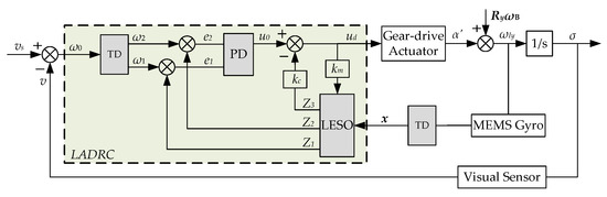
Figure 4.
A block diagram of LADRC controller in pitch control of the VTISP.
3.1. Tracking Differentiator (TD)
Let ω0 denote the input of the TD, which is converted from s0–s in either the pitch or the yaw angular velocity. As output variables, ω1 tracks ω0 and ω2 takes the derivative of ω0. The TD is described in a 2-order discrete form as follows [25]:
The angular velocity command ω0 contains random noise and nonlinear and transient disturbance generated by the outer visual loop. That process is implemented by a fast optimal control synthesis function fst(ω1(k) − ω0(k + 1),ω2(k),r,h0), and is expressed as follows:
where sign(a) is a limiting sign function, and the definitions of a and d are:
where the fst function utilizes the threshold variable d to detect the step components in ω0, r is the time scale of the tracking speed of ω0 to ω1, and h0 is the filter factor, which determines the filtering effect on the noise. The TD can track the input signal ω0 as soon as possible and avoid overshooting to the inner loop; then, the output ω1 and ω2 can be used in the PD controller.
3.2. Linear Extended State Observer (LESO)
The state observer is used to determine the internal state of the system by observing the external state of the system in different situations. The total disturbance can be extended to a state variable, which is included in the system expression, as shown in Equation (11).
That derivative process is expressed in Equation (12) and the structure diagram of the LESO is shown in Figure 4, and the observer is extended by the functions with gains, which are represented as follows:
The improved LESO is quoted and detailed in the argument in [41], as shown in Equation (12), which can achieve a good observational performance to high-order variables when ε1 is too small to achieve the approximation of z2 and z3. Moreover, the noise in the state variable can be decreased with the small gains. The provided parameters β1, β2, and β3 are turned properly, and the state variables of the system can be estimated in real-time by z1, z2, and z3.
Let the measured angular velocity by the MEMS gyroscope into that process: y = ωL, which is the state variable. However, there is high-frequency random noise in the output of the MEMS gyroscope, which is even worse in the low-cost one. The noise can be amplified in the differential variable of the MEMS gyroscope and influence the performance of the observation in the improved LESO. To solve that problem, we contribute to smoothing the 2-order velocity variable by the TD before being observed. The process is expressed in Equation (13).
where x1 is the state variable processed from ωL. The overshoots in x2 can be smoothed when r2 and h2 are turned properly. The performance of the LESO is improved when the observed variable z1 is very close to the state variable x1, which includes high-frequency random noise. As shown in the following results of the simulation, the improved LESO with the TD can provide smoother feedback for the PD controller to enhance the stability and response time.
Additionally, the TD processing for the LESO is the same function that processes the output signal of the visual sensor. That means high efficiency and a simplified program with software to implement in the application, which is particularly suitable for a low-cost hardware system.
3.3. Disturbance Compensation and PD Controller
The LESO output z1 and z2 are estimations of x1 and x2, and the tracking of the transient profile variables ω1 and ω2 is done by the PD controller. The influence of the model inaccuracy and coupling in the VTISP can be included in the total disturbance. Parameter z3 is the estimation of the total disturbance in the inner loop, which compensates the control variable u0 by kc·z3. Then, the final ud is a control signal impacting on the plant. The whole process can be expressed by the Equation as follows:
where k1 and k2 are the gains of the PD controller, and kc is the gain of the disturbance compensation.
4. Simulation and Verification
4.1. Influence of Luminance Variation
The influence of identification by luminance variation is shown in Figure 5, where the center of the identified field is stable in the view of the target in a lighting environment, marking a contrast to Figure 5b, which is unstable in darkness. The trajectory of the center of the identified field in the light and dark is shown in Figure 5c. Then, the signal of the miss distance to the center of view by the visual sensor is shown in Figure 5d, from the light to dark environment at 8 s. The random disturbance in the identification can be defined as n(t), where the relation in bound is |n(t)|≤dv, dv = 50, where dv is the radius in pixels of the target in the FOV. It is simplified in the visual model so that the distance between the target and the visual sensor cannot be regarded in the luminance variation conditions.
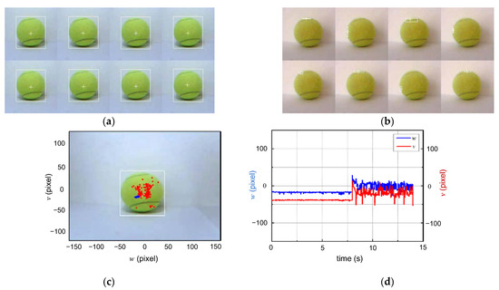
Figure 5.
Disturbance from varying illumination: (a) Target identifying in adequate lighting; (b) Target identifying in darkness; (c) Trajectory of central points of identified field in FOV; (d) The trajectory of disturbance with pixel in time varying.
4.2. Simulation of Control System
The random disturbance is introduced into the input signal that simulates the influence from the identification, which can be expressed as ω0 = Asin(t) + n(t). Then, the frequency of n(t) is 10 Hz and 0.1 kHz, respectively, and the amplitude is less than 15% of ω0 in a random disturbance. Let dv = 0.25 A, A = 75. The parameters in the TD are r = 3 and h0 = 10. The results of the simulation are shown in Figure 6. The output of the TD, ω1, is smooth without attenuation in either situation of frequency, and the performance as a filter in the 2-order output is better than that with the noise in the higher frequency.
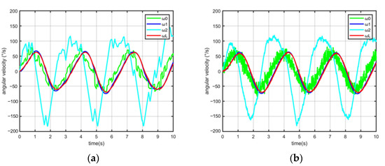
Figure 6.
The input signal with 10 Hz (a) and 0.1 kHz (b) random disturbance processed by TD.
As with the performance of the VTISP system in the simulation, the angular velocity y = ωL can track the input order ω1 exactly, which is processed by the TD. It proves that the LADRC with a PD controller is feasible for a VTISP system.
The performance of the improved LESO is shown in Figure 7. The state variable from the MESM gyroscope can be observed exactly by the LESO in the equation z1 = ∫(z2 − β1ε1)dt, ε1 = z1 − x1. The random noise in the MEMS gyroscope is enlarged in the differential process. As shown in Figure 7, the 2-order observed variable z2 is smoother than ωL’, which is the differential of the angular velocity y = ωL detected by the MEMS gyroscope. However, when the observed variable z1 is close enough to x1, z2 and z3 can be included in the noise in a high gain with β2 and β3 in the traditional LESO, as in the equation z2 = kmud+ ∫(z3-β2ε2)dt, which is improved by ε2 = z2 − x2. Moreover, the variable x2 is processed by the TD, which makes the observed variables of the LESO provide stable feedback in a 2-order variable so to improve the dynamic response time in the system. The total disturbance of the inner velocity loop is observed by z3 = ∫(−β3ε2)dt, which can be rapidly compensated by the control signal kc·z3.
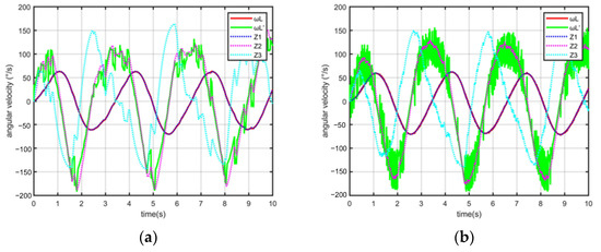
Figure 7.
The observed variables of LESO with state data from MEMS gyroscope. (a) 10 Hz; (b) 0.1 kHz.
It is concluded that the LADRC has a good performance in the tracking process in the situations described, which include model inaccuracy and random disturbance from the visual sensor and the MEMS gyroscope. The situations above restrict many other methods in the performance.
5. Experiment and Results
5.1. System for Experiments
To validate the superiority of the LADRC controller, experiments have been customized by a VTISP with a data acquisition system. It contains the VTISP, and a computer with a development and test environment, target, and light source for disturbance, as shown in Figure 8. The major constituent and parameters of the VTISP are shown in Table 1 and Table 2. Visual processes and tracking systems are implemented by the DSP in H7 and F4 series of ST microelectronics, which are programmed by the Python and C languages. The parameters turned in the program are shown in Table 3. Experiments are designed in comparison between the SMC and LADRC controller, referring to the performance when the illumination disturbance is induced into the system.
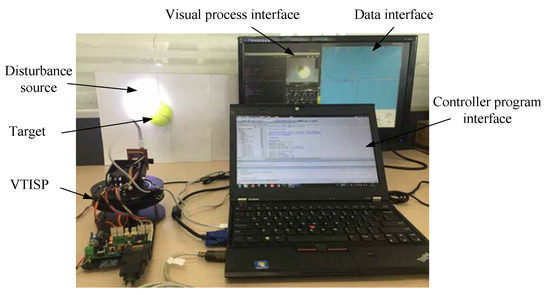
Figure 8.
Devices of VTISP experiment for testing.

Table 1.
Major components of VTISP.
Table 2.
Parameters of hardware system.
Table 3.
Parameters in the LADRC controller of the VTISP.
5.2. Performance of TD
To validate the performance of the TD in random disturbance rejection, the visual loop is test-independent. The control signal ud is disconnected fromthe actuator to set the LOS in a fixed angular position. The value ω0 is the variable of the vector s0 − s that expresses the pixel errors from the center of the FOV in the yaw motion. The output of the TD is ω1, such that the order of the angular velocity acts as the input variable of the PD. As shown in Figure 9a, the target is static at 10 pixels in the yaw. During the time 1.2~2 s and 3~4.5 s, the disturbance in the identification is induced to ω0 by a dark environment. The time integration is employed instead of the overshoot, as shown in the small diagram, making the following inner velocity loop stable. Then, the target motions in the FOV and the illumination are darkened during the time 1.75~4 s, as shown in Figure 9b. As shown in the small diagram, it is indicated that the overshoot introduced by the varying illuminations in ω0 is smoothed by the TD algorithm. Therefore, we can conclude that the TD has a satisfactory smooth performance in tracking the input signal to identify disturbances, and rarely lags in the output.
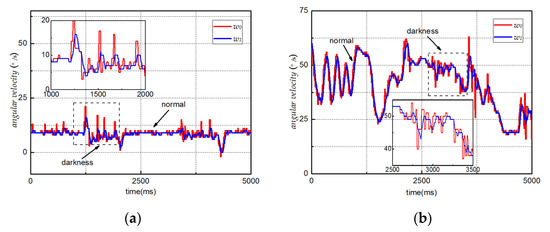
Figure 9.
Performance of TD in varying illuminations: (a) Static target in the FOV; (b) Moving target in the FOV.
5.3. Dynamic Performanceof Controller
Situation 1: The system is running with the inner angular velocity loop and the outer visual loop, and the target is static in the center of the FOV, with the illumination and the darkness suited alternately. As shown in Figure 10, the trajectories of the angular velocity and the tracking error in the pixels are the results of the static tracking test in the pitch gimbal. The target is identified exactly in a suitable illumination, and the LOS is stable between 0 s and 9 s. Then, the LOS is vibrated due to the disturbance introduced by the visual sensor after 9 s. The pitch angular velocity ωIy detected by the MEMS gyroscope is used to estimate the degree in vibration. The results are shown in Table 4, and the system with the SMC has maximum fluctuations in the angular velocity ωIy that are within ±80°/s. For the same disturbance from varying illuminations, it can be seen that the maximum fluctuations of the LADRC in the angular velocity ωIy are within ±40°/s. Thus, it proves that the LADRC has a better disturbance-rejection ability than the SMC.
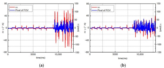
Figure 10.
Performance of visual tracking loop with static target in varying illuminations. (a) SMC; (b) LADRC.
Table 4.
Results of test in situation 1.
Situation 2: The system with a step in the visual input is implemented that completes the process to capture, and the trajectories of the angular velocity and the tracking error in pixels are shown in Figure 11. It has a bias in the pitch between the target and the center of the FOV, which is about 100 pixels. The system is running initially with the inner angular velocity loop and then switches to the outer visual loop at 0.3 s. The target is identified in a dark illumination during the process to capture, and the identified disturbance is dv = 25 in each test. As shown in Figure 11a, the angular velocity of the LOS is stable after 1 s, and the process to capture is between 0.3 s and 1 s. As a contrast, in Figure 11b, which show the results of the LADRC test, the process to capture is between 0.3 s and 0.75 s. The time during the capture is represented by tc, and the data of the test is shown in Table 5. The maximum overshoot in ωIy during the capture by the SMC is about 80°/s, which, as a contrast, is about −25°/s by the LADRC. There are random fluctuations in the stable process which are within ±30°/s by the SMC. By contrast, the more moderate fluctuations in ωIy are within ±20°/s by the LADRC. It proves that the VTISP with the LADRC can capture the target more stably in varying illuminations. The performance is better than the SMC, which has large fluctuations in the whole process.
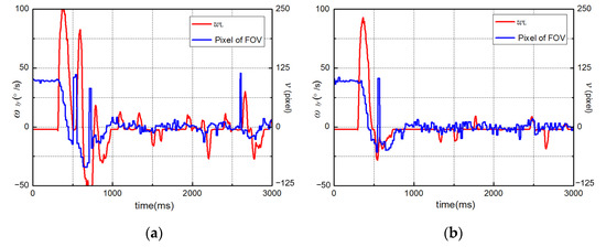
Figure 11.
Performance of capturing the target in varying illuminations. (a)SMC;(b) LADRC.
Table 5.
Results of test in situation 2.
Situation 3: To test the dynamic performance of the VTISP with the LADRC controller in the tracking process, the target takes a pendulum movement in the yaw with the illumination and dark suited alternately. The trajectories of the angular velocity ωIz and tracking error w in the pixels are shown in Figure 12. During the tracking process in a suited illumination from 0 s to 5 s, the tracking error w is within ±30 pixels in the FOV. When the illumination is switching to darkness at 5 s, the VTISP is adjusted at 0.5 s to deal with the disturbance from the visual sensor. As illustrated in the trajectories of the test after 5.5 s, the maximum fluctuation in w is within ±15 pixels, and the target can be still tracked almost at the same performance. It is compared that the target has been lost when the disturbance in illumination is introduced to the SMC in a dynamic process testing. Therefore, we can conclude that the LADRC has a better dynamic performance in a VTISP system.
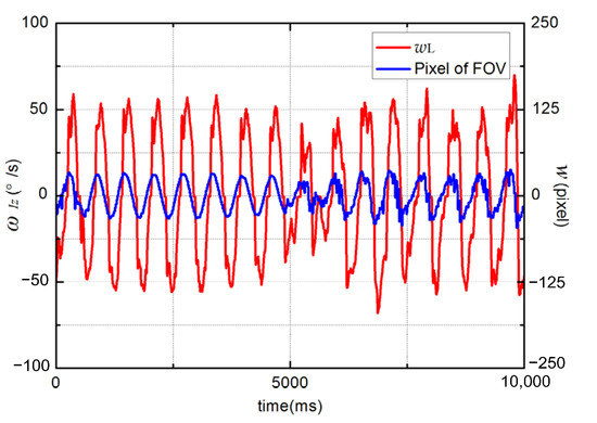
Figure 12.
Performance of LADRC in tracking the target in varying illuminations.
6. Conclusions
The performance of the system in the VTISP can be influenced by the disturbance from the target identification in an illumination-varying environment. To solve this problem, the LADRC is proposed so that the disturbance can be rejected in a control system. That method is lower cost and simpler than the computer vision algorithm, as well as more suitable for a miniaturized VTISP. Firstly, the influence from the visual sensor can be reduced by the TD in the controller. Secondly, a smoothed accelerated velocity state variable can be observed by the improved LESO, which is from the MEMS gyroscope during a tremulous LOS. The loop control with an angular velocity in the second-order improves the stability and the dynamic performance of the VTISP in an illumination-varying environment. Meanwhile, the mathematical model of the VTISP and the controller is established, and the feasibility of the method in the model inaccuracy and random disturbance situations is verified by simulation. Finally, contrastive experiments with the SMC are designed to verify the superior performance of the controller in the situation of model inaccuracies and random disturbances.
The VTISP with the LADRC controller will be installed on a small ground vehicle to implement actual experiments in the future.
Author Contributions
T.F. and Y.G. conceived the idea; T.F.designed the software, collected the data, and analyzed the experimental data; L.G. collected the related resources and supervised the experiment; T.F. prepared original draft and final article; C.Q. proposed the comment for the paper and experiment. All authors have read and agreed to the published version of the manuscript.
Funding
This work is sponsored by the National Natural Science Foundation of China (NSFC.61803118), the Department of Science and Technology of Heilongjiang Province (LH2021F018), the Science and Technology Research Program of Chongqing Municipal Education Commission (KJZD-K202104701), and the Post Doc. Foundation of Heilongjiang Province(LBH-Z17053).
Institutional Review Board Statement
Not applicable.
Informed Consent Statement
Not applicable.
Data Availability Statement
Data sharing is not applicable.
Conflicts of Interest
The authors declare no conflict of interest.
References
- Das, S.; Kale, A.; Vaswani, N. Particle filter with a mode tracker for visual tracking across illumination changes. IEEE Trans. Image Process. 2012, 21, 2340–2346. [Google Scholar] [CrossRef] [PubMed]
- Al Delail, B.; Bhaskar, H.; Zemerly, M.J.; Al-Mualla, M. Robust likelihood model for illumination invariance in particle filtering. IEEE Trans. Circ. Syst. Video Technol. 2018, 28, 2836–2848. [Google Scholar] [CrossRef]
- Gurkan, F.; Gunsel, B.; Ozer, C. Robust object tracking via integration of particle filtering with deep detection. Digit. Signal Process. 2019, 87, 112–124. [Google Scholar] [CrossRef]
- Wu, H.; Xu, X.R.; Chu, J.B.; Duan, L.; Siebert, P. Particle swarm optimization-based optimal real Gabor filter for surface inspection. Assenbly Autom. 2019, 39, 963–972. [Google Scholar] [CrossRef]
- Moghaddasi, S.S.; Faraji, N. A hybrid algorithm based on particle filter and genetic algorithm for target tracking. Expert Syst. Appl. 2020, 147, 113188. [Google Scholar] [CrossRef]
- Wang, F.S.; Wang, Y.B.; He, J.J.; Sun, F.M.; Li, X.C.; Zhang, J.X. Visual object tracking via iterative ant particle filtering. IET Image Process. 2020, 14, 1636–1644. [Google Scholar] [CrossRef]
- Luo, M.; Chang, X.; Nie, L.; Yang, Y.; Alexander, G.; Zheng, Q. An Adaptive Semisupervised Feature Analysis for Video Semantic Recognition. IEEE Trans. Cybern. 2018, 48, 648–660. [Google Scholar] [CrossRef]
- Chen, K.; Yao, L.; Zhang, D.; Wang, X.; Chang, X.; Nie, F. A Semisupervised Recurrent Convolutional Attention Model for Human Activity Recognition. IEEE Trans. Neural Netw. Learn. Syst. 2020, 31, 1747–1756. [Google Scholar] [CrossRef]
- Miller, R.; Mooty, G.; Hilkert, J.M. Gimbal system configurations and line-of-sight control techniques forsmall UAV applications. In Airborne Intelligence, Surveillance, Reconnaissance (ISR) Systems and Applications X; SPIE: Paris, France, 2013; p. 8713. [Google Scholar]
- Gasparovic, M.; Jurjevic, L. Gimbal Influence on the Stability of Exterior Orientation Parameters of UAV Acquired Images. Sensors 2017, 17, 401. [Google Scholar] [CrossRef] [Green Version]
- Rodin, C.D.; Andrade, F.A.D.; Hovenburg, A.R.; Johansen, T.A. A survey of practical design considerations of optical imaging stabilization systems for small unmanned aerial systems. Sensors 2019, 19, 4800. [Google Scholar] [CrossRef] [Green Version]
- Zhang, D.; Yao, L.; Chen, X.; Wang, S.; Chang, X.; Liu, Y. Making Sense of Spatio-Temporal Preserving Representations for EEG-Based Human Intention Recognition. IEEE Trans. Cybern. 2020, 50, 3033–3044. [Google Scholar] [CrossRef] [PubMed]
- Zhou, X.Y.; Gong, G.H.; Li, J.P.; Zhang, H.Y.; Yu, R.X. Decoupling control for a three-axis inertially stabilized platform used for aerial remote sensing. Trans. Inst. Meas. Control 2015, 37, 1135–1145. [Google Scholar] [CrossRef]
- Ke, D.; Shuang, C.; Dejie, K.; Honghai, S. Discrete-Time Direct Model Reference Adaptive Control Application in a High-Precision Inertially Stabilized Platform. IEEE Trans. Ind. Electron. 2019, 66, 358–367. [Google Scholar]
- Altan, A.; Hacioglu, R. Model predictive control of three-axis gimbal system mounted on UAV for real-time target tracking under external disturbances. Mech. Syst. Signal Process. 2020, 138, 106548. [Google Scholar] [CrossRef]
- Kim, S.B.; Kim, S.H.; Kwak, Y.K. Robust control for a two-axis gimbaled sensor system with multivariable feedback systems. IET Control. Theory Appl. 2010, 4, 539–551. [Google Scholar] [CrossRef]
- Hong, S.; Cho, K.D. Kinematic algorithms and robust controller design for inertially stabilized system. IEEE-ASME Trans. Mechatron. 2014, 19, 76–87. [Google Scholar] [CrossRef]
- Songoing, J.; Zhou, D.; Sun, J.; Qi, Z. Robust control with compensation of adaptive model for dual-stage inertially stabilized platform. J. Cent. South Univ. 2018, 25, 2615–2625. [Google Scholar] [CrossRef]
- Safa, A.; Abdolmalaki, R.Y. Robust output feedback tracking control for inertially stabilized platforms with matched and unmatched uncertainties. IEEE Trans. Control Syst. Technol. 2019, 27, 118–131. [Google Scholar] [CrossRef]
- Lee, D.H.; Tran, D.Q.; Kim, Y.B.; Chakir, S. A robust double active control system design for disturbance suppression of a two-Axis gimbal system. Electronics 2020, 9, 1638. [Google Scholar] [CrossRef]
- Zou, Y.; Lei, X.S. A compound control method based on the adaptive neural network and sliding mode control for inertial stable platform. EuroCmputing 2015, 155, 286–294. [Google Scholar] [CrossRef]
- Zhou, Z.M.; Zhang, B.; Mao, D.P. MIMO fuzzy sliding mode control for three-axis inertially stabilized platform. Sensors 2019, 19, 1658. [Google Scholar] [CrossRef] [PubMed] [Green Version]
- Ding, Z.; Feng, Z.; Liang, Y.; Zhe, J.; Zhu, J. Anti-Disturbance Neural-Sliding Mode Control for Inertially Stabilized Platform With Actuator Saturation. IEEE Access 2019, 7, 92220–92231. [Google Scholar] [CrossRef]
- Kumar, S.S.; Anitha, G. A novel self-tuning fuzzy logic-based PID controllers for two-axis gimbal stabilization in a missile seeker. Int. J. Aerosp. Eng. 2021, 2021, 1–12. [Google Scholar] [CrossRef]
- Han, J. From PID to active disturbance rejection control. IEEE Trans. Ind. Electron. 2009, 56, 900–906. [Google Scholar] [CrossRef]
- Gao, Z. Scaling and bandwidth-parameterizationbased controller tuning. In proceedings of the 2003 American Control Conference, Denver, CO, USA, 4–6 June 2003; pp. 4989–4996. [Google Scholar]
- Xia, Y.; Dai, L.; Fu, M.; Li, C.; Wang, C. Application of active disturbance rejection control in tank gun control system. J. Frankl. Inst. 2014, 351, 2299–2314. [Google Scholar] [CrossRef]
- Zhou, X.; Chao, Y.; Zhao, B.; Zhao, L.; Zhu, Z. A High-Precision Control Scheme Based on Active Disturbance Rejection Control for a Three-Axis Inertially Stabilized Platform for Aerial Remote Sensing Applications. J. Sens. 2018, 2018, 7295852. [Google Scholar] [CrossRef]
- Changrui, B.; Zhou, Z. A least mean square based active disturbance rejection control for an inertially stabilized platform. Opt-Int. J. Light Electron Opt. 2018, 174, 609–622. [Google Scholar]
- Behzad, A.; Amin, N. Hardware Implementation of an ADRC Controller on a Gimbal Mechanism. IEEE Trans. Control Syst. Technol. 2018, 26, 2268–2275. [Google Scholar]
- Wang, F.; Wang, R.; Li, E.; Zhang, W. Stabilization Control Method for Two-Axis Inertia Stabilized Platform Based on Active Disturbance Rejection Control with Noise Reduction Disturbance Observe. IEEE Access 2019, 7, 99521–99529. [Google Scholar] [CrossRef]
- Zhou, X.; Yuan, J.; Qiang, Z.; Cai, T. Dual-rate-loop control based on disturbance observer of angular acceleration for a three-axis aerial inertially stabilized platform. ISA Trans. 2016, 63, 288–298. [Google Scholar] [CrossRef]
- Zhou, X.; Zhun, J.; Zhao, B.; Li, J. Extended state observer/proportion integration differentiation compound control based on dynamic modelling for an aerial inertially stabilized platform. Int. J. Adv. Robot. Syst. 2017, 2017, 1–10. [Google Scholar] [CrossRef]
- Zhou, X.; Gao, H.; Zhao, B.; Zhao, L. A GA-based parameters tuning method for an ADRC controller of ISP for aerial remote sensing applications. ISA Trans. 2018, 81, 318–328. [Google Scholar] [CrossRef] [PubMed]
- Huynh, T.; Tran, M.T.; Lee, D.H. A Study on Vision-Based Back-stepping Control for a Target Tracking System. Actuators 2021, 10, 105. [Google Scholar] [CrossRef]
- Guo, J.; Yuan, C.; Zhang, X.; Chen, F. Vision-based target detection and tracking for a miniature pan-tilt inertially stabilized platform. Electronics 2021, 10, 2243. [Google Scholar] [CrossRef]
- Zhao, C.; Huang, Y. ADRC based input disturbance rejection for minimum-phase plants with unknown orders and/or uncertain relative degrees. J. Syst. Sci. Complex. 2012, 25, 625–640. [Google Scholar] [CrossRef]
- Ekstrand, B. Equations of motion for a two-axes gimbal system. IEEE Trans. Aerosp. Eelctron. Syst. 2001, 37, 1083–1091. [Google Scholar] [CrossRef]
- Hurak, Z.; Rezac, M. Image-based pointing and tracking for inertially stabilized airborne camera platform. IEEE Trans. Control Syst. Technol. 2012, 20, 1146–1159. [Google Scholar] [CrossRef]
- Masten, M.K. Inertially stabilized platforms for optical imaging systems—Tracking dynamic targets with mobile sensors. IEEE Control Syst. Mag. 2008, 28, 47–64. [Google Scholar]
- Zhang, Z.; Cheng, J.; Guo, Y. PD-Based Optimal ADRC with Improved Linear Extended State Observer. Entropy 2021, 23, 888. [Google Scholar] [CrossRef]
Publisher’s Note: MDPI stays neutral with regard to jurisdictional claims in published maps and institutional affiliations. |
© 2022 by the authors. Licensee MDPI, Basel, Switzerland. This article is an open access article distributed under the terms and conditions of the Creative Commons Attribution (CC BY) license (https://creativecommons.org/licenses/by/4.0/).