Article

A Battery-Powered Fluid Manipulation System Actuated by Mechanical Vibrations

Department of Mechanical Engineering, Aydin Adnan Menderes University, Aydin 09010, Turkey
*
Author to whom correspondence should be addressed.
Actuators 2022, 11(5), 116; https://doi.org/10.3390/act11050116
Submission received: 28 March 2022 / Revised: 15 April 2022 / Accepted: 20 April 2022 / Published: 21 April 2022
(This article belongs to the Section Miniaturized and Micro Actuators)

Abstract

:
Miniaturized fluid manipulation systems are an important component of lab-on-a-chip platforms implemented in resourced-limited environments and point-of-care applications. This work aims to design, fabricate, and test a low-cost and battery-operated microfluidic diffuser/nozzle type pump to enable an alternative fluid manipulation solution for field applications. For this, CNC laser cutting and 3D printing are used to fabricate the fluidic unit and casing of the driving module of the system, respectively. This system only required 3.5-V input power and can generate flow rates up to 58 µL/min for water. In addition, this portable pump can manipulate higher viscosity fluids with kinematic viscosities up to 24 mPa·s resembling biological fluids such as sputum and saliva. The demonstrated system is a low-cost, battery-powered, and highly versatile fluid pump that can be adopted in various lab-on-a-chip applications for field deployment and remote applications.

1. Introduction

Portable fluid actuation is an important function for point-of-care diagnostics and lab-on-a-chip devices [1,2,3]. Fluid manipulation on a small scale is in general an important capacity that has been applied in numerous applications [4]. For example, on-chip chemical synthesis or bioanalyses require precise and controllable manipulation of different analytes and reagents with various viscosities [5,6,7]. While these operations can be fulfilled using traditional bench-top equipment, point-of-care medical implementations and field applications demand mobile and simple fluid handling systems that have often been targeted by microfluidic fluid manipulation platforms [8,9,10,11]. However, current microfluidic pumps are generally expensive to fabricate because they rely on complex cleanroom fabrication tools and depend on bulky external driving units such as power amplifiers and function generators [12,13,14]. These factors prevent the application of most microfluidic fluid pumps in resource-limited environments. In an ideal case, a miniaturized fluid actuation platform should be low-cost, easy to fabricate, easy to operate in field applications, and have a small footprint, including driving and actuation units. However, the majority of the current microfluidic fluid manipulation systems limit true realization of laboratory on chip applications due to their dependence on complex working mechanisms and peripheral equipment [15,16,17,18,19].
There is a constant effort to achieve low-cost and simple microfluidic fluid manipulation relying on various external mechanisms such as magnetic [13], dielectric [20], acoustic [21], peristaltic [22,23], chemical [24], electrohydrodynamic [25,26], and finger actuation [27]. Magnetic pumps are generally designed to couple an external magnetic field to an internal moving part to drive fluid flow. In a recent example, Cook et al. demonstrated a three dimensional (3D) printed device that had a magnetic impeller to generate recirculating flow conditions for organ on-chip applications [28]. In this device, the external magnetic field is provided by permanent magnets rotated by a computer fan to control the rotation of the internal impeller. Even though this device is relatively simple compared to the more involved magnetically actuated microfluidics pumps, internal moving parts and external power requirements are net desired for field applications. There are several types of acoustically driven microfluidics pumps, including oscillating sharp-edged, trapped microbubble, and surface acoustic based pumps [29,30,31]. The main drawback of these acoustically powered pumps is their demanding fabrication requirements, which can only be carried out in well-equipped facilities. Similarly, dielectric and on-chip integrated peristaltic pumps involve the fabrication of intricate microfluidic geometries and metal electrodes to achieve on-chip flow control. Another group of microfluidic pumps are valveless diffuser/nozzle type systems that utilize piezoelectric actuators to continuously expand and contract a small volume and generate net flow by implementing the diffuser/nozzle type channels [32,33,34]. Tesla valve-based pumps also fall into this category, in which fluid flow is restricted in one dimension by implementing a tesla valve structure to obtain net flow in one direction [24]. These systems are relatively simple compared to the magnetic, acoustic, electrohydrodynamic, chemical, and dielectric-based pumps, but the valveless pumps usually still require microfabricated actuation layers and high driving voltages, which add further complexity. There are also various valve-based fluid pumps that rely on flow-directing valve mechanisms to drive directional fluid flow [22]. These pumps also employ different membrane actuation mechanisms [35,36]. Finger-actuated manual microfluidic pumps are promising alternatives for simpler lab-on-chip applications, but the flow rate control in these pumps is not well-controlled [37]. Overall, the existing microfluidic fluid handling platforms are generally bulky, expensive, and complex, which hinders true mobility and remote applications of lab-on-chip platforms. Therefore, there is still a need for a simpler, low-cost, and efficient microfluidic pump.
In this work, a battery-powered, portable, and controllable microfluidic pumping system was demonstrated based on a diffuser/nuzzle actuation mechanism. To do this, a disc-shaped vibration motor was attached to a thin poly(dimethylsiloxane) (PDMS) membrane, which was incorporated into a laser-machined poly(methyl methacrylate) (PMMA) microfluidic device. A 9-Volt battery was used to operate the fluidic pump through a direct current (DC) voltage regulator module, which enabled adjustable output and voltage display. This simple device provided controllable fluid pumping capability with flow rates up to 58 µL/min for water. Different concentrations of poly(ethylene glycol) (PEG) solutions were also tested, and solutions with up to 24 mPa·s kinematic viscosities were pumped through the device. Owing to its simplicity, low-cost, and functionality, this device can be adopted in various lab-on-a-chip applications.

2. Materials and Methods

The fluidic channel fabrication was performed using a CO2 laser CNC machine (STJ1390, Stylecnc, Shandong, China). The fluidic part consists of 4 layers, including a 0.5-mm thick base, a 2-mm thick channel, a 200-micrometer thick PDMS membrane and a 2-mm thick top bracket. PDMS is a highly elastic and transparent elastomer that has been extensively used in microfluidic device applications [38]. Before laser cutting, 90-micrometer thick two-sided water-based acrylic adhesive sheets were applied to the front and back of the 2-mm thick channel layer. For the PDMS layer, liquid PDMS part A and curing part B (Sylgard 184, Dow-Corning, Midland, MI, USA) were mixed at a 10:1 (w/w) ratio and poured into a 6-inch flat petri dish. The thickness of the PDMS membrane was measured, and the process was calibrated to obtain a 200-micrometer thick layer. After curing at 60 °C for 2 h, the PDMS layer was cut to the size of the outer perimeter of the top bracket by tracing with a razor. After that, the bottom layer and the PDMS layer were pressed on the adhesive front and back side of the channel layer. The inlet and the outlet of the device were open through the PDMS layer using a biopsy punch. Finally, the top bracket layer was pressed on top of the PDMS layer and metric 3 screws were bolted through the device to provide better bonding. Dimensions of the diffuser and nozzle were chosen empirically and based on the similar microfluidic pumps reported in the literature [32,39].
A vibration motor (VC1034B018F, Vybronics, Brooklyn, NY, USA) of 10-mm diameter was epoxy bonded on the PDMS layer aligning with the actuation chamber of the fluidic channel. The vibration motor was connected to the output of a voltage regulator module based on an LM2596 simple switcher (Texas Instruments, Dallas, TX, USA). This module is equipped with a 7-segment display and is rated for input voltages between 3 and 35 V and output voltages of 1 to 30 V. The 9-V battery and voltage regulator were fitted into a 3D printed housing and a PMMA panel. An actual picture of the assembled device, as well as its schematics and an exploded view of the layers of the fluidic device, are shown in Figure 1.
Yeast cells (Saccharomyces cerevisiae) were used to evaluate the effect of pumping on cell viability. Yeast cells were prepared by incubating dry yeast cells in 35 °C deionized (DI) water, and cell concentrations of ~5 × 10⁵ cells/mL were used in the pumping system. For the evaluation of the cell viability, methylene blue dye was used. For this, 0.1 g methylene blue was dissolved in 100 mL DI water, and 0.1% (w/v) dye solution was added in the yeast cells. A standard hemocytometer was used to count the dead cells to calculate viability percentages at different pumping rates.
Fluid pumping experiments were conducted under an inverted microscope (OX.2053-PLPH, Euromex, Arnhem, The Netherlands), and images were recorded using an HD camera (HDUltra, Euromex, Arnhem, The Netherlands) and a high-speed camera (EX-FC100, Casio, Tokyo, Japan). Flow rates were characterized by tracing 5 micrometer diameter polystyrene beads (Sigma Aldrich, Burlington, MA, USA) mixed into the pumped fluid [21,29]. Net directional displacements of the beads were measured to find fluid speeds, which were converted to flow rates by multiplying by the cross-sectional area of the straight part of the channel that had a width of 3.6 mm close to the outlet of the fluidic channel. Different concentrations of poly(ethylene glycol) (PEG) solutions were prepared to test the performance of the pumping system with high viscosity fluids.
The flow diagram of the whole system is shown in Figure 2. The 9-V battery supplies the voltage regulator module, which provides voltage output via a 7-segment display. A potentiometer on the module enables fine control of the applied voltage to the vibration motor, which in turn changes the volume in the actuation chamber of the fluidic channel to generate directional net flow. The system is independent of additional peripheral units and does not require a power outlet to operate.

3. Results

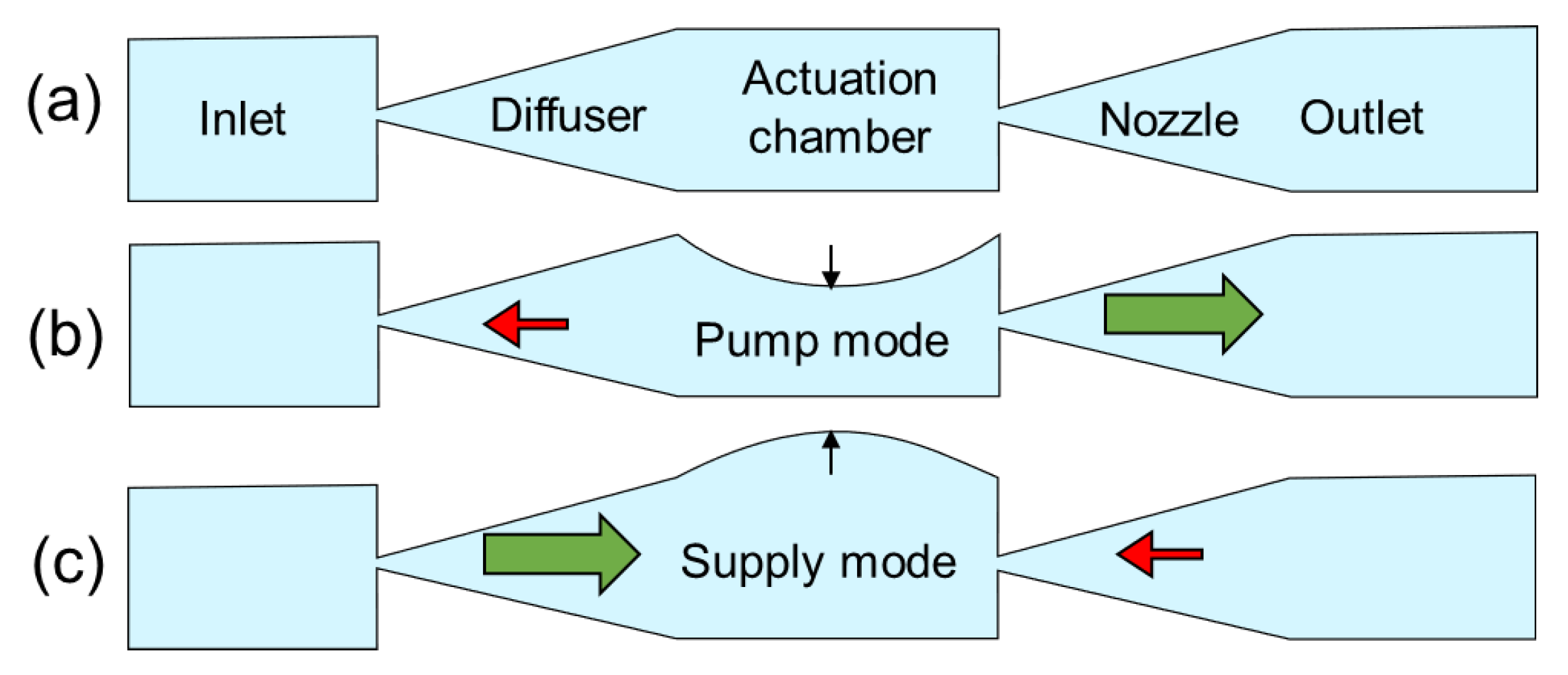
3.1. Working Mechanism

The presented microfluidic pump is a diffuser/nozzle type fluid manipulation system. The theoretical volume flow rate of this system can be approximated as the following [32]:
Q = Δ V   ω π   ( k 1 / 2 1 k 1 / 2 + 1 ) ,
where ΔV is the volume change due to membrane contraction and expansion, w is the frequency of the membrane vibration and k is the diffuser efficiency, which mainly depends on the geometry of the diffuser and the fluid viscosity. There are two main parameters that can increase the flow rate of the pumping system: volume change and the membrane frequency. The volume change in the system depends on the oscillation amplitude of the membrane, such that the larger the oscillation amplitude the higher the volume change. In the presented system, the maximum frequency of the vibration motor is 13,000 rpm, corresponding to 216 Hz, which occurs at the maximum applied voltage of 3.5 V. Considering the maximum frequency, an approximate volume change of 0.14 mm3 that occurs in the actuation chamber, and an estimated diffuser efficiency of 1.5, the flow rate is calculated to be ~58 µL/min. The flow rate of the pump is controlled by controlling the input voltage of the vibration motor from 1 V to 3.5 V. The working mechanism of the pump is illustrated in Figure 3. As the vibration motors vibrate, the PDMS membrane moves up and down, which provides the pump and supply modes. In the pump mode, the membrane is pushed down, decreasing the volume in the actuation chamber and generating a larger fluid flow towards the right due the diffuser/nozzle effect. In the reverse mode, the actuation chamber is filled with liquid, which is drawn mostly from the reservoir located on the right side.

3.2. Water Pumping Experiments

For the characterization of the pumping flow rates, the inlet and outlet of the device were connected with the same tubing to have a closed loop after filling the entire fluidic channel with the water and polystyrene particle solution. For each applied voltage value, polystyrene beads were tracked (Figure 4a), and the flow rates were calculated. Flow rate versus applied voltage values is given in Figure 4b. As it is seen, the flow rate of the water increases as the applied voltage is increased. The applied voltage value is limited to 3.5 V due to the manufacturer’s maximum rating. With the current control unit and the vibration motor, the flow rate resolution was found to be approximately 1 µL/min, which can be further improved with a better voltage regulator. The maximum flow rate is observed to be around 55 µL/min, which has a 5% error compared to the estimated flow rate of 58 µL/min using the Equation (1).

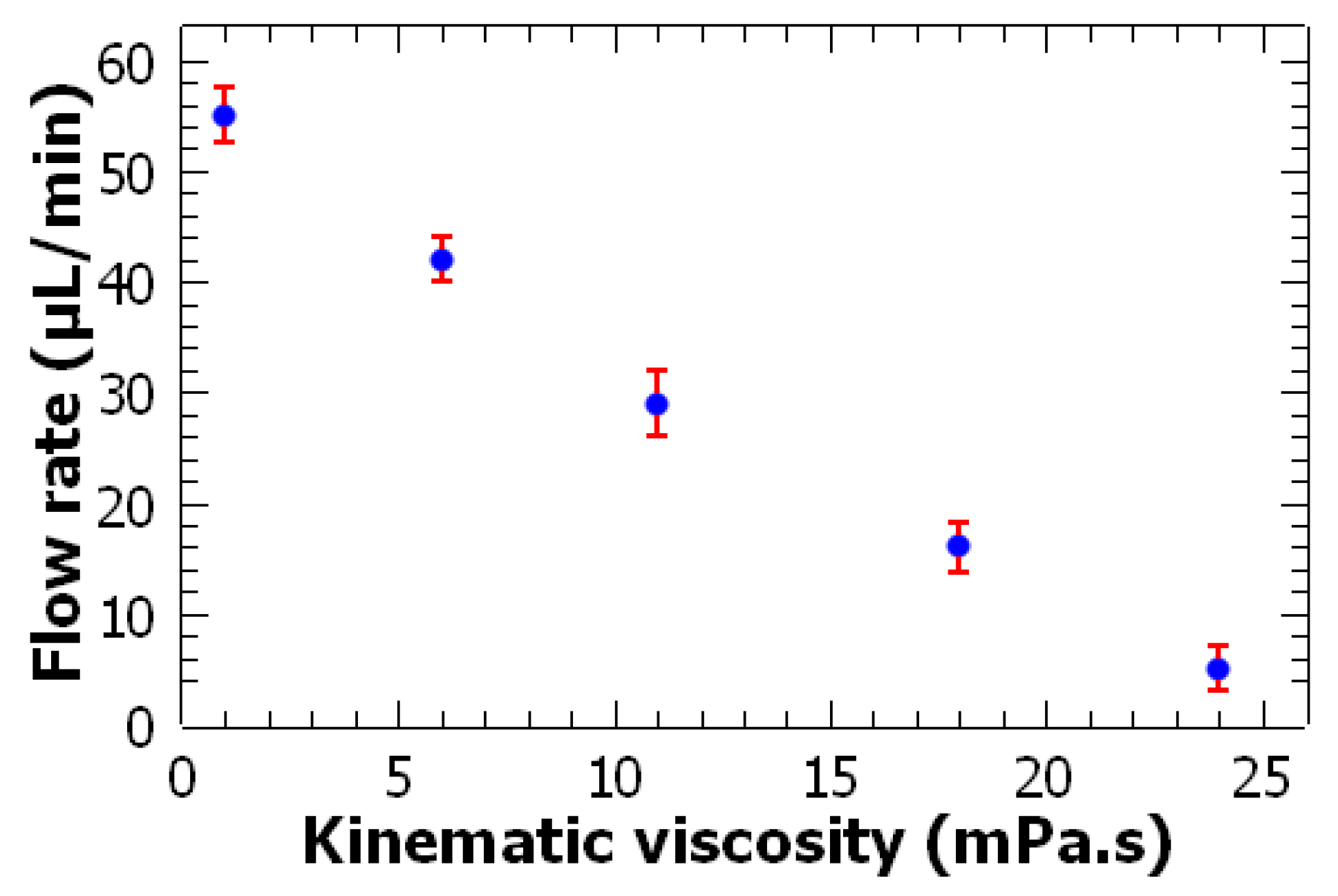
3.3. High Viscosity Fluid Pumping

To evaluate the efficiency of the pumping system with different viscosity fluids, different concentrations of PEG solutions were mixed with the polystyrene beads. For these experiments, the applied voltage value was fixed at 3.5 V. Figure 5 shows the variation of the flow rate as the viscosity of the fluid is increased. As a comparison, pure water is also included in the plot. As is evident from the graph, when the viscosity is increased, the pumping flow rate drops. For the highest viscosity value of 24 mPa·s, a flow rate of 7 µL/min is achieved.

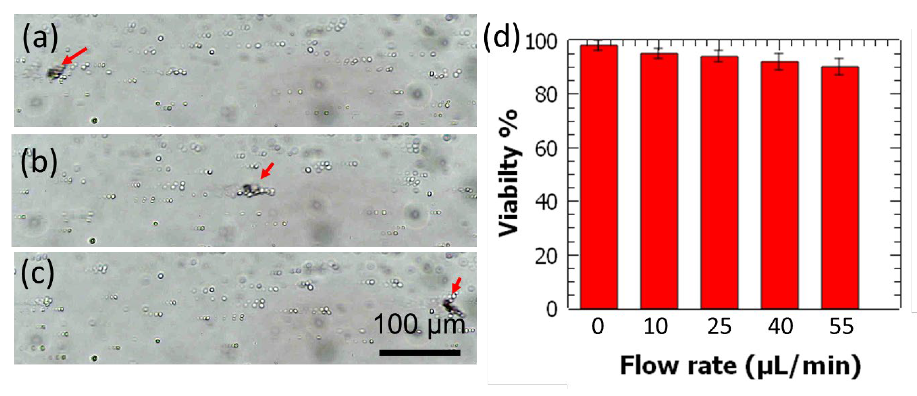
3.4. Cell Pumping and Viability Evaluation

Considering the potential of the pumping system to be used in biological studies, yeast cells were pumped at increasingly higher flow rates, and their viability ratios were characterized using methylene blue staining dye. Methylene blue that enters the dead cells forms a blue coloration and hence enables dead cell counting. Cells were pumped from the device and collected from the outlet to be stained and counted in a standard hemocytometer. Figure 6 shows the characterization of viability ratios of the yeast cells that are pumped at different flow rates. As a control, yeast cells that were not passed through the pumping device were also analyzed, and their viability ratio was given in Figure 6d. It was observed that the viability of the yeast cells was over 90% for flow rates up to 58 µL/min, which is the maximum flow rate attained for the highest voltage value.

4. Discussion

Lab-on-a-chip systems that involve microfluidic channels require fluid manipulation systems to perform sample-preparation, bioanalysis, testing, and diagnostics [40,41]. The presented device in this work is a battery operated and low-cost fluid manipulation system that is shown to generate controllable flow rates. There are few other approaches in the literature that focus on device mobility and small-footprint that could support field deployment in remote applications [42,43]. Compared to most of the existing portable lab-on-a-chip devices or enabling peripheral equipment, our battery-operated fluid pumping system is simpler in terms of the required components and fabrication process, which are readily available around the world, such as the vibration motor, voltage regulator module, and 3D printing. As a result of this simplicity, the system cost is also low, falling between 5 and 10 USD depending on the type of voltage regulator module.
There is a wide-range of microfluidic pumps available in the literature that can be categorized into passive and active systems [44,45]. The passive pumping systems do not allow control of flow rate and they are usually not as precise as the active pumps. The majority of the active microfluidic pumps reported in the literature are dependent on bulky peripheral units and require high powers [12,46]. The presented system is capable of generating controllable flow manipulation with a maximum flow rate of 58 µL/min flow rate at only 3.5 V. Furthermore, higher viscosity fluids up to 24 mPa·s could be pumped in this device at the same maximum voltage value, and a flow rate of 7 µL/min can be obtained. Higher viscosity fluids are used in the system to demonstrate the capability of this system to handle biological samples and chemicals with higher viscosities. It is also important to note that vibration motors rated for higher driving voltages that can output higher rpm values could increase the performance of this pumping system.
One of the advantages of the presented system is the low-power requirement, which is critical for field deployments and point-of-care applications. Due to the very low input voltage rating, this system can potentially work through a power input from a cell phone. This could further simplify the pumping system and lower its cost by eliminating the battery and the voltage regulator module. The number of smartphones used in developing countries is rapidly growing, which is basically a readily available power source and processing unit that can be implemented to power and control the pumping system. This infrastructure carries an important potential for the future of portable fluid handling systems for lab-on-a-chip applications in low-resourced environments.

5. Conclusions

In this work, a simple battery-powered microfluidic flow manipulation system is demonstrated. This system is low-cost and only requires a 9-V battery to work, which enables independent operation in field applications. In the fabrication process of the system, only 3D printing and rapid laser prototyping are involved, which are relatively simple and low-cost methods compared to cleanroom microfabrication. Considering the achievable flow rates and the range of fluids with viscosities up to 24 mPa·s, this pumping system is versatile and can be adopted in various on-chip applications, including sample preparation, analysis, and detection. Specifically, the presented system is suitable for field applications where portable operation is critical.

Author Contributions

Conceptualization, A.Ö.; methodology, A.Ö. and F.A.; formal analysis, A.Ö. and F.A.; resources, A.Ö.; original draft preparation, A.Ö. and F.A.; writing—review and editing, A.Ö. and F.A.; supervision, A.Ö. All authors have read and agreed to the published version of the manuscript.

Funding

The Scientific and Technological Research Council of Turkey (TUBITAK) 3501 grant (Project No. 218M257).

Institutional Review Board Statement

Not applicable.

Data Availability Statement

Not applicable.

Acknowledgments

We thank Emre Ak for his suggestions and recommendations. This work was supported by The Scientific and Technological Research Council of Turkey (TUBITAK) 3501 grant (Project No. 218M257).

Conflicts of Interest

The authors declare no conflict of interest.

References

  1. Nasseri, B.; Soleimani, N.; Rabiee, N.; Kalbasi, A.; Karimi, M.; Hamblin, M.R. Point-of-care microfluidic devices for pathogen detection. Biosens. Bioelectron. 2018, 117, 112–128. [Google Scholar] [CrossRef] [PubMed]
  2. Akkoyun, F.; Gucluer, S.; Ozcelik, A. Potential of the acoustic micromanipulation technologies for biomedical research. Biomicrofluidics 2021, 15, 061301. [Google Scholar] [CrossRef] [PubMed]
  3. Omori, K.; Fujimoto, N.; Kanda, T.; Wakimoto, S.; Seno, N. Core–Shell Droplet Generation Device Using a Flexural Bolt-Clamped Langevin-Type Ultrasonic Transducer. Actuators 2021, 10, 55. [Google Scholar] [CrossRef]
  4. Hossan, M.R.; Dutta, D.; Islam, N.; Dutta, P. Review: Electric field driven pumping in microfluidic device. Electrophoresis 2018, 39, 702–731. [Google Scholar] [CrossRef] [PubMed]
  5. Rhee, M.; Valencia, P.M.; Rodriguez, M.I.; Langer, R.; Farokhzad, O.C.; Karnik, R. Synthesis of Size-Tunable Polymeric Nanoparticles Enabled by 3D Hydrodynamic Flow Focusing in Single-Layer Microchannels. Adv. Mater. 2011, 23, H79–H83. [Google Scholar] [CrossRef] [PubMed] [Green Version]
  6. Huang, P.-H.; Ren, L.; Nama, N.; Li, S.; Li, P.; Yao, X.; Cuento, R.A.; Wei, C.H.; Chen, Y.; Xie, Y.; et al. An acoustofluidic sputum liquefier. Lab Chip 2015, 15, 3125–3131. [Google Scholar] [CrossRef]
  7. Tarn, M.; Lopez-Martinez, M.J.; Pamme, N. On-chip processing of particles and cells via multilaminar flow streams. Anal. Bioanal. Chem. 2013, 406, 139–161. [Google Scholar] [CrossRef]
  8. Weaver, W.; Kittur, H.; Dhar, M.; Di Carlo, D. Research highlights: Microfluidic point-of-care diagnostics. Lab Chip 2014, 14, 1962–1965. [Google Scholar] [CrossRef]
  9. Sesen, M.; Devendran, C.; Malikides, S.; Alan, T.; Neild, A. Surface acoustic wave enabled pipette on a chip. Lab Chip 2016, 17, 438–447. [Google Scholar] [CrossRef]
  10. Wu, Y.; Ao, Z.; Chen, B.; Muhsen, M.; Bondesson, M.; Lu, X.; Guo, F. Acoustic assembly of cell spheroids in disposable capillaries. Nanotechnology 2018, 29, 504006. [Google Scholar] [CrossRef] [Green Version]
  11. Cai, H.; Ao, Z.; Wu, Z.; Song, S.; Mackie, K.; Guo, F. Intelligent acoustofluidics enabled mini-bioreactors for human brain organoids. Lab Chip 2021, 21, 2194–2205. [Google Scholar] [CrossRef] [PubMed]
  12. Zhang, S.; Wang, Y.; Lavrijsen, R.; Onck, P.; Toonder, J.M.D. Versatile microfluidic flow generated by moulded magnetic artificial cilia. Sens. Actuators B Chem. 2018, 263, 614–624. [Google Scholar] [CrossRef] [Green Version]
  13. Chen, Z.; Noh, S.; Prisby, R.D.; Lee, J.B. An Implanted Magnetic Microfluidic Pump for In Vivo Bone Remodeling Applications. Micromachines 2020, 11, 300. [Google Scholar] [CrossRef] [PubMed] [Green Version]
  14. Revathi, S.; Padmanabhan, R. Design and Development of Piezoelectric Composite-Based Micropump. J. Microelectromech. Syst. 2018, 27, 1105–1113. [Google Scholar] [CrossRef]
  15. Ayan, B.; Ozcelik, A.; Bachman, H.; Tang, S.Y.; Xie, Y.; Wu, M.; Li, P.; Huang, T.J. Acoustofluidic coating of particles and cells. Lab Chip 2016, 16, 4366–4372. [Google Scholar] [CrossRef] [Green Version]
  16. Tang, S.; Ayan, B.; Nama, N.; Bian, Y.; Lata, J.P.; Guo, X.; Huang, T.J.; Tang, S.; Ayan, B.; Nama, N.; et al. On-Chip Production of Size-Controllable Liquid Metal Microdroplets Using Acoustic Waves. Small 2016, 12, 3861–3869. [Google Scholar] [CrossRef]
  17. Dolev, A.; Kaynak, M.; Sakar, M.S. Dynamics of entrapped microbubbles with multiple openings. Phys. Fluids 2022, 34, 012012. [Google Scholar] [CrossRef]
  18. Dolev, A.; Kaynak, M.; Sakar, M.S. On-Board Mechanical Control Systems for Untethered Microrobots. Adv. Intell. Syst. 2021, 3, 2000233. [Google Scholar] [CrossRef]
  19. Kaynak, M.; Dirix, P.; Sakar, M.S. Addressable Acoustic Actuation of 3D Printed Soft Robotic Microsystems. Adv. Sci. 2020, 7, 2001120. [Google Scholar] [CrossRef]
  20. Vafaie, R.H.; Ghavifekr, H.B.; Van Lintel, H.; Brugger, J.; Renaud, P. Bi-directional ACET micropump for on-chip biological applications. Electrophoresis 2016, 37, 719–726. [Google Scholar] [CrossRef]
  21. Ozcelik, A.; Aslan, Z. A practical microfluidic pump enabled by acoustofluidics and 3D printing. Microfluid. Nanofluidics 2021, 25, 5. [Google Scholar] [CrossRef] [PubMed]
  22. Güçlüer, S. A Battery Powered on-Chip Peristaltic Pump for Lab-on-a-Chip Applications. Eur. Mech. Sci. 2021, 5, 201–205. [Google Scholar] [CrossRef]
  23. Uvarov, I.; Shlepakov, P.; Melenev, A.; Ma, K.; Svetovoy, V.; Krijnen, G. A Peristaltic Micropump Based on the Fast Electrochemical Actuator: Design, Fabrication, and Preliminary Testing. Actuators 2021, 10, 62. [Google Scholar] [CrossRef]
  24. Aishan, Y.; Yalikun, Y.; Shen, Y.; Yuan, Y.; Amaya, S.; Okutaki, T.; Osaki, A.; Maeda, S.; Tanaka, Y. A chemical micropump actuated by self-oscillating polymer gel. Sens. Actuators B Chem. 2021, 337, 129769. [Google Scholar] [CrossRef]
  25. Mao, Z.; Iizuka, T.; Maeda, S. Bidirectional electrohydrodynamic pump with high symmetrical performance and its application to a tube actuator. Sens. Actuators A Phys. 2021, 332, 113168. [Google Scholar] [CrossRef]
  26. Kellaris, N.; Venkata, V.G.; Smith, G.M.; Mitchell, S.K.; Keplinger, C. Peano-HASEL actuators: Muscle-mimetic, electrohydraulic transducers that linearly contract on activation. Sci. Robot. 2018, 3, 14. [Google Scholar] [CrossRef] [Green Version]
  27. Eluru, G.; Adhikari, J.V.; Chanda, P.; Gorthi, S.S. Hand-Powered Elastomeric Pump for Microfluidic Point-of-Care Diagnostics. Micromachines 2020, 11, 67. [Google Scholar] [CrossRef] [Green Version]
  28. Cook, S.R.; Musgrove, H.B.; Throckmorton, A.L.; Pompano, R.R. Microscale impeller pump for recirculating flow in organs-on-chip and microreactors. Lab Chip 2021, 22, 605–620. [Google Scholar] [CrossRef]
  29. Huang, P.-H.; Nama, N.; Mao, Z.; Li, P.; Rufo, J.; Chen, Y.; Xie, Y.; Wei, C.-H.; Wang, L.; Huang, T.J. A reliable and programmable acoustofluidic pump powered by oscillating sharp-edge structures. Lab Chip 2014, 14, 4319–4323. [Google Scholar] [CrossRef] [Green Version]
  30. Gao, Y.; Wu, M.; Lin, Y.; Zhao, W.; Xu, J. Acoustic bubble-based bidirectional micropump. Microfluid. Nanofluidics 2020, 24, 29. [Google Scholar] [CrossRef]
  31. Wu, Z.; Cai, H.; Ao, Z.; Nunez, A.; Liu, H.; Bondesson, M.; Guo, S.; Guo, F. A Digital Acoustofluidic Pump Powered by Localized Fluid-Substrate Interactions. Anal. Chem. 2019, 91, 7097–7103. [Google Scholar] [CrossRef] [PubMed]
  32. Zhao, F.; Chen, X.; Zhang, J.; Zhang, X.; Xie, J.; Jin, L.; Liu, Z.; Zhuang, J.; Ren, W.; Ye, Z. A wearable, nozzle-diffuser microfluidic pump based on high-performance ferroelectric nanocomposites. Sens. Actuators B Chem. 2021, 347, 130611. [Google Scholar] [CrossRef]
  33. Zhao, B.; Cui, X.; Ren, W.; Xu, F.; Liu, M.; Ye, Z.-G. A Controllable and Integrated Pump-enabled Microfluidic Chip and Its Application in Droplets Generating. Sci. Rep. 2017, 7, 11319. [Google Scholar] [CrossRef] [PubMed]
  34. Li, S.; Liu, J.; Jiang, D. Dynamic Characterization of a Valveless Micropump Considering Entrapped Gas Bubbles. J. Heat Transf. 2013, 135, 091403. [Google Scholar] [CrossRef]
  35. Wiranata, A.; Kanno, M.; Chiya, N.; Okabe, H.; Horii, T.; Fujie, T.; Hosoya, N.; Maeda, S. High-Frequency, low-voltage oscillations of dielectric elastomer actuators. Appl. Phys. Express 2021, 15, 011002. [Google Scholar] [CrossRef]
  36. Hiruta, T.; Hosoya, N.; Maeda, S.; Kajiwara, I. Experimental validation of vibration control in membrane structures using dielectric elastomer actuators in a vacuum environment. Int. J. Mech. Sci. 2020, 191, 106049. [Google Scholar] [CrossRef]
  37. Iwai, K.; Shih, K.C.; Lin, X.; Brubaker, T.A.; Sochol, R.D.; Lin, L. Finger-powered microfluidic systems using multilayer soft lithography and injection molding processes. Lab Chip 2014, 14, 3790–3799. [Google Scholar] [CrossRef]
  38. Yuan, Y.; Yalikun, Y.; Ota, N.; Tanaka, Y. Property Investigation of Replaceable PDMS Membrane as an Actuator in Microfluidic Device. Actuators 2018, 7, 68. [Google Scholar] [CrossRef] [Green Version]
  39. Andersson, H.; van der Wijngaart, W.; Nilsson, P.; Enoksson, P.; Stemme, G. A valve-less diffuser micropump for microfluidic analytical systems. Sens. Actuators B Chem. 2001, 72, 259–265. [Google Scholar] [CrossRef]
  40. Ao, Z.; Cai, H.; Wu, Z.; Song, S.; Karahan, H.; Kim, B.; Lu, H.-C.; Kim, J.; Mackie, K.; Guo, F. Tubular human brain organoids to model microglia-mediated neuroinflammation. Lab Chip 2021, 21, 2751–2762. [Google Scholar] [CrossRef]
  41. Ao, Z.; Cai, H.; Wu, Z.; Krzesniak, J.; Tian, C.; Lai, Y.Y.; Mackie, K.; Guo, F. Human Spinal Organoid-on-a-Chip to Model Nociceptive Circuitry for Pain Therapeutics Discovery. Anal. Chem. 2021, 94, 1365–1372. [Google Scholar] [CrossRef] [PubMed]
  42. Miller, A.R.; Davis, G.L.; Oden, Z.M.; Razavi, M.R.; Fateh, A.; Ghazanfari, M.; Abdolrahimi, F.; Poorazar, S.; Sakhaie, F.; Olsen, R.J.; et al. Portable, Battery-Operated, Low-Cost, Bright Field and Fluorescence Microscope. PLoS ONE 2010, 5, e11890. [Google Scholar] [CrossRef] [PubMed] [Green Version]
  43. Huang, A.; Connacher, W.; Stambaugh, M.; Zhang, N.; Zhang, S.; Mei, J.; Jain, A.; Alluri, S.; Leung, V.; Rajapaksa, A.E.; et al. Practical microcircuits for handheld acoustofluidics. Lab Chip 2021, 21, 1352–1363. [Google Scholar] [CrossRef] [PubMed]
  44. Boyd-Moss, M.; Baratchi, S.; Di Venere, M.; Khoshmanesh, K. Self-contained microfluidic systems: A review. Lab Chip 2016, 16, 3177–3192. [Google Scholar] [CrossRef] [PubMed]
  45. Iverson, B.; Garimella, S.V. Recent advances in microscale pumping technologies: A review and evaluation. Microfluid. Nanofluidics 2008, 5, 145–174. [Google Scholar] [CrossRef]
  46. Tovar, A.R.; Patel, M.V.; Lee, A.P. Lateral air cavities for microfluidic pumping with the use of acoustic energy. Microfluid. Nanofluidics 2011, 10, 1269–1278. [Google Scholar] [CrossRef] [Green Version]
Figure 1. Picture and schematic depictions of the pump and the fluidic channel. (a) The picture of the device shows the voltage regulator, battery, the vibration motor, and the fluidic channel. (b) Schematic depiction of the pumping system. (c) Different layers of the fluidic channel. (d) Dimensions of the fluidic channel.
Actuators 11 00116 g001
Figure 2. A flow diagram of the entire system is shown. The system is powered by a battery that feeds the DC-DC voltage regulator to drive the vibration motor. The applied voltage to the vibration motor is controlled by a potentiometer.
Actuators 11 00116 g002
Figure 3. Schematic illustration of the working mechanism of the pump. (a) when the PDMS membrane is in an equilibrium state, the volume in the actuation chamber is stationary. (b) When the membrane is pushed down, larger fluid movement occurs towards the left as indicated by the larger arrow. (c) As the membrane moves up, the volume of the actuation chamber increases, and more fluid enters the actuation chamber from the right side.
Actuators 11 00116 g003
Figure 4. Characterization of the pumping rates of the system using water and polystyrene beads. (ac) An example tracking image sequence of polystyrene beads. (d) Flow rate versus applied voltage is shown. Error bars represent standard deviation of 10 different measurement for each data point.
Actuators 11 00116 g004
Figure 5. Characterization of the effect of kinematic viscosity on pumping flow rate. Error bars represent standard deviation of 10 measurement for each viscosity value.
Actuators 11 00116 g005
Figure 6. Characterization of the effect of pumping flow rate on yeast cell viability. (ac) Image sequence shows yeast cells are being pumped through the device. A cluster of yeast cells is marked with an arrow for tracking purposes. (d) The viability rate of the yeast cells is analyzed for different flow rates. Error bars represent a standard deviation of 3 different measurement for each flow condition.
Actuators 11 00116 g006
Publisher’s Note: MDPI stays neutral with regard to jurisdictional claims in published maps and institutional affiliations.

