Abstract
This article presents a design method of Longitudinal-Bending Coupled Horn (L-BCH) of a giant magnetostrictive transducer utilized in spinning ultrasonic machining. The structural parameters are initially determined by the design theory of the horn and thick disc. Then, the effect of the structural parameters of the rotating wheel on the vibration characteristics of the L-BCH are explored by the model and harmonic response analysis through the finite element method. Through continuous modification of the geometrical parameters of the rotary wheel, the L-BCH meeting the requirements of a giant magnetostrictive transducer is designed. Finally, the frequency and amplitude measurements are performed on the prototype by the impedance analyzer and the laser vibrometer. The finite element analysis and experimental results show that: the large diameter, small diameter, thickness, and fillet radius of the rotating wheel have different impacts on the dynamic characteristics of the L-BCH. Among them, the thickness of the rotary wheel has the most significant influence on the natural frequency and amplitude. In addition, the rotating wheel has a pitch circle when the longitudinal-bending coupled vibration occurs, and the structure itself also has the characteristic of amplifying amplitude.
1. Introduction
Typical rotating parts with a sizeable diameter-thickness ratio, ultra-thin wall, high-performance features (e.g., new warplane nozzle, spacecraft cowl) can be manufactured by vigorous spinning, which has the advantages of the complete structure, high precision, good comprehensive performance, high material utilization and so on [,,,]. In machining, the ultra-thin wall tube is prone to defects, such as expanding, bulging and warping due to its thin wall thickness, sizeable diameter-to-thickness ratio, and poor rigidity. Meanwhile, the surface of the ultra-thin wall tube is easy to be torn because of the accumulation of circumferential distortion during multi-pass spinning []. In nuclear technology, the central pump shield made by a new type of nuclear power nickel-based alloy has a considerable spinning pressure due to its large yield limit in cold power spinning. However, there is a new contradiction between the enormous spinning pressure and the demand for high-quality products []; As spinning pressure increases, product defects and scrap rates increase. The introduction of ultrasonic vibration in solid spinning processing can effectively reduce the forming force and friction, improving the surface accuracy of parts. The surface quality of parts resulting from excessive spinning pressure can be solved [,]. In spinning, ultrasonic energy is transferred to the rotary wheel through the horn and then acts on the workpiece to realize ultrasonic spinning. The longitudinal-vibrating horn and the bending-vibrating wheel form L-BCH. However, the horn vibrates longitudinally, the wheel vibrates flexural, and the geometric size of the bending vibration disk significantly influences the system’s resonant frequency []. Therefore, to maximize the effectiveness of ultrasonic vibration machining, it is of guiding significance to explore the influence of the wheel structure parameters on dynamic characterization.
Ultrasonic transducers of compound vibration have been widely used in ultrasonic vibration machining. For the machined practical application, piezoelectric transducers operating in the longitudinal-bending coupled vibration mode have been designed to assist the machining process and improve the machined surface quality []. Liu et al. [,,,] designed a two-dimensional piezoelectric stepping platform with a longitudinal-bending coupling actuator and described the working principle of the platform in the orthogonal direction. The proposed two-dimensional platform can be applied to a precision drive and positioning system. This research has important implications for the development of longitudinal-bending piezoelectric actuators. Because its movement consists of unidirectional linear coupling, the theory of this longitudinal-bending actuator cannot be applied to ultrasonic spinning. Compared with a piezoelectric transducer, the giant magnetostrictive transducer has the advantages of high curie temperature, high magneto-mechanical coupling coefficient, good frequency response characteristics, and sizeable magnetostrictive strain value [,,]. Then it is especially suitable for spinning ultrasonic vibration processing in the case of solid force. The L-BCH is a crucial part of the giant magnetostrictive transducer, and the rotary wheel is the machining tool head. The structural parameters of the rotary wheel have a significant influence on the output characteristics of L-BCH. Then the design of the bending vibration wheel is the key to the design for rotary ultrasonic processing. Senjanovic et al. [] utilized the theory of the modified Mindlin plate to analyze the accurate values of the natural frequencies of the circular plate and compared it with the finite element results; they obtained the accurate solution of the natural frequency of the thick circular plate based on Mindlin’s theory. However, where the wheel belongs to the disc of variable thickness, then the accurate value of the natural frequency of the wheel structure cannot be solved by using the above theory. According to the hybrid variational principle based on parameterization, Lezgy-Nazargah et al. [] established a high-performance finite element model for the analysis of bending vibration of the thick plates; however, it is noted that highly accurate forecasts can be obtained by introducing the function of the variational formula containing an arbitrary parameter (i.e., split factor), it also leads to complicated mathematical expression and the requirement of a large amount of calculation time. Moreover, they intend to study the thick homogeneous plate, wherever the rotating wheel in the L-BCH is the variable thickness disk. Later, based on the dual-variable strain gradient theory, Farahmand et al. [] analyzed the bending free vibration of medium-thick micro-plates, and studied the influence of size parameters of the plates on the bending deflection and natural frequency of micro-plates; the research objects are micro-thin plates and medium-thick micro-plates, but the rotating wheel was not a micro-plate. Usarov et al. [] studied the anisotropic free vibration considering internal force, bending moment, and double bending moment via establishing a six-equation system model to describe the motion of the thick plate, thus determining the natural frequency of isotropic and anisotropic thick fixed plate in the lateral vibration situation. Nevertheless, the rotating wheel is longitudinal-bending vibration, so all the models mentioned above still cannot be utilized to precisely calculate the natural frequency of bending vibration for the rotating wheel. Niu et al. [,] designed a horn with a longitudinal-bending vibration chute based on the mechanism of two-dimensional longitudinal-bending vibrations and subsequently studied the effect of the chute structure parameters on the longitudinal-bending coupling vibration characteristics, which shows that the number of chutes and the tilt angle has a significant influence on the resonant frequency and amplitude of horn. In the ultrasonic drilling process, some scholars designed a longitudinal-torsional composite horn with a chute structure and analyzed the influence of the geometric parameters of the chute structure on the vibration characteristics of the horn; the research results show that the length, depth, angle and width of the oblique chute have a great influence on the resonant frequency and amplitude of the longitudinal-torsional horn [,]. Similarly, the influence of the thickness, large diameter, small diameter and fillet radius of the bending vibration rotating wheel on the dynamic characteristics of the L-BCH used in a giant magnetostrictive transducer is worthy of further exploration.
Here, we focus on the dynamic characterization of L-BCH used in a magnetostrictive transducer, especially for the output behavior of the amplitude under natural frequency. In Section 2, the preliminary dimensional parameters of the horn and spinning wheel for bending vibration are calculated using an equivalent four-terminal network and thick disc theory to address the design mentioned above challenges. Subsequently, the influence of structure parameters of the spinning wheel on the inherent frequency and amplitude of the L-BCH is analyzed by finite element software. In order to obtain more accurate geometric parameters for the L-BCH, modal analysis is used to revise the structural parameters continuously during the calculation. Finally, the rationality of the structural design is verified by fabricating a magnetostrictive transducer prototype in Section 3. The article can provide theoretical guidance for applying longitudinal-bending coupled ultrasonic vibration in spinning ultrasonic machining.
2. Materials and Methods
2.1. Design of Longitudinal Vibration Horn
2.1.1. Design Theory Based on Equivalent Four-Terminal Network
The conical transitional composite horn was designed based on the equivalent four-terminal network method. Due to each segment of the composite horn being equivalent to a mechanical four-terminal network, then an overall four-terminal network transmission matrix could be obtained by each transmission matrix multiplied continuously. Finally, under the given boundary conditions, the material size parameters of each segment of the composite horn were substituted into the overall transmission matrix to obtain the length l3, the small cylindrical end of the horn, as shown in Figure 1 and Figure 2.
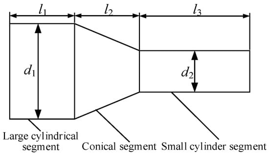
Figure 1.
Structural diagram of the composite horn.
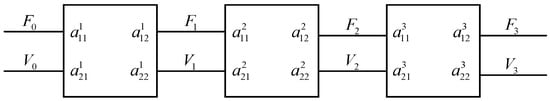
Figure 2.
Equivalent four-terminal network model.
Where F represents the elastic force on the horn section, V represents the vibration velocity; thus, the overall four-terminal network transmission matrix of the composite horn can be written as:
The left end face of the horn is defined as the pitch face, and the right end face is defined as the free output end. Then the boundary conditions can be defined as:
According to the boundary conditions, Equation (3) can be acquired:
The four-end network transmission matrix of each segment was obtained according to the one-dimensional fluctuation equation of the longitudinal vibration rod based on the boundary conditions of forces and displacements []. The transmission matrix of the large cylindrical segment is given by:
The transmission matrix of the conical transition section can be written as:
Moreover, the transmission matrix of the small cylindrical segment can be expressed as follows:
where c = (E/ρ)0.5 is the propagation velocity of the sound wave in the horn; E represents the elastic modulus of the material; ρ is the density of the material; k = ω/c is the circular wave number; z = ρcs represents the acoustic impedance of the cross-section; s is the cross-sectional area. The horn was made from non-magnetic materials to prevent magnetic leakage from affecting performance. In this article, 316 stainless steel was selected as the material for the horn, with the related parameters shown in Table 1.

Table 1.
The size of the composite horn.
The relevant parameters in Table 1 are substituted into Formulas (3), (4), (5) and (6), respectively, and then obtained
2.1.2. Modal Analysis
The mode shapes of the composite horn from 18 kHz to 22 kHz were extracted, and the result is shown in Figure 3. In the first-order modal vibration mode, the radial vibration occurred in the small cylindrical section, and the radial displacement at the end was the largest. The two modal shapes (X and Y) corresponding to the second-order modal natural frequencies were the bending vibration, but the directions of bending vibration were different. The third-order modal vibration mode was the longitudinal vibration mode required for the design. The longitudinal vibration frequency was 20,540 Hz, which was close to the theoretical design value of 20 kHz, indicating that the structural design of the composite horn was reasonable.
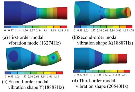
Figure 3.
Mode shape of the composite horn.
2.2. Design of Bending Vibration Disc
2.2.1. Design Theory
The tool head (the rotating wheel in the L-BCH) belonged to the thick disk, which cannot be calculated using the thin disk design theory. From the perspective of the acoustic application based on Mindlin plate theory, the vibration frequency equation of thick disk was derived, and the rotary wheel that met the requirements of bending vibration was designed []. In the free boundary condition, the bending moment and shear force at the disc boundary were zero. Then the bending vibration frequency equation of the disc is written as:
And
where R = t2/12, S = D/k2Gt, ; D = Eh3/12(1 − ε2) is the bending stiffness constant of the thick disk. R and S represent the effects of rotational inertia and transverse shear deformation in the thick disk, respectively. k2 = π/12; ε is the Poisson ratio, E is the elastic modulus, G = E/[2(1 + ε)] is the shear modulus; r, t, ρ, ω represent, respectively, the radius, thickness, density, angular frequency of the disk.
The radius and thickness of the disc were 40 mm and 20 mm, respectively. The disc’s material was the same as that of the composite horn, which was stainless steel 316 L, and the relevant material parameters are shown in Table 1. The first-order longitudinal vibration frequency of the disc was 20.228 kHz, which was calculated by bringing the above parameters into Equation (7). The modal analysis of the theoretically designed thick disc was carried out to extract the first four modal vibrations in the range of 10–30 kHz for the thick disc, and the results were shown in Figure 4. It is worth noting that each of the first three orders of vibrations generates bending vibrations differently. The second-order vibration mode was the bending mode of the disc along the axial direction, which is the required pattern for the design, with an inherent frequency of 20,443 kHz. The fourth-order vibration mode showed that the disc vibrated along the radial direction.
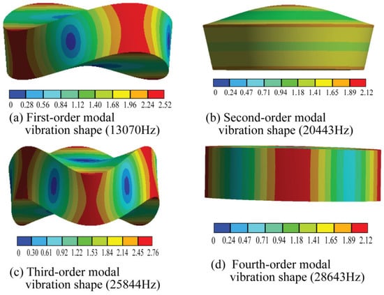
Figure 4.
Modal analysis of the disk.
2.2.2. Analysis of Rotating Wheel Model
Based on the modal analysis of the disc, the parameters in Table 2 are proposed to model the rotating wheel. The geometric model of the rotating wheel is shown in Figure 5.
Table 2.
Parameters of the spinning wheel mode.
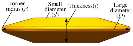
Figure 5.
The geometric model of the rotating wheel.
In a modal analysis of the rotating wheel, modal vibration was extracted for the frequency range of 15 kHz to 35 kHz. The result is shown in Figure 6, which shows that different degrees of bending vibration occur. In the first-order, third-order, and fourth-order vibration modes, different vibration degrees and vibration directions were experienced on the wheel edge. Such vibration modes did not meet the design requirements. However, in the second-order modal vibration, the vibration amplitude of the rim was consistent, and the vibration direction was uniform, which was the modal vibration required for spinning vibration machining. Its corresponding natural frequency was 20.697 kHz.
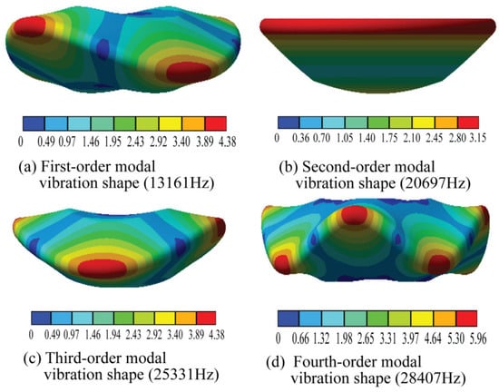
Figure 6.
Vibration mode of the rotating wheel.
2.3. Dynamic Simulation of the L-BCH
Finite element analysis was used to explore the effect of the geometry of the rotating wheel on the dynamic characteristics of the L-BCH. The 3D model was first imported into the workbench (Figure 7), and then meshes were created (Figure 8). The frequency range was set from 15 kHz to 25 kHz in solving the vibration modes. The finite element software could be used to obtain the inherent frequencies under longitudinal-bending vibration. Further, based on the modal analysis, a vibration displacement of 2 μm was applied to the left end of the composite horn. The number of analysis steps was set to 30; then, the harmonic response analysis of L-BCH was performed by the modal superposition method. Finally, the amplitude-frequency response curve of L-BCH was obtained, allowing the amplitude of the wheel edge under longitudinal bending vibration mode to be determined.
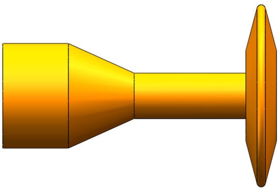
Figure 7.
Model of the L-BCH.
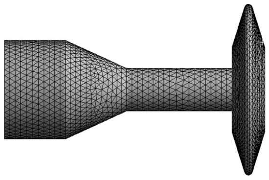
Figure 8.
Meshing division of the L-BCH.
2.3.1. The Influence of the Rotating Wheel’s Thickness on the Dynamic Characteristics
When taking no other structural parameters into account, the thickness of the spinning wheel was taken as 13 mm, 14 mm, 15 mm, 16 mm, 17 mm, 18 mm, and 19 mm, respectively. Figure 9 shows the modal analysis and harmonic response analysis of the L-BCH. As the thickness of the spinning wheel increased, so did the L-BCH natural frequency. In contrast, the amplitude of the wheel’s rim gradually decreased as its thickness increased. However, the rate of amplitude changed with thickness decreases. Thus, the thicker a spinning wheel was, the less impact it had on amplitude.
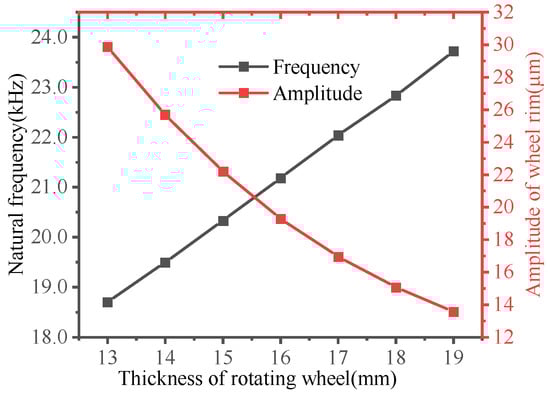
Figure 9.
The influence of thickness on the dynamic characteristics of the UL-BCH.
2.3.2. The Influence of the Spinning Wheel’s Large Diameter on the Dynamic Characteristics
The diameter of the rotary wheel was taken to be 74 mm, 76 mm, 78 mm, 80 mm, 82 mm, 84 mm, and 86 mm to obtain the relationship between the diameter of the rotary wheel and the dynamic characteristics of the L-BCH. Analyses were carried out on the L-BCH in modal analysis and harmonic response analysis. The results are presented in Figure 10. The natural frequency of the longitudinal-bending vibration mode of the L-BCH decreased gradually with the increasing diameter of the wheel. However, the amplitude of the wheel rim increased gradually. Therefore, we can conclude that the L-BCH’s natural frequency and amplitude were influenced oppositely by the large diameter and thickness of the rotating wheel.
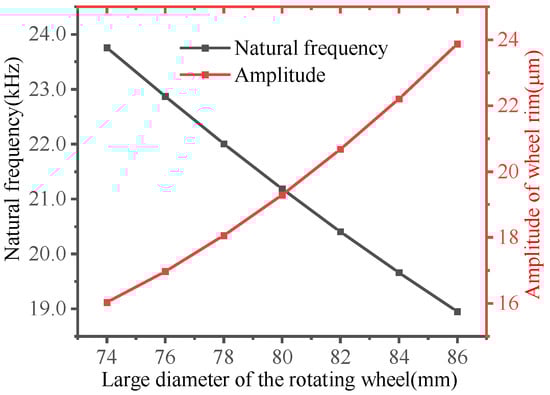
Figure 10.
Influence of spinning wheel’s large diameter on dynamic characteristics.
2.3.3. Influence of the Spinning Wheel’s Small Diameter on Dynamic Characteristics
To obtain the relationship between the small diameter of the rotary wheel and the dynamic characteristics of the L-BCH, we determined that the small diameters of the rotary wheels were 26 mm, 28 mm, 30 mm, 32 mm, 34 mm, 36 mm, 38 mm, and 40 mm, respectively, so that we can obtain a fair comparison. Moreover, the modal analysis and the harmonic response analysis of the L-BCH were performed. The results are shown in Figure 11.
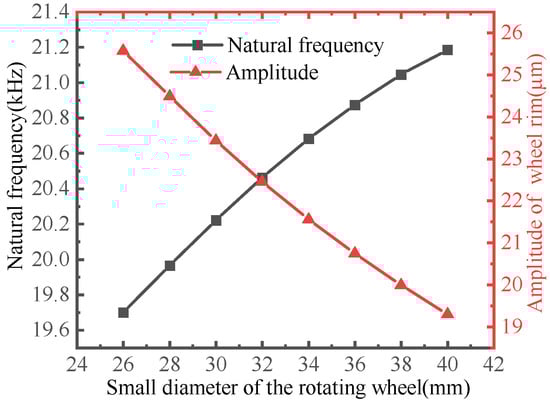
Figure 11.
Influence of spinning wheel’s small diameter on dynamic characteristics.
With the increase of the small diameter of the L-BCH, the material’s natural frequency increased gradually, while the degree of natural frequency change decreased. As the small diameter of the wheel increased, however, the amplitude of the rim of the wheel slowly decreased. Figure 9, Figure 10 and Figure 11 reveal that when the wheel’s small diameter increased from 26 mm to 40 mm, the natural frequency of the L-BCH increased from 19,702 Hz to 21,186 Hz, while the amplitude of the wheel rim decreased from 25.573 μm to 19.29 μm; as the rotational wheel’s thickness increased from 13 mm to 19 mm, the L-BCH’s natural frequency increased from 18,705 Hz to 23,721 Hz, while its amplitude decreased from 29.854 μm to 13.575 μm; by increasing the larger diameter of the rotating wheel from 74 mm to 86 mm, the L-BCH frequency decreased from 23,757 Hz to 18,951 Hz, whereas the amplitude of the wheel rim increased from 16.028 μm to 23.874 μm. According to the comparative analysis, the small diameter has a small effect on the natural frequency and amplitude of the L-BCH compared to the large diameter and thickness of the rotating wheel.
2.3.4. Influence of the Spinning Wheel’s Fillet Radius on Dynamic Characteristics
The fillet radius of the rotary wheel was taken to be 0.5 mm, 0.75 mm, 1 mm, 1.25 mm, 1.5 mm, 1.75 mm, 2 mm, 2.25 mm, 2.75 mm, and 3 mm, respectively, to obtain the relationship between the radius of the rotary wheel and the dynamic characteristics of the L-BCH. An analysis of the modal response and harmonic response of the L-BCH follows. The results are shown in Figure 12.
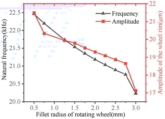
Figure 12.
Influence of spinning wheel fillet radius on dynamic characteristics.
It is evident in Figure 12 that both the natural frequency and amplitude decreased with increasing the rotating wheel fillet radius. The natural frequency of the longitudinal-bending vibration mode decreased from 22,463 Hz to 20,229 Hz as the radius of the fillet increased from 0.5 mm to 3 mm, and the amplitude of the wheel rim decreased from 21.494 μm to 17.121 μm. Compared with other structural parameters of the rotating wheel, the radius of the roller fillet had less influence on the amplitude of the wheel rim.
2.4. Determination of Structural Parameters of the L-BCH
According to the simulations above, the rotating wheel structural parameters have a varying degree of influence on the intrinsic frequency and amplitude of the L-BCH. In this article, the designed L-BCH was about 20 kHz intrinsic frequency. Meanwhile, due to the large mass of the rotating wheel, the design should minimize the mass and still meet the design requirements, such as reducing the amplicon impedance. Additionally, a 7 mm thick flange needed to be added to the left face of the L-BCH to meet the requirements for assembly with the ultrasound transducer. The optimized L-BCH’s structural parameters are presented in Table 3.
Table 3.
Structural parameters of the optimized L-BCH.
The modal analysis and harmonic response analysis of the optimized L-BCH was performed. The modal analysis was shown in Figure 13. Harmonic response analysis was conducted from 18,000 Hz to 22,000 Hz at a step of 100 Hz. In Figure 14, the amplitude-frequency response curve of the optimized L-BCH was plotted.
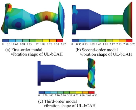
Figure 13.
Modal analysis of the optimized structure.
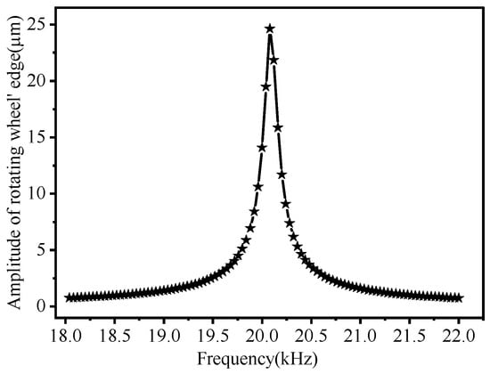
Figure 14.
Amplitude-frequency characteristic curve of the optimized structure.
Results of the analysis indicated that the second-order vibration mode of the optimized L-BCH was required for the design; 20,069 Hz was the natural frequency of the second-order longitudinal vibration mode, which was very close to the theoretical value of 20 kHz. It indicates that the structural design of the horn was reasonable because the amplitude of the wheel rim reached a maximum of 24.627 μm at 20,069 Hz. An axial amplitude was extracted along with the axial direction of the horn, and a radial displacement was extracted along with the radial contour of the wheel. These results are shown in Figure 15 and Figure 16.
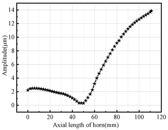
Figure 15.
Axial displacement of the horn.
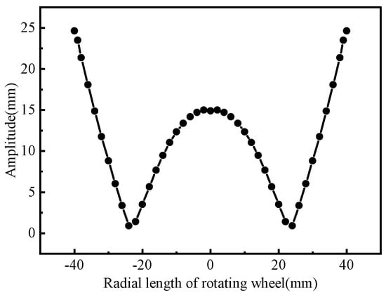
Figure 16.
Radial displacement of rotating wheel.
The rear face of the horn had an amplitude of 2.229 μm, while the front face had an amplitude of 15.079 μm, which indicated that the horn’s amplification factor was 6.76. An amplitude of 14.894 μm was measured at the center of the spinning wheel, while 24.627 μm was measured at the rim, indicating a magnification of 1.65, indicating the spinning wheel had extraordinary amplitude amplifying properties. In contrast, when the rotating wheel was 24 mm from the center, the amplitude was almost zero, showing that the rotating wheel had a pitch circle and that the pitch circle radius was 24 mm.
3. Result and Discussion
A prototype of the giant magnetostrictive transducer is made to verify the rationality of the structural design of the L-BCH, and the vibration test of the L-BCH is carried out. This prototype and the experimental equipment are shown in Figure 17 and Figure 18.
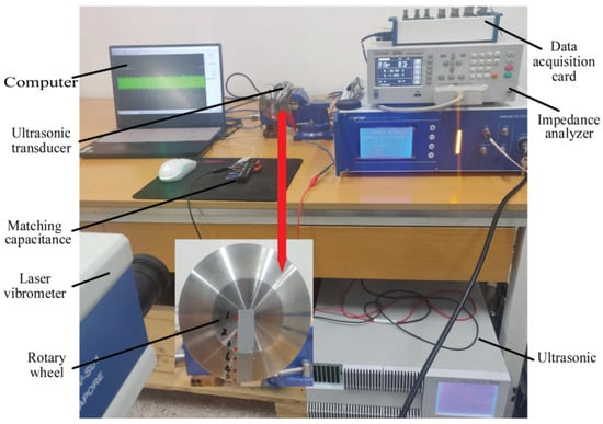
Figure 17.
Vibration test of the UL-bCH.
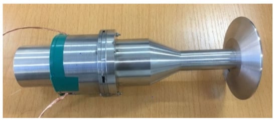
Figure 18.
The prototype of the giant magnetostrictive transducer.
Firstly, the transducer’s impedance is measured with an impedance analyzer, as shown in Figure 19, which shows that its resonant frequency is 20.51 kHz. After that, a laser vibrometer and an ultrasonic power supply are used to measure the vibration characteristics of this giant magnetostrictive transducer. The signal collected is fed back to the PC through the NI data acquisition card. Because of the symmetrical nature of the wheel, we chose six positions as the measuring points, which are 0, 10 mm, 20 mm, 30 mm, 40 mm, and 24 mm, respectively, from the center of the wheel and marked as 1, 2, 3, 4, 5, 6 one by one. A resonant state is achieved by adjusting the excitation frequency of the ultrasonic power supply. After that, the measured point’s amplitude is determined. The average value is calculated based on three measurements. When the excitation frequency of the ultrasonic power supply is 20,515.6Hz, it can be observed that the vibration velocity of the measured points on the spinning wheel approaches maximum. Hence, these results show that the L-BCH can resonate at a frequency close to the simulation resonant frequency, suggesting that it has been designed correctly. Figure 20 shows the amplitudes of six measured points at resonant frequencies. The comparison between simulation and experiment at each point is shown in Figure 21.
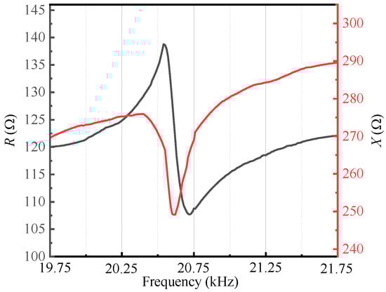
Figure 19.
Impedance curve of the giant magnetostrictive transducer.
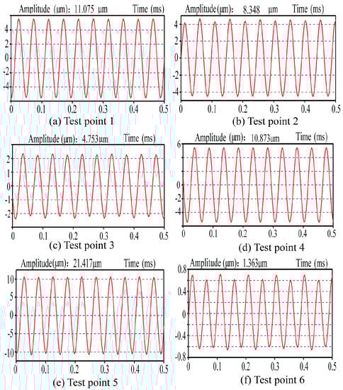
Figure 20.
Vibration test results of rotating wheel.
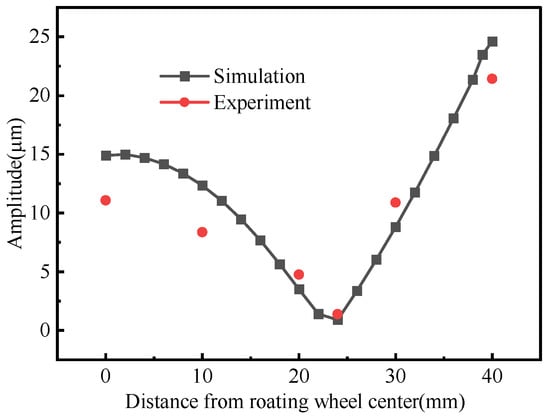
Figure 21.
Comparison of the simulation and experimental results.
Figure 20 shows that the amplitude at the center of the wheel (point 1) is 11.075 μm, while that at the wheel rim (point 5) is 21.417 μm, which indicates that the rotating wheel tool head enhances the amplitudes. A pitch circle can be seen as a fragile amplitude at the six-point, with a radius of about 24mm, which agrees with the simulation results. Figure 21 shows that simulation results are close to the experimental results, indicating that the design meets the ultrasonic horn. Because of the thermal losses of the transducer during operation, the amplitude of the measured point of the rotary wheel is smaller than that of the simulation result in the test., which led to a decrease in ultrasonic energy transmitted to the end of the horn, subsequently attenuating the amplitude of the rotary wheel tool head.
4. Conclusions
The design of L-BCH of a giant magnetostrictive for spinning ultrasonic vibration processing in this article is accomplished using theoretical design and finite element analysis, which focuses on how thickness, diameter, and corner radius affect the intrinsic frequency and amplitude of the transducer. In order to verify the design, a prototype of a giant magnetostrictive transducer is fabricated, and further vibration tests are conducted. Here are the research conclusions:
(1) Several physical and mechanical characteristics of the rotating wheel impact the dynamic characteristics of the L-BCH, including the large diameter, the small diameter, the thickness, and the fillet radius. One of the most significant aspects of the natural frequency and amplitude of the rotary wheel is significantly affected by the thickness of the rotary wheel. With regard to the practical engineering application of ultrasonic spinning, the effect can be enhanced by increasing the large diameter of the spinning wheel and reducing the thickness and small diameter correspondingly. However, this change also needs to consider the overall frequency characteristics.
(2) When the longitudinal-bending coupled vibration occurs on the rotating wheel, it results in a pitch circle, and the structure itself has the characteristic of amplifying the amplitude of the vibration too. The experimental data can provide theoretical guidance for using a high-power giant magnetostrictive transducer in spinning processing.
Author Contributions
Conceptualization, P.L.; methodology, Y.C.; software, W.L.; validation, W.L.; formal analysis, Y.C.; investigation, J.S., J.L. and K.W.; resources, P.L.; data curation, Y.C.; writing—original draft preparation, Y.C.; writing—review and editing, P.L.; visualization, W.L.; supervision, P.L.; project administration, P.L.; funding acquisition, P.L. All authors have read and agreed to the published version of the manuscript.
Funding
This study was funded by National Science Foundation of China (Grant No. 52075439) and Doctoral Innovation Fund of Xi’an University of Technology (Grant No. 252072104).
Institutional Review Board Statement
Not applicable.
Informed Consent Statement
Not applicable.
Data Availability Statement
Data is contained within the article as figures and tables.
Conflicts of Interest
The authors declare no conflict of interest.
References
- Wang, H.; Ning, F.; Li, Y.; Hu, Y.; Cong, W. Scratching-induced Surface Characteristics and Material Removal Mechanisms in Rotary Ultrasonic Surface Machining of CFRP. Ultrasonics 2019, 97, 19–28. [Google Scholar] [CrossRef] [PubMed]
- Gondo, S.; Arai, H. Effect and control of path parameters on thickness distribution of cylindrical cups formed via multi-pass conventional spinning. J. Intell. Manuf. 2022, 33, 617–635. [Google Scholar] [CrossRef]
- Trzepiecinski, T. Recent Developments and Trends in Sheet Metal Forming. Metals 2020, 10, 779. [Google Scholar] [CrossRef]
- Luo, W.; Chen, F.; Xu, B.B.; Yang, Z.J.; Guo, Y.M.; Lu, B.; Huang, T. Study on compound spinning technology of large thin-walled parts with ring inner ribs and curvilinear generatrix. Int. J. Adv. Manuf. Technol. 2018, 98, 1199–1216. [Google Scholar] [CrossRef]
- Wu, H.; Xu, W.; Shan, D.; Jin, B.C. Mechanism of increasing spinnability by multi-pass spinning forming—Analysis of damage evolution using a modified GTN model. Int. J. Mech. Sci. 2019, 159, 1–19. [Google Scholar] [CrossRef]
- Wen, X.; Tan, J.P.; Li, X.H. Optimization of spinning process parameters for the large-diameter thin-walled cylinder based on the drum shape. Int. J. Adv. Manuf. Technol. 2020, 108, 2315–2335. [Google Scholar] [CrossRef]
- Li, P.Y.; He, J.; Liu, Q.; Yang, M.S.; Wang, Q.D.; Yuan, Q.L.; Li, Y. Evaluation of forming forces in ultrasonic incremental sheet metal forming. Aerosp. Sci. Technol. 2017, 63, 132–139. [Google Scholar] [CrossRef] [Green Version]
- Sun, J.; Kang, R.; Qin, Y.; Wang, Y.; Dong, Z. Simulated and Experimental Study on the Ultrasonic Cutting Mechanism of Aluminum Honeycomb by Disc Cutter. Compos. Struct. 2021, 275, 114431. [Google Scholar] [CrossRef]
- Lee, H.; Singh, R. Acoustic radiation from out-of-plane modes of an annular disk using thin and thick plate theories. J. Sound Vib. 2005, 282, 313–339. [Google Scholar] [CrossRef]
- Du, P.; Han, L.; Qiu, X.; Chen, W.; Deng, J.; Liu, Y.; Zhang, J. Development of a high-precision piezoelectric ultrasonic milling tool using longitudinal-bending hybrid transducer. Int. J. Mech. Sci. 2022, 222, 107239. [Google Scholar] [CrossRef]
- Liu, Y.X.; Wang, L.; Gu, Z.Z.; Quan, Q.Q.; Deng, J. Development of a Two-Dimensional Linear Piezoelectric Stepping Platform Using Longitudinal-Bending Hybrid Actuators. IEEE Trans. Ind. Electron. 2019, 66, 3030–3040. [Google Scholar] [CrossRef]
- Shen, Q.Q.; Liu, Y.X.; Wang, L.; Liu, J.K.; Li, K. A long stroke linear stepping piezoelectric actuator using two longitudinal bending hybrid transducers. Ceram. Int. 2018, 44, S104–S107. [Google Scholar] [CrossRef]
- Yang, X.; Liu, Y.; Chen, W.; Liu, J. Miniaturization of a longitudinal–bending hybrid linear ultrasonic motor. Ceram. Int. 2015, 41, S607–S611. [Google Scholar] [CrossRef]
- Liu, Y.; Yan, J.; Wang, L.; Chen, W. A Two-DOF Ultrasonic Motor Using a Longitudinal–Bending Hybrid Sandwich Transducer. IEEE Trans. Ind. Electron. 2019, 66, 3041–3050. [Google Scholar] [CrossRef]
- Narayanan, M.M.; Arjun, V.; Kumar, A.; Mukhopadhyay, C.K. Development of In-bore Magnetostrictive Transducer for Ultrasonic Guided Wave based-inspection of Steam Generator Tubes of PFBR. Ultrasonics 2020, 106, 106148. [Google Scholar] [CrossRef] [PubMed]
- Fang, S.; Zhang, Q.; Zhao, H.; Yu, J.; Chu, Y. The Design of Rare-Earth Giant Magnetostrictive Ultrasonic Transducer and Experimental Study on Its Application of Ultrasonic Surface Strengthening. Micromachines 2018, 9, 98. [Google Scholar] [CrossRef] [PubMed] [Green Version]
- Ma, K.; Wang, J.; Zhang, J.; Feng, P.; Yu, D.; Ahmad, S. A highly temperature-stable and complete-resonance rotary giant magnetostrictive ultrasonic system. Int. J. Mech. Sci. 2022, 214, 106927. [Google Scholar] [CrossRef]
- Senjanovic, I.; Hadzic, N.; Vladimir, N.; Cho, D.S. Natural vibrations of thick circular plate based on the modified Mindlin theory. Arch. Mech. 2014, 66, 389–409. [Google Scholar]
- Lezgy-Nazargah, M. A high-performance parametrized mixed finite element model for bending and vibration analyses of thick plates. Acta Mech. 2016, 227, 3429–3450. [Google Scholar] [CrossRef]
- Farahmand, H. Analytical solutions of bending and free vibration of moderately thick micro-plate via two-variable strain gradient theory. J. Braz. Soc. Mech. Sci. Eng. 2020, 42, 251. [Google Scholar] [CrossRef]
- Usarov, D.; Turajonov, K.; Khamidov, S. Simulation of free vibrations of a thick plate without simplifying hypotheses. J. Phys. Conf. Ser. 2019, 1425, 012115. [Google Scholar] [CrossRef]
- Niu, Y.; Jiao, F.; Li, J.; Zhang, J.F. Study on the Effect of Vibration Amplitude in Two-Dimension Ultrasonic Vibration Cutting. Adv. Mater. Res. 2014, 1027, 131–135. [Google Scholar] [CrossRef]
- Niu, Y.; Jiao, F.; Tong, J.L.; Li, J.; Zhang, J.F. Research on Vibration Characteristics of Horn with Longitudinal Bending Vibration. Appl. Mech. Mater. 2014, 551, 121–126. [Google Scholar] [CrossRef]
- Shahid, M.B.; Jung, J.Y.; Park, D.S. Finite element analysis coupled artificial neural network approach to design the longitudinal-torsional mode ultrasonic welding horn. Int. J. Adv. Manuf. Technol. 2020, 107, 2731–2743. [Google Scholar] [CrossRef]
- Chen, T.; Liu, S.; Liu, W.; Wu, C. Study on a longitudinal-torsional ultrasonic vibration system with diagonal slits. Adv. Mech. Eng. 2017, 9, 168781401770634. [Google Scholar] [CrossRef]
- Li, P.Y.; Liu, Q.; Li, S.J.; Wang, Q.D.; Zhang, D.Y.; Li, Y. Design and numerical simulation of novel giant magnetostrictive ultrasonic transducer. Results Phys. 2017, 7, 3946–3954. [Google Scholar] [CrossRef]
- Chiu, Y.; Li, X.; Yu, G.; Yang, C.; Pan, J.; Chen, C. Research on effect of rings on coupling vibration in a rigid-disk rotor. J. Mech. Sci. Technol. 2020, 34, 521–530. [Google Scholar] [CrossRef]
Publisher’s Note: MDPI stays neutral with regard to jurisdictional claims in published maps and institutional affiliations. |
© 2022 by the authors. Licensee MDPI, Basel, Switzerland. This article is an open access article distributed under the terms and conditions of the Creative Commons Attribution (CC BY) license (https://creativecommons.org/licenses/by/4.0/).