Article

An Inverse Dynamics-Based Control Approach for Compliant Control of Pneumatic Artificial Muscles

by
Cabbar Veysel Baysal
Biomedical Engineering Department, Cukurova University, Adana 01330, Turkey
Actuators 2022, 11(4), 111; https://doi.org/10.3390/act11040111
Submission received: 7 March 2022 / Revised: 30 March 2022 / Accepted: 13 April 2022 / Published: 16 April 2022
(This article belongs to the Special Issue Pneumatic Muscle Actuators)

Abstract

:
Rehabilitation is an area of robotics in which human–robot collaboration occurs, requiring adaptation and compliance. Pneumatic artificial muscles (PAM) are soft actuators that have built-in compliance making them usable for rehabilitation robots. Conversely, compliance arises from nonlinear characteristics and generates obstructions in modeling and controlling actions. It is a critical issue limiting the use of PAM. In this work, multi-input single-output (MISO) inverse modeling and inverse dynamics model learning approaches are combined to obtain a novel nonlinear adaptive control scheme for single PAM-actuated 1-DoF rehabilitation devices, for instance, continuous passive motion (CPM) devices. The objective of the proposed system is to bring an alternative solution to the compliant operation of PAM while performing exercise trajectories, to satisfy requirements such as larger range of motion (ROM) and adaptability to external load impedance variations. The control system combines the operation of a nonlinear autoregressive network with exogenous inputs (NARX)-based inverse dynamics estimator used as a global range controller and cascade PIDs for local position and pressure loops. Implementation results demonstrated the efficacy of the introduced method in terms of compliant operation for dynamic external load variations as well as a stable operation in case of impulsive disturbances. To summarize, a simple but efficient method is illustrated to facilitate the common use of PAM.

1. Introduction

In recent years, advanced robotic technology has been applied for the rehabilitation of patients with stroke, neural diseases, and traumatic injuries. A recent review of rehabilitation robots and devices is illustrated in [1,2].
In rehabilitation therapies, repetitive and progressive functional training exercises are performed to gain motor abilities recovery and reconstruction of neuroplasticity [3]. Rehabilitation robots have been employed for the delivery of active-assistive, active-resistive, passive, and adaptive exercises of both upper and lower extremities. Comprehensive reviews of the robotic rehabilitation devices classified according to extremities can be found in previous works [4,5,6].
Rehabilitation is an area of robotics in which human–robot collaboration occurs. Actuator adaptability, inherent compliance, comfort, safety, versatility, and adaptability to individuals are the typical issues to be resolved. To bring advancements to the main issues for rehabilitation devices, different approaches have been developed based on actuator technologies and control system design points.
Soft actuators in rehabilitation devices are preferred due to inherent compliance and high force weight ratio, which is illustrated and criticized in [7]. Soft actuators can be easily integrated with rehabilitation devices. Among the soft actuators, pneumatic artificial muscles are preferred in some rehabilitation devices because of their versatile installation and low maintenance requirements. They could be primarily operated without electrical signals where the applied device becomes electrically safe for human interaction and interference problems [8].
Pneumatic artificial muscle (PAM) is a mature soft actuator and has been developed for more than three decades and manufactured in mass production for general industrial automation [9]. The pneumatic artificial muscle (PAM) is a fiber woven rubber actuator that changes its active length when applied pressure changes. PAM could demonstrate similar behavior to the human muscle as compared to common actuators, for instance, motors, hydraulic, and pneumatic actuators. When pneumatic artificial muscles (PAM) are pressurized, they contract and generate force in a nonlinear manner of radial inflation in size and axial contraction that yields pulling forces. It has a little weight and a great power/weight ratio. Moreover, the PAM has built-in compliance that makes it a possible solution for exoskeletons and rehabilitation robots [10]. However, compliance arises from nonlinear characteristics and generates obstructions in modeling and controlling actions. It is a critical issue limiting the use of PAM. The dynamic characteristics of PAM arenonlinearity, hysteresis, and time-varying responses. Therefore, it becomes very challenging to model the dynamics and to operate with model-based controllers.
PAM is not widely implemented in general robotic applications because of its critical disadvantages, for instance, slow response and inherent nonlinear characteristics. On the contrary, the disadvantages considerable for robotic applications are not crucial for rehabilitation devices where soft actuation behavior is more important. Looking from that perspective, PAM could be a major actuator type for rehabilitation robots and devices.
In the literature, there are many projects which use PAM as the actuator for both upper and lower extremity rehabilitation devices. The reviews discussing recent mechanical structures and control strategies for the rehabilitation robots driven by pneumatic artificial muscles are given in [11,12]. Most of the implementations are either exoskeletons or robotic orthotic devices [13,14].In the majority of those devices, an antagonistic approach and a double-acting actuation are implemented similar to human musculoskeletal configuration.
In addition, there are also simpler applications such as robotic elbow orthoses, robotic knee orthoses, and continuous passive motion (CPM) exercise machines. Robotic orthoses and CPM devices are used for repetitive 1-DOF cyclic motions and are used for elbow, knee, and ankle rehabilitation to treat spasticity and contractures. In those applications, a single PAM is utilized as the actuator against gravitational forces. The examples are illustrated in [15,16,17,18,19]. In these configurations, counteraction is either supported by gravitational forces or opposing springs. In Figure 1, the simplified mechanism diagrams for the PAM-actuated elbow orthosis and the CPM device for knee rehabilitation are presented.
Many up-to-date, different control approaches have been used for PAM-actuated rehabilitation devices. The classical PID control is the most used method in combination with empirical models which are developed using geometrical and phenomenological models, based on the application design [20,21]. Empirical model-based compensators are used to enhance PID in [22]. PID is also enhanced with other techniques such gain scheduled PID in [23]. The nonlinear control methods such as the sliding mode are implemented in [24]. Adaptive control and model reference adaptive control methods (MRAC) are also implemented in [25]. A combination of fuzzy and neuro-fuzzy methods with PID, sliding mode, and adaptive control are widely used as compensators for nonlinear dynamics of PAM stated in terms of either phenomenological or empirical models. A hybrid adaptive control structure in which a conventional PD controller in the feedforward path combined with a fuzzy controller in the adaptation path is illustrated in [26]. An enhanced adaptive fuzzy sliding mode control approach, a combination of sliding mode and fuzzy rule-based control, is proposed in [27] using the Lyapunov stability theorem. An intelligent adaptive control algorithm is proposed in [28] where the adaptive learning is performed by a neural network that adjusts the gains of a fuzzy sliding mode controller (FSMC). A hybrid structure using a dynamical neural network (DNN) and PID controllers are proposed for position control, where a cost function optimized via a particle swarm optimization (PSO) algorithm is used to obtain controller parameters using a geometrical model [29].
Although there are plenty of previous applications of PAM in use with rehabilitation devices, there are still many issues to be resolved in controlling PAM. In model-based approaches, such as geometrical, empirical, and phenomenological models, the design is quite sensitive to parameter changes. Control approaches that used model-based methods did not obtain desired compliance due to the parametric errors between the models and actual PAM dynamics. Conversely, model-free approaches are developed as an approximation of PAM dynamics using AI-based techniques. More specifically, the developed approaches have the following drawbacks.
1.
In many applications, the controlled range of motion (ROM) is quite limited, for instance −20 to +20 degrees which is not enough for many rehabilitation exercises.
2.
Compliance with external forces and load variation is very specific to implementations.
3.
PAM behavior is estimated as direct input–output, single-input single-output (SISO) models in terms of pressure and force but muscle contraction length is interpreted in model parameter approximations.
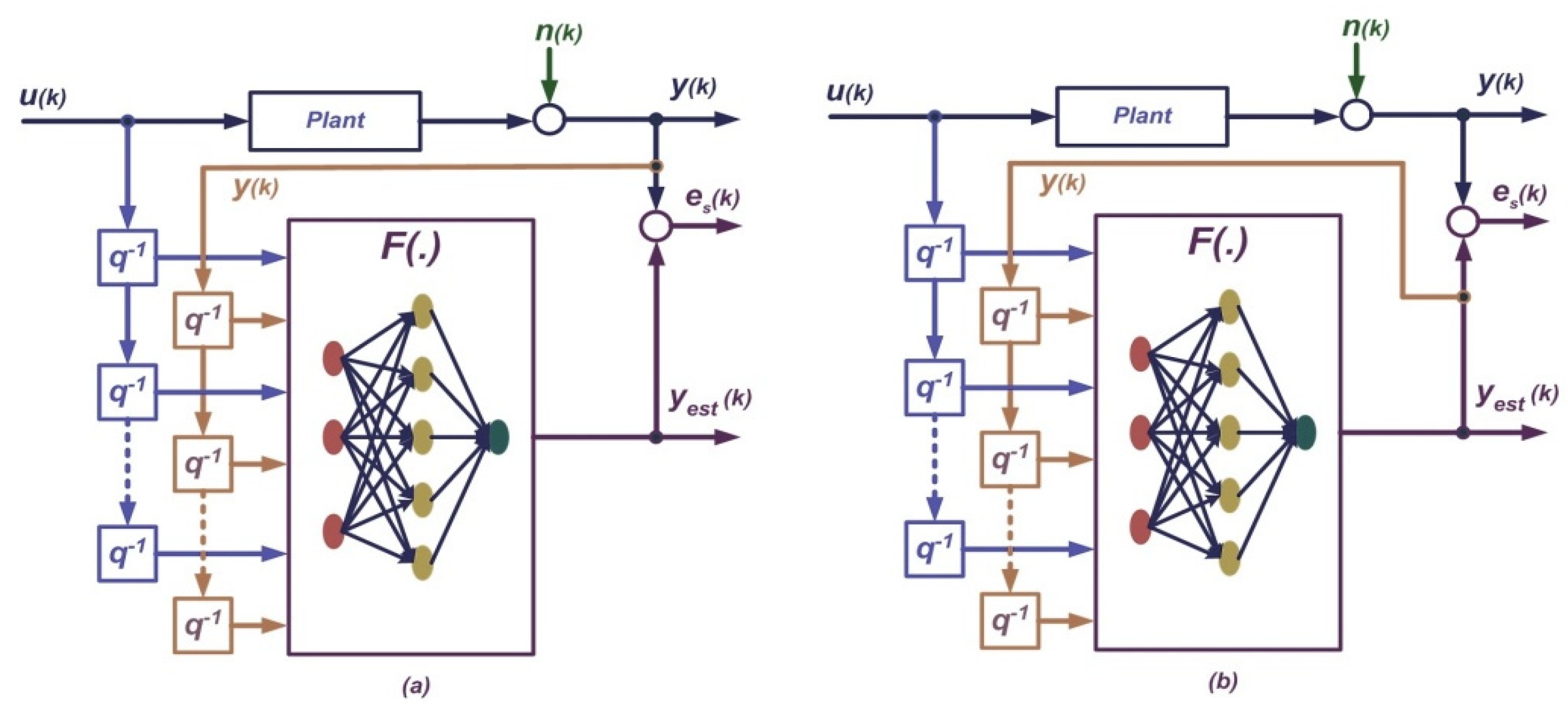
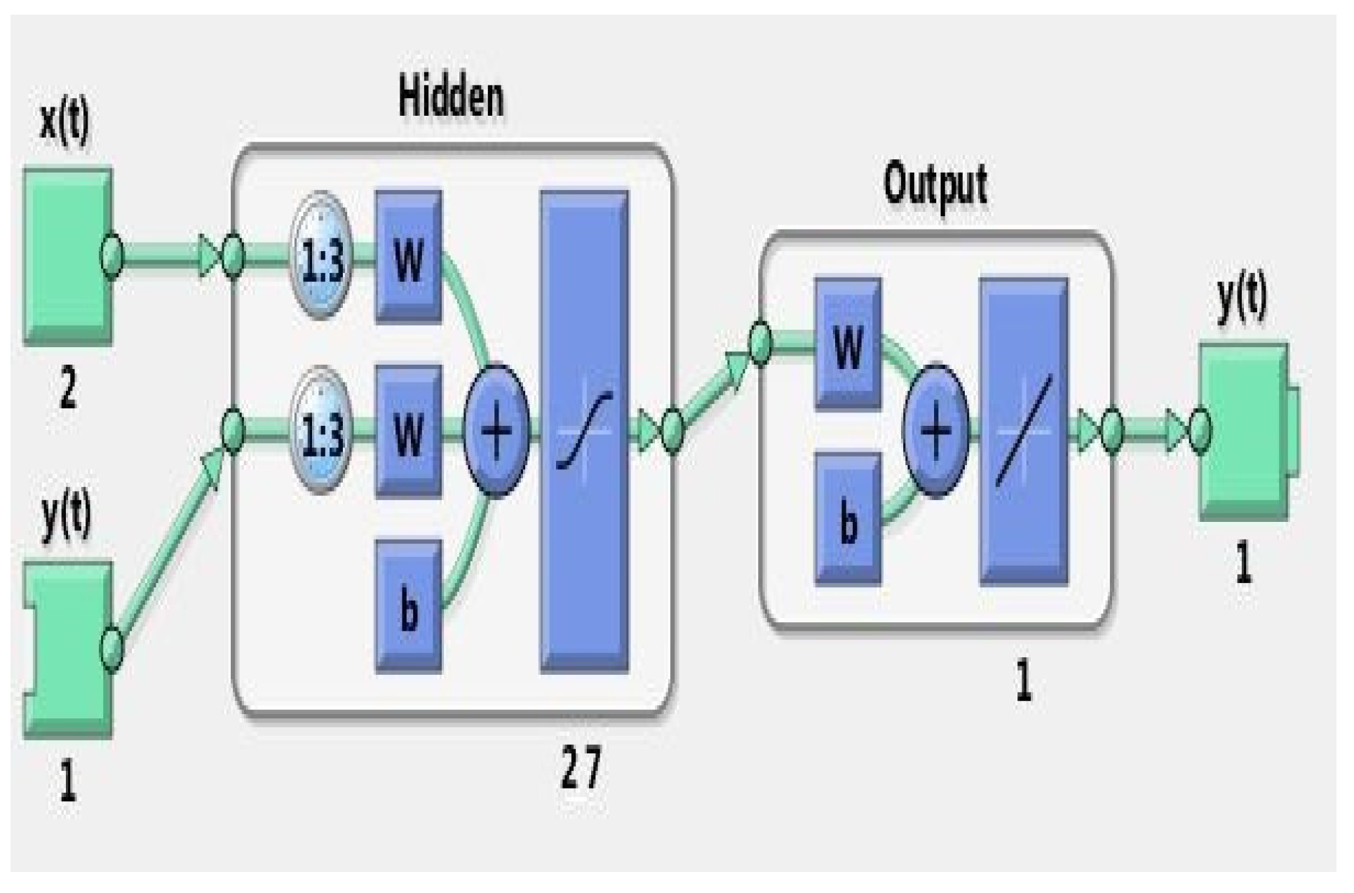
In this work, distinct from existing modeling works, the dynamic behavior of PAM has been estimated as an incorporated response to pressure input, resulting in simultaneous force and muscle length change. Hence, it is decided that standard SISO models with a direct input–output relation are not suitable for representing that behavior. Therefore, a multi-input single-output (MISO) inverse modeling approach given in [30] is implemented to utilize in control applications, MISO inverse model is developed by using an artificial neural network (ANN) structure utilizing the data produced during the PAM testbed experiments. In the approach, the MISO inverse model combines the desired actuator position with dynamic muscle length and simultaneous force generation demand yielding an output that is used as a low-level pressure set value for the PID pressure control loop. The approach is also distinct from [31], where a multi-input multi-output (MIMO) NARX-based inverse dynamic modeling of 2-DoF PAM-actuated robot arm is implemented. In that work, NARX-based inverse modeling uses joint angles as the inputs and end effector contact force and valve voltages as outputs, in order to model the complete robotic mechanism. On the contrary, the implemented approach in [30] is MISO and models the inverse dynamics of PAM solely by taking muscle dynamic length and muscle force as the inputs and muscle pressure as the output, which is being independent of the application mechanism or testbed. By this means, inverse PAM modeling could be transported to the control applications of different mechanisms.
Inverse dynamics model learning is initially proposed by Gomi and Kawato for impedance learning of 2-DoF robotic arm [32]. This approach is based on feedback error learning used for feedforward control of nonlinear dynamic systems. Further application of feedback error learning for nonlinear adaptive control is presented in [33] with Lyapunov stability analysis.
In this work, MISO inverse modeling and inverse dynamics model learning approaches are combined to obtain a novel nonlinear adaptive control scheme for single PAM-actuated rehabilitation devices such as robotic orthoses and CPM, to bring an alternative solution to compensate for the drawbacks of previous works. The MISO inverse dynamics model learning is implemented as an adaptive nonlinear feedback controller.
Employing the proposed approach, it is aimed to obtain:
1.
Larger controlled ROM up to 90 degrees.
2.
Better compliance to external forces and load variation.
3.
Estimation of PAM dynamic behavior, independent of application mechanism.
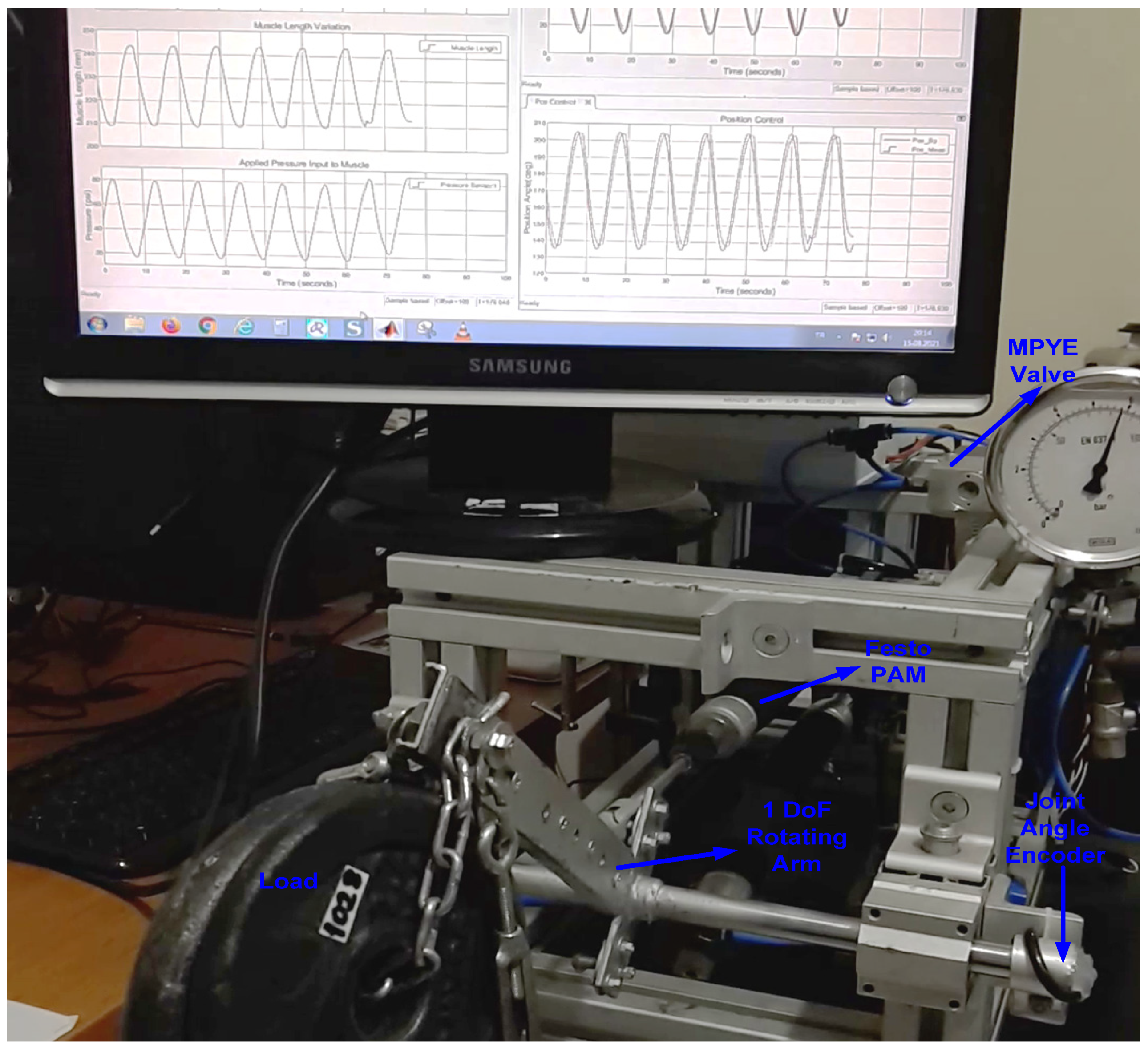
The proposed method is experimentally implemented using the testbed given in Figure 2, which is a 1-DoF rotary arm actuated by a single PAM. The testbed represents 1 DoF robotic orthoses or CPM devices running against the gravitational forces for repetitive exercise patterns.
Implementation details of our proposed method are presented in the next sections.
The rest of the paper is as follows: In Section 2, the implementation of the proposed MISO inverse modeling and nonlinear adaptive control method is given. Experimental testbed setup and data acquisition are also explained in detail. In Section 3, experimental results for different situations are presented. In Section 4, discussions are presented with future possibilities.

2. Materials and Methods

2.1. DynamicsBehaviorAnalysis for PAM

Investigation of a better control system design started with analyzing the dynamic behavior of PAM in our own designed testbed using Festo PAM [9].
PAM is an available off-the-shelf product supplied by Festo Company. The Festo muscle is constitutionally dissimilar to the generic McKibben muscles. The fiber of the Festo muscle is immersed into the rubber tube that offers simple usage and better hysteresis response and nonlinearity compared to generic muscles [9]. Due to constitutional peculiarity, Festo PAM has distinct characteristics in comparison to other existing PAM prototypes. In Figure 3, a DMPS20 series Festo fluidic muscle and its dynamic characteristics are illustrated.
In the initial stage of this work, the experiments are performed to evaluate to dynamical characteristics of Festo PAM, using a 1-DoF rotating arm hardware testbed designed and constructed in our lab, which is shown in Figure 2. The dynamic behavior of PAM has been observed during the experiments as an incorporated response to pressure input, resulting in simultaneous force and muscle length change. In the testbed experiments, data have been generated by applying different input pressure values and with different external loads to construct PAM dynamic operation data space. The block diagram of the implementation used for data preparation is given in Figure 4. Experimental data were attained by running a closed-loop PID pressure control in the testbed with a 0.05 Hz triangular reference signal, in the range of 10–680 kPa that is the operational range of Festo PAM. The pressure reference was chosen to gather stable characteristics of PAM. A load set composed of 28 different weight loads was used as effective load forces in the range of 20.6–1000 N. Each load item was connected one at a time to the testbed at rest and then the testbed runs with triangular pressure reference.
During each run, the data vector y(k) which is composed of the measured total force, load arm angle, estimated muscle length, and applied pressure was recorded with a sampling index in MATLAB. This operation was repeated for all load items.
In data acquisition, sensor data from analog signal amplifiers were fed into 12-bit ADCs of microcontroller unit with 10 ms sampling time Ts. It is important to express that in data acquisition, muscle full contraction (25%) and full extension (5%) ranges havebeen reached. The hardware structure of the testbed is illustrated in Figure 5. Explanations for components and range of physical quantities are given in Table 1 and Table 2 successively.
For the force application, loads hinged to the rotating arm are used. The total weight (Fw) is the sum of the applied load and load arm reflected weight. In order to estimate the net effective load force applied to PAM (FL), we use the moment calculation around the load arm rotation joint. Moments around the rotation joint link are equal to each other as given in (1), (2), and (3).
M L = M w
F L l 1 cos γ = F w l 2 cos γ
F L = F w K g
where load vertical inclination angle is given in
γ = θ m 90 °
For muscle length estimation, we use a rotational to translational motion conversion equation for the testbed given in
L m = L m i n + ( ( θ m θ m i n ) 2 π Ω ) / 360

2.2. Inverse Dynamics Estimator-Based Feedback Control Scheme

During the experimental analysis for PAM dynamic behavior, it has been observed that PAM suddenly changed its operating regimes whenever a change occurred either in external load forces or a change in contraction length of muscle due to external position disturbance. Since the applied pressure was the only input and the output response was the integrated form of generated force and muscle length change, an inverse dynamic modeling approach was used to obtain the nonlinear behavior of PAM itself, being independent of the application mechanism. In order to have compliance with the external load forces and positional changes, the actuator dynamics must be handled in a controlled manner and keeping it in a stable situation. Such a task requires the learning of the inverse dynamic model of PAM. Hence, MISO inverse modeling and inverse dynamics model learning approaches are combined to obtain a novel nonlinear adaptive control scheme for a single PAM-actuated 1 DoF rotating arm testbed. The proposed control system combines the operation of a nonlinear autoregressive network with exogenous inputs (NARX)-based MISO inverse dynamics estimator used for global range control and cascade PIDs for local position and pressure loops. The block diagram of the designed adaptive nonlinear feedback control system is given in Figure 6. Nomenclature for symbols used in the block diagram is given in Table 3.

2.3. NARX for Inverse Dynamics Estimation

Artificial neural networks have been used in implementations for the modeling and control of nonlinear dynamical systems. Amongst the neural networks, NARX is a type of recurrent neural network with dynamic behavior that has been developed from the ARX structure [34]. NARX can efficiently be used for modeling and controlling nonlinear systems. Bounded-input bounded-output (BIBO) stability of NARX is analyzed and demonstrated in [35]. There are adaptive nonlinear control applications that use NARX [36,37].
NARX neural network has two main architectures, parallel architecture (namely close-loop architecture) and series-parallel architecture (namely, open-loop), given in Figure 7. This study uses the open-loop architecture due to the nonlinear dynamics of the system under consideration. The NARX behavior could be mathematically modeled by Equation (6) which defines how a NARX network is used to estimate the y(k) value.
y e s t ( k ) = F [ y ( k ) , y ( k 1 ) , , y ( k m ) , u ( k ) , u ( k 1 ) , , u ( k m ) ]
Equation (6) makes use of the estimation output y(k) and the external input u(k), including previous values of both variables. The F(.), initially an unknown function, is an estimation function for the NARX feed-forward neural network (FFNN) block. It is formed in the training phase of the NARX in order to find a direct approximate mapping between input and output variables. As mentioned above, the NARX constitutes a model with nonlinear dynamic behavior that can approximate impending values of output using its previous estimated values and data from external inputs.

2.4. MISO NARX Structure for Inverse Dynamics Learning

Based on our inverse dynamics estimation approach, a MISO NARX has been designed. The details of the structure are given as follows:
MISO NARX has a FFNN structure for nonlinear estimation. Implemented MISO NARX block diagram is shown in Figure 8 and symbols are explained in Table 4. FFNN is basically a multilayer perceptron (MLP) network. MLP is a static neural network however when time-delay feedback from system dynamics makes it an externally recurrent dynamic network. In MLP, there are three layers, input, hidden, and output layers. The network output function is F(w,x) in terms of x and w. The w is the ordered weight vector and the input vector is x given by Equation (7).
x = [ x 1 , x 2 , , x m ] T
There are m nodes at input layer and n nodes at hidden layer with a single output node. Output of each hidden node is given in Equation (8)
λ j ( k ) = Ψ [ i = 1 m w j , i 1 x i ( k ) + b 1 ]
Output of MLP is given by Equation (9)
y 2 ( k ) = F ( w , x ) = Φ [ j = 1 n w o , j 2 λ j ( k ) + b 2 ]
where activation function for hidden layer is tansig() (hyperbolic tangent sigmoid)given in Equation (10) and it is purelin() (pure linear) for output layer given in Equation (11),
Ψ ( α ) = 1 e 2 α 1 + e 2 α
Φ ( α ) = α

2.5. Training Method for MISO NARX

The Levenberg–Marquardt algorithm is a method that is used for the problem of minimizing a nonlinear function [38]. The algorithm is fast and has a stable convergence and is widely used in the area of artificial neural networks. It is suitable for training small- and medium-sized networks. MISO NARX implementation of the Levenberg–Marquardt algorithm is the optimization of output function F(w) with respect to weights w. For the implementation, the cost function given in (12) is commonly used.
E ( w ) = 1 2 k = 1 N ( y 1 ( k ) y 2 ( k | w ) ) 2 = 1 2 e T e
where
e ( k ) = y 1 ( k ) y 2 ( k | w )
The vector y1 and y2 are column vectors of measured output and estimated MISO NARX output, respectively. Both vectors have a length of N, as data size. y2 is also a function of NARX parameter vector w. In order to minimize the cost function E(w), a gradient operator G is defined as follows:
G = E ( w ) w = e w E ( w ) e = J T e
where matrix J is defined as Jacobian matrix given as
J = e w T = e y 2 y 2 w T = y 2 w T
The second derivative of E(w) is called as Hessian matrix H given as,
H = 2 E ( w ) w 2 = ( E ( w ) / w ) w T = ( J T e ) w T
H = J T e w T + J T w T e = J T J + S e
after application of the Levenberg–Marquardt approximation given in [34],
H = J T J + μ I
is obtained and where I is identity matrix and μ is called combination coefficient which is always positive. The weight update rule of the Levenberg–Marquardt algorithm becomes as below:
w k + 1 = w k ( J k T J k + η I ) 1 J k e k
Indeed, the update rule is the derived from Gauss–Newton algorithm. In the learning process, Jacobian matrix J has been calculated and weight updates are performed as similar to error backpropagation (EBP) algorithms.

2.6. Software Implementation of MISO NARX

NARX Artificial Neural Network was implemented by using MATLAB ANN Toolbox. NARX-ANN was constructed with 1 hidden layer composed of 27 neurons. It was trained with the Levenberg–Marquardt algorithm. The structure of NARX-ANN is formed in an empirical manner. MATLAB implementation block diagram is given in Figure 9. The experimental data in terms of force, muscle length, and pressure that were previously collected for the dynamic behavior of PAM in the testbed have been used for training and testing NARX-ANN. The training and testing performance of ANN is given in Figure 10 and Figure 11. Regression results indicate that ANN is successfully trained and tested.

2.7. The Control System Implementation

The proposed control system in Section 2.2 whose block diagram is shown in Figure 6 is implemented in MATLAB/Simulink. A simplified Simulink block diagram of the implemented control system is illustrated in Figure 12. The control system is composed of cascaded position and pressure control loops operated by PIDs and the NARX-based MISO inverse dynamics estimator. The control system combines the operation of a NARX-based inverse dynamics estimator used as a global range controller and cascade PIDs for local position and pressure loops. The desired actuator position with dynamic muscle length and simultaneous force generation demand is fused by the MISO inverse model yielding the pressure set value for the PID pressure control loop.
The pressure loop PID controller is tuned using the Ziegler–Nichols reaction rate method. The PID parameters are estimated as Kp = 150, Ti = 0.24, Td = 0.06. After tuning pressure loop PID, step and sinusoidal tracking responses are obtained which is given in Figure 13. Position loop PID controller is tuned using the Ziegler–Nichols cyclic oscillation method. The PID parameters are estimated as Kp = 0.6, Ti = 0.05, Td = 0.01. Parameters were kept fixed during operations.
In this work, the proposed method is a kind of “Model-Free Control Approach”, and stability of the overall system is considered as bounded-input bounded-output (BIBO) stability instead of Lyapunov-based analyses. The BIBO stability of the overall system is demonstrated by experimental results in the following sections.

3. Results

In this work, the experimental results are presented in categories. The results are given in a format that is composed of force, muscle length variation, applied pressure, pressure control loop, and position control loop subsections in order to evaluate the performance of the designed control system. First, the results from regular trajectory tracking responses of the system that occurred under normal operating conditions are given where NARX estimation-based control is active. Next, the performance comparison results between NARX active and PID-only operation modes are explained. In addition, the results that occurred during the transition between NARX activation and deactivation modes are also given. Finally, results demonstrating the compliant control capability of the designed system are presented.

3.1. Regular Trajectory Tracking Results with NARX Estimation Active Control

In this section, a sample is given of the results obtained during regular trajectory tracking occurred under normal operating conditions with a fixed external load and when NARX estimation is active. In Figure 14, the control system response to 0.1 Hz sinusoidal trajectory tracking operation with 70 ROM is given. When subsections are inspected, pressure and muscle length variations are in accordance with reference values. However, an interesting situation is observed at the total force plot. In that plot, operation regions are marked with I, II, and III to explain dynamic behavior. For region I (F = 229.5 N), there is a movement of extension and for region II (F = 263.1), there is a movement of flexion wherein both regions the total forces are almost constant. This situation resembles isotonic contractions of human muscles. For region III (F = 315.7 N peak), there is a little flexion, but the total force increases resembling isometric contraction. The observed characteristics support that PAM mimics the behavior of human muscles by contracting and generating force.
In Figure 15, the control system response to a step reference trajectory tracking operation with 60° ROM is given. When subsections are inspected, pressure and muscle length variations are in accordance with reference values. However, in the total force plot, there are damped oscillations that occur due to motion stops affecting load arm dynamics. The controller responses indicated in this section demonstrate that the proposed control method is efficient for single-acting PAM cyclic motion devices.

3.2. Position Trajectory Tracking Responses at Different Frequencies

In this section, the results obtained during regular trajectory tracking with different frequencies under normal operating conditions are given. Results are obtained with a fixed external load and when NARX estimation is active. In Figure 16, the control system responses to sinusoidal trajectories with 0.1, 0.25 and 0.5 Hz. Tracking operation with 60–70° ROM are given. A step reference trajectory tracking operation with 60° ROM is also given. The results demonstrate that the control system successfully performs at different frequencies.
In Figure 17, position error graphics for the step response is given. For the step response, the steady-state position error is in the range of −0.52°…+1.62°, which is quite acceptable in 60–70° ROM. On the other hand, for sinusoidal trajectories, higher values of position errors are observed for 0.1 Hz, 0.25 Hz and 0.5 Hz, in the range of −5.5°…+3.5°, which is also quite acceptable in 60–70° ROM and the position errors are seen in Figure 18.

3.3. Performance Comparison Results: PID-Only versus NARX Estimation Active

In this section, the results for performance comparison between NARX active and PID-only operation modes are given while regular trajectory tracking under normal operating conditions with a fixed external load. In Figure 19, the control system responses to 0.25 Hz sinusoidal trajectory tracking operation are given. In part a, pressure control loop and position control loop responses are illustrated when only PID controllers are active. In part b, NARX estimation is active with PID controllers.
The results indicate that regular trajectory tracking could not be performed by cascaded PID-only control whereas PID controllers with NARX estimation could handle trajectory tracking. PID-only operation could reach 35° ROM although desired trajectory has a 60° ROM. On the other hand, NARX estimation could fulfill the duty with a 60° ROM. A similar situation is also observed when step reference trajectory tracking is given in Figure 20. Unbounded oscillations occurred in the PID-only pressure control loop which could even damage the testbed.

3.4. Results Occurred in Transition between NARX Deactivation and Reactivation Modes

In this section, the results for control system response during the transition between NARX deactivation and reactivation modes are given while regular trajectory tracking under normal operating conditions with a fixed external load. In Figure 21, the control system response to 0.25 Hz sinusoidal trajectory tracking operation is given, during deactivation and reactivation transition. It is observed that when NARX is deactivated (marked as X), there were large deviations in the trajectory tracking. However, when NARX is reactivated (marked as Y), it successfully estimates and quickly catches the desired trajectory. This behavior indicates that the designed control system can handle the transition processes successfully. In this result, stable characteristics of the designed control system could be observed. Even though the magnitude of desired input position trajectory varies during the transition, the output response of the system closely follows the input, as it followed pre-transition. The system also successfully follows the trajectory after the disruption. Hence, the balanced transition behavior and mode rate response of the system indicate the BIBO stability. The numerical values for critical points are given in Table 5.

3.5. Results Demonstrating Compliant Operation Capability of the System

In this section, results demonstrating compliant control capability of the designed control system are presented in two categories. In the first category, compliance capability to external load force change is demonstrated by load addition and removal to testbed lever arm while regular trajectory tracking occurred under normal operating conditions with different frequencies. In the second category, it is demonstrated by applying impulsive external forces to the testbed lever arm while regular trajectory tracking occurred under normal operating conditions with different frequencies.
In Figure 22, the control system response to 0.1 Hz sinusoidal trajectory tracking operation is given, during the external load addition (marked as X) and removal (marked as Y) process. It observed that the control system handles the external load force change without any significant change in trajectory tracking, by adjusting a proper pressure set point. This behavior indicates that the designed control system can handle operate in compliance with external load changes while keeping trajectory tracking. The numerical values for critical points are given in Table 6.
In Figure 23, dynamic external load addition and removal performance comparison results for 0.25 Hz sinusoidal reference position tracking is given for PID-only operation and NARX active operation responses, in order to demonstrate efficacy of the designed control system response.
In Figure 24, the control system response to external load force changes at0.5 Hz sinusoidal trajectory and step reference tracking is given. It is observed that the control system handles the external load force change without any significant change in trajectory tracking at different trajectory frequencies.
In Figure 25, the control system response to 0.1 Hz sinusoidal trajectory tracking is given, while random impulsive external forces are applied. Impulsive forces applied against the direction of motion are marked as A, C and the ones applied along the direction of motion are marked as B, D. It observed that the control system handles the impulsive external forces in both directions without any significant change in trajectory tracking, by adjusting a proper pressure set point. This behavior indicates that the designed control system can operate in compliance to sudden impulsive collisions while keeping trajectory tracking. The numerical values for critical points are given in Table 7.
In Figure 26, the control system response to random impulsive external forces is given while 0.25 Hz and 0.5 Hz sinusoidal trajectory tracking. It is observed that the control system handles random impulsive external force changes without any significant change in trajectory tracking at different trajectory frequencies.

4. Discussion

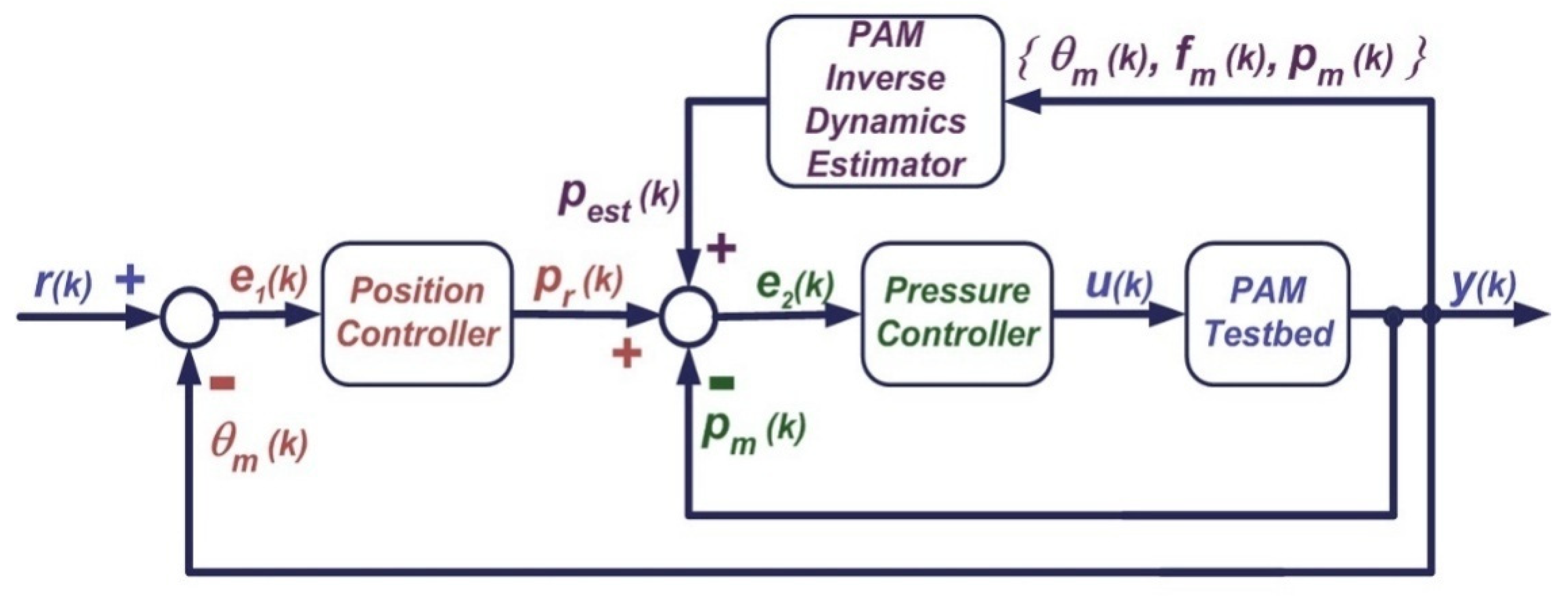
In this work, a novel control system is designed and experimentally implemented to bring an alternative solution to the compliant operation of PAM while performing exercise trajectories, to satisfy requirements such as larger ROM and adaptability to external load impedance variations. MISO inverse modelling and inverse dynamics model learning approaches are combined to obtain a novel nonlinear adaptive control scheme for single PAM-actuated 1-DOF rehabilitation devices, such as robotic knee orthoses, robotic elbow orthoses, and other continuous passive motion (CPM) devices. The control system combines the operation of a NARX-based inverse dynamics estimator used as a global range controller and cascade PIDs for local position and pressure control loops.
The control system is also distinct from other NARX-based inverse dynamic modeling approaches found in the literature. In [31,
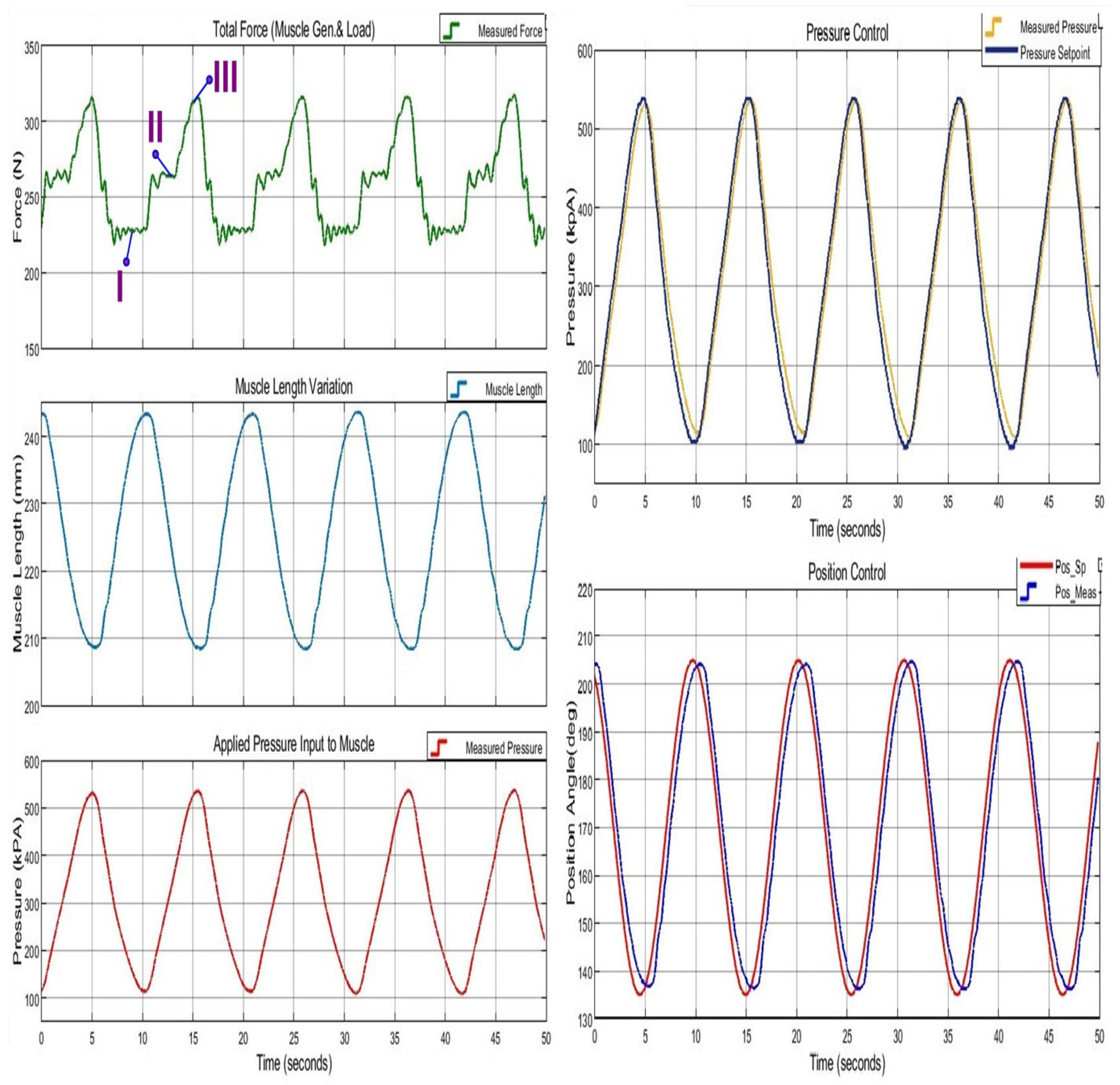
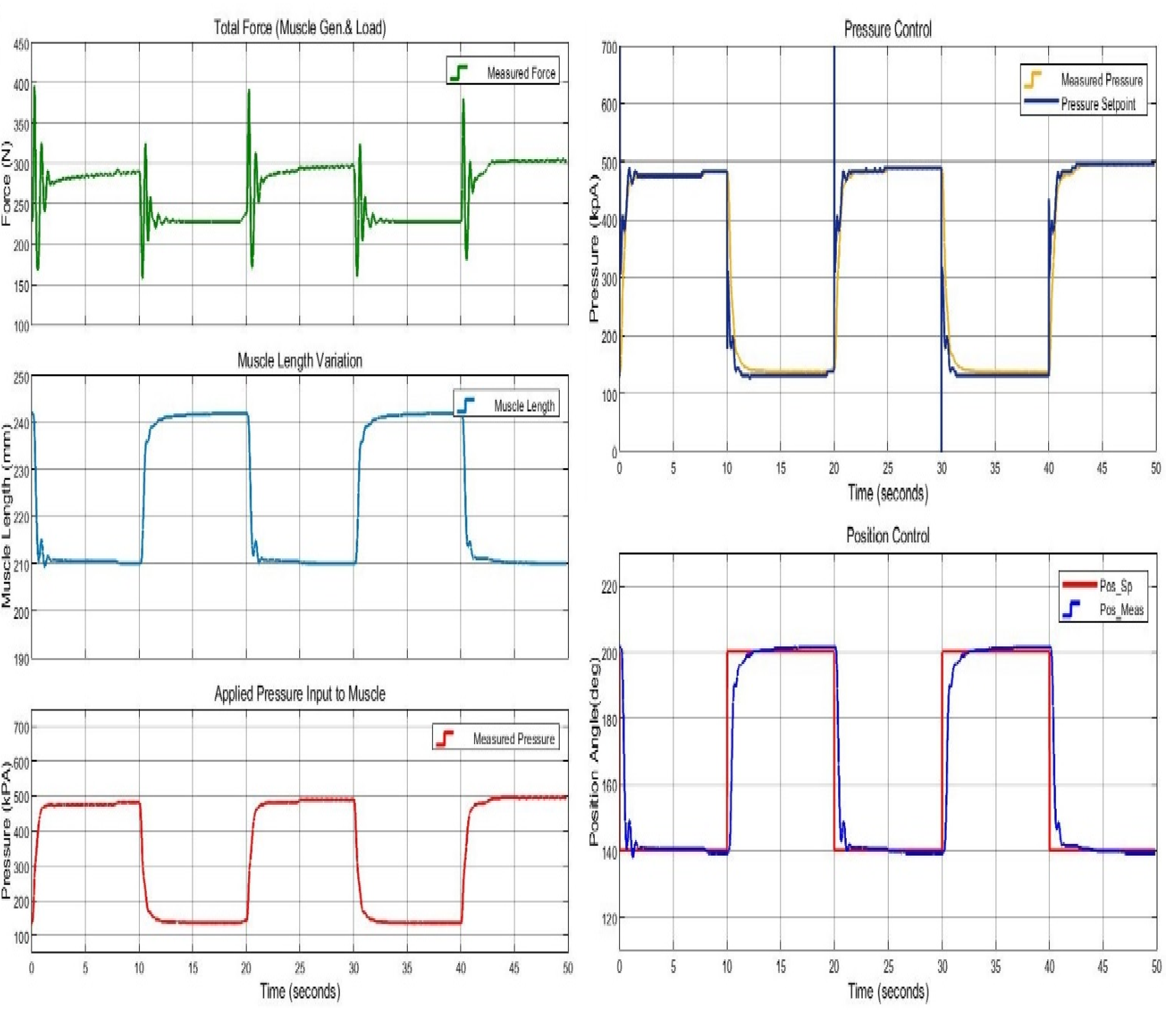
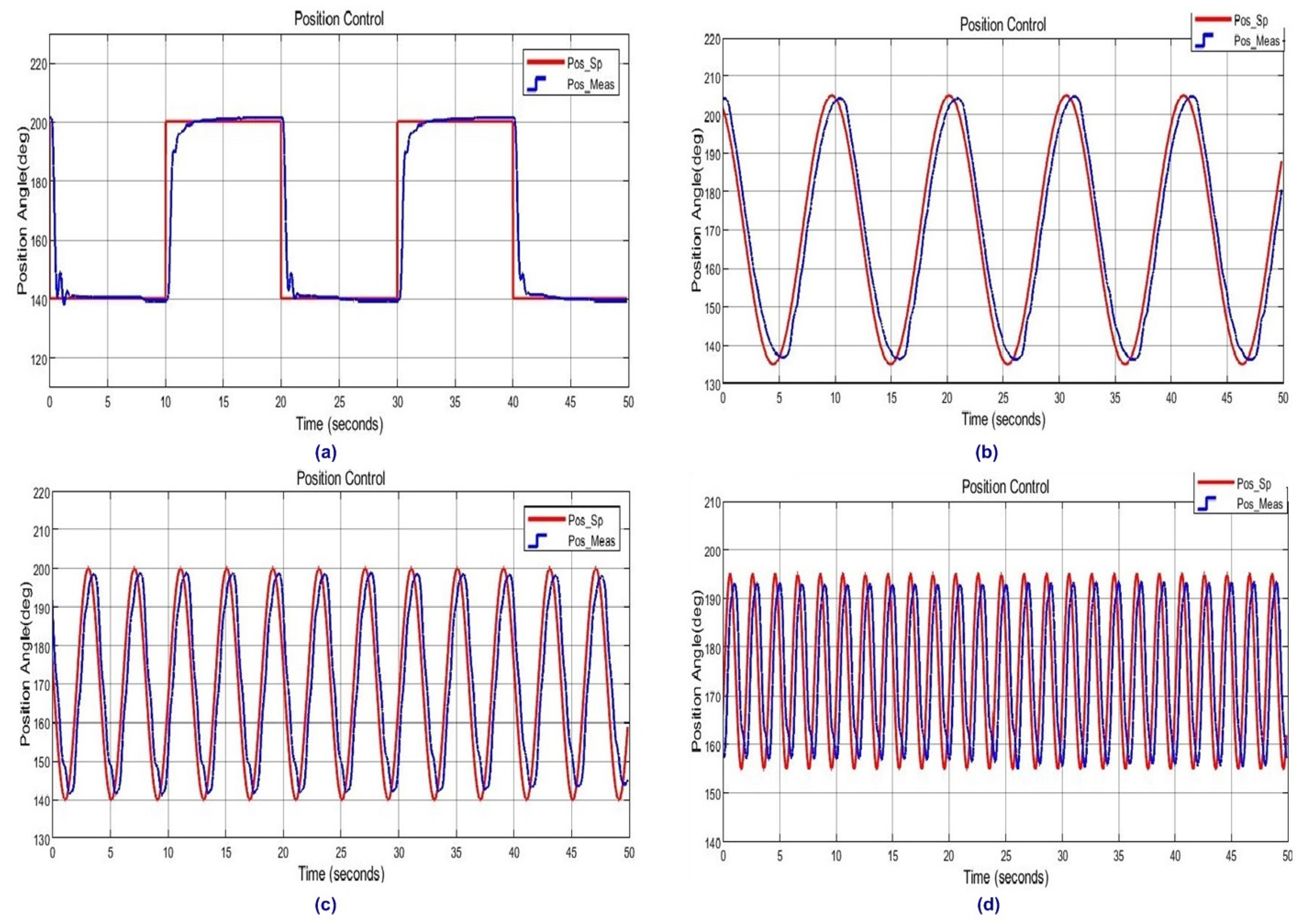
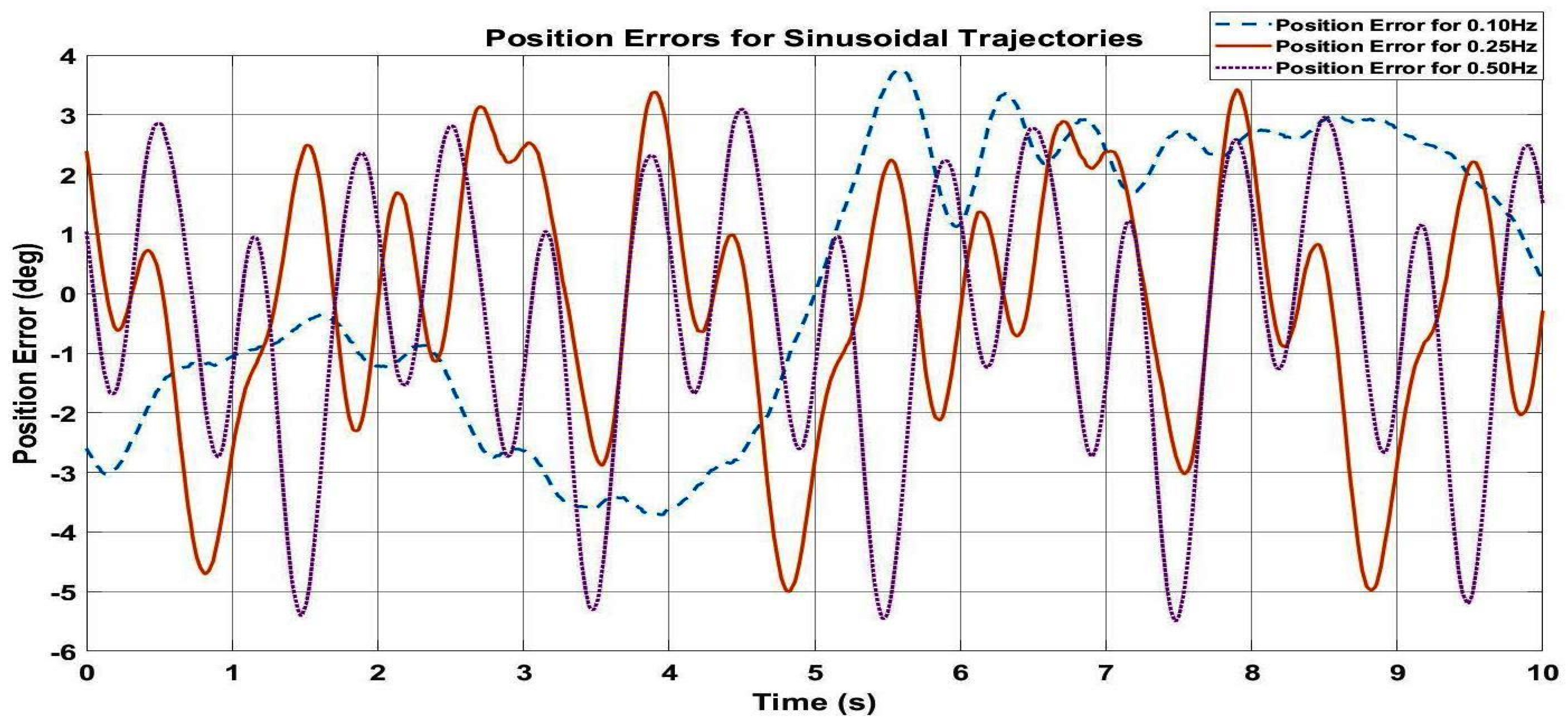
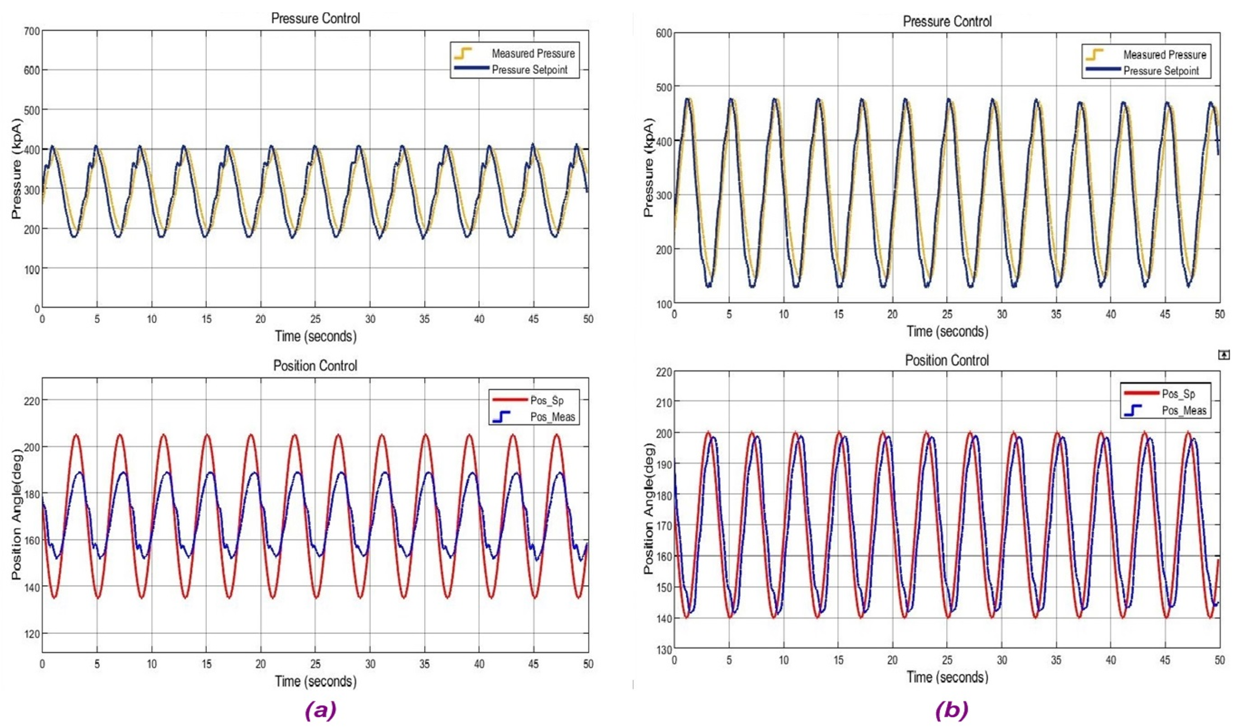
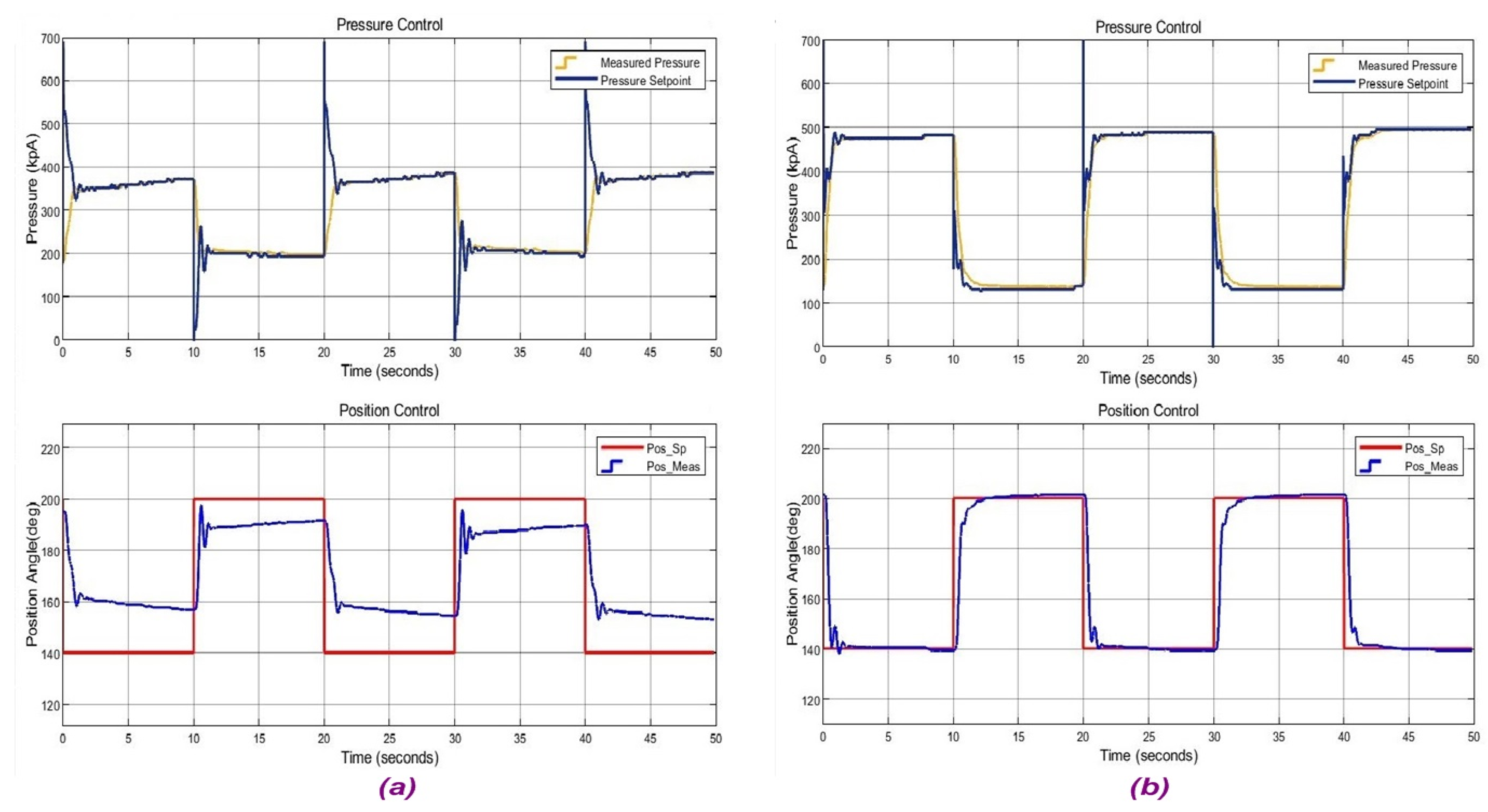
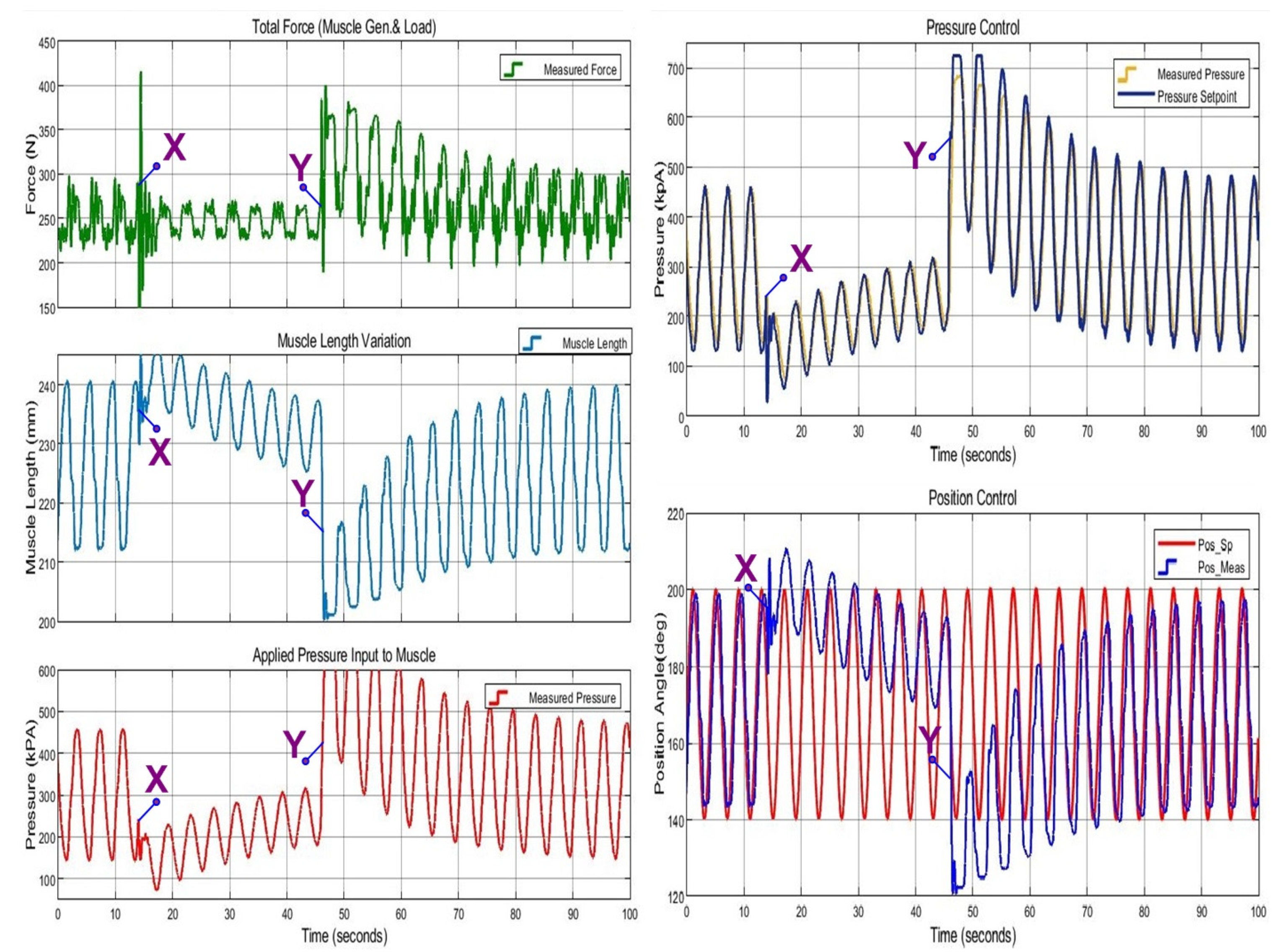
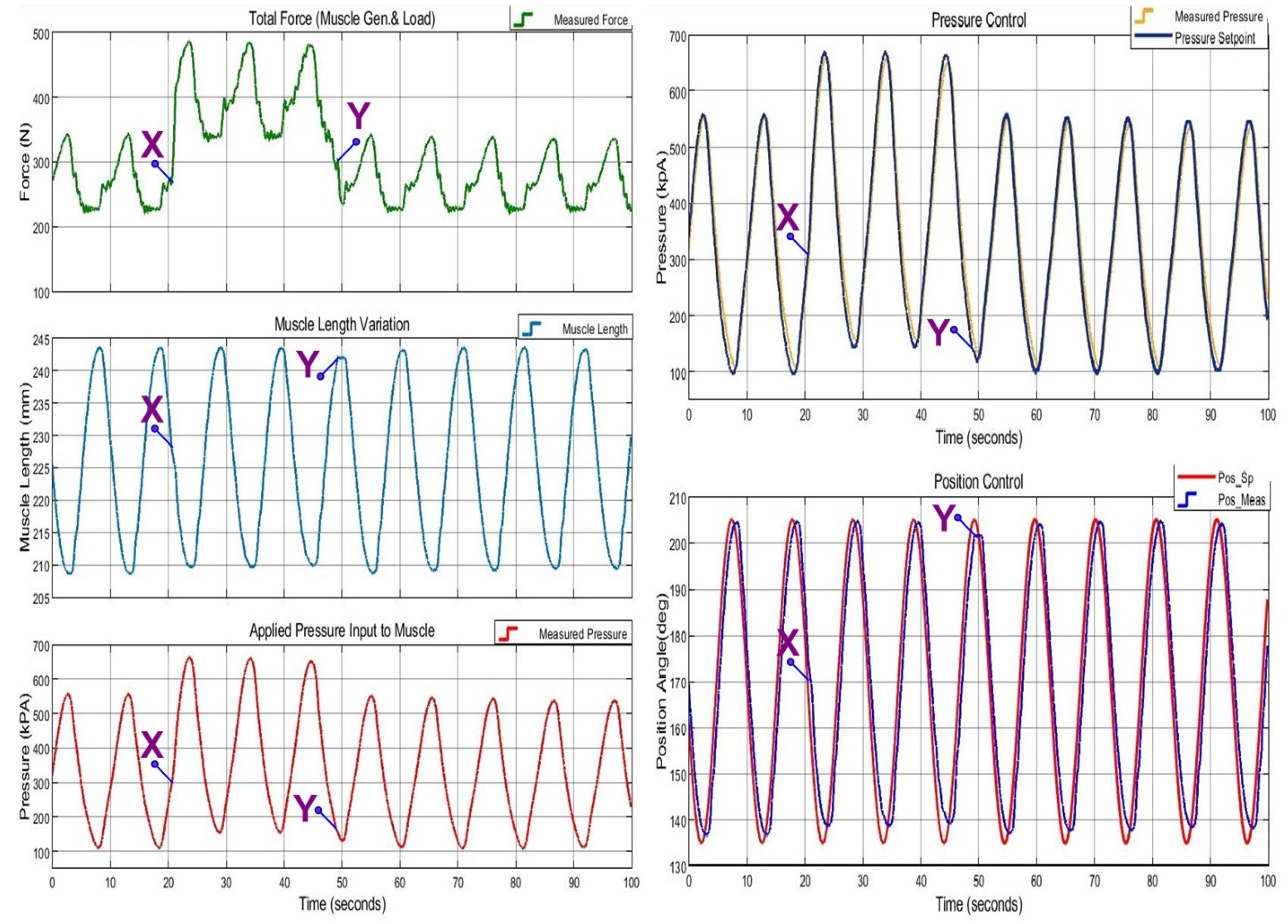
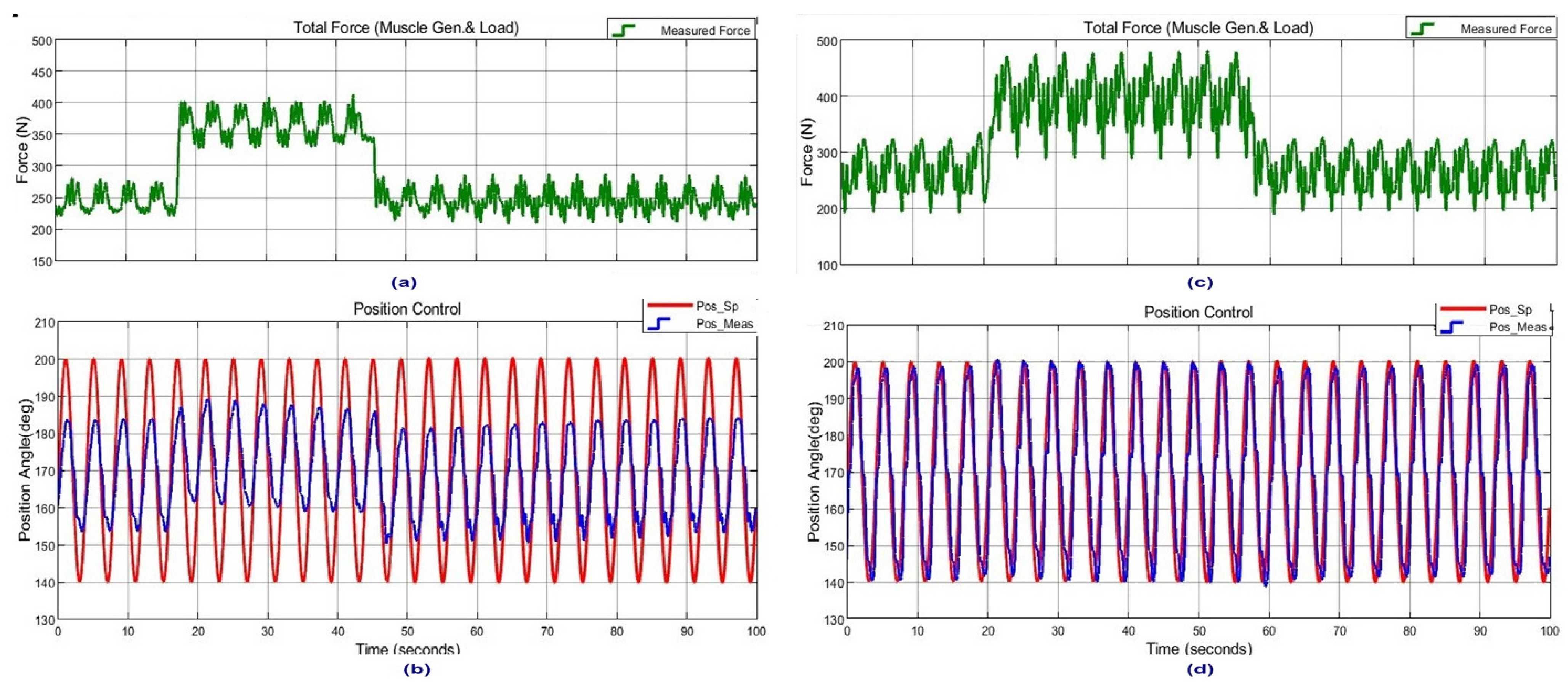
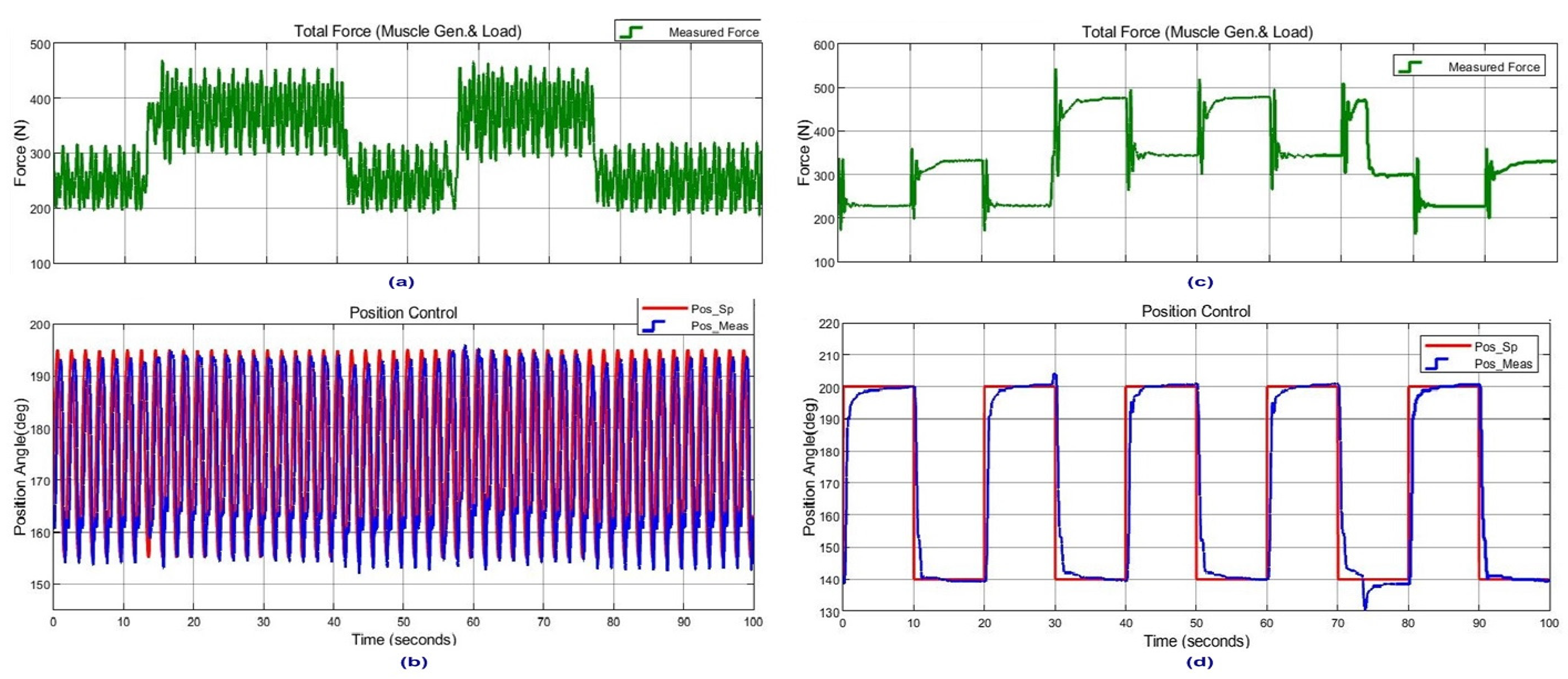
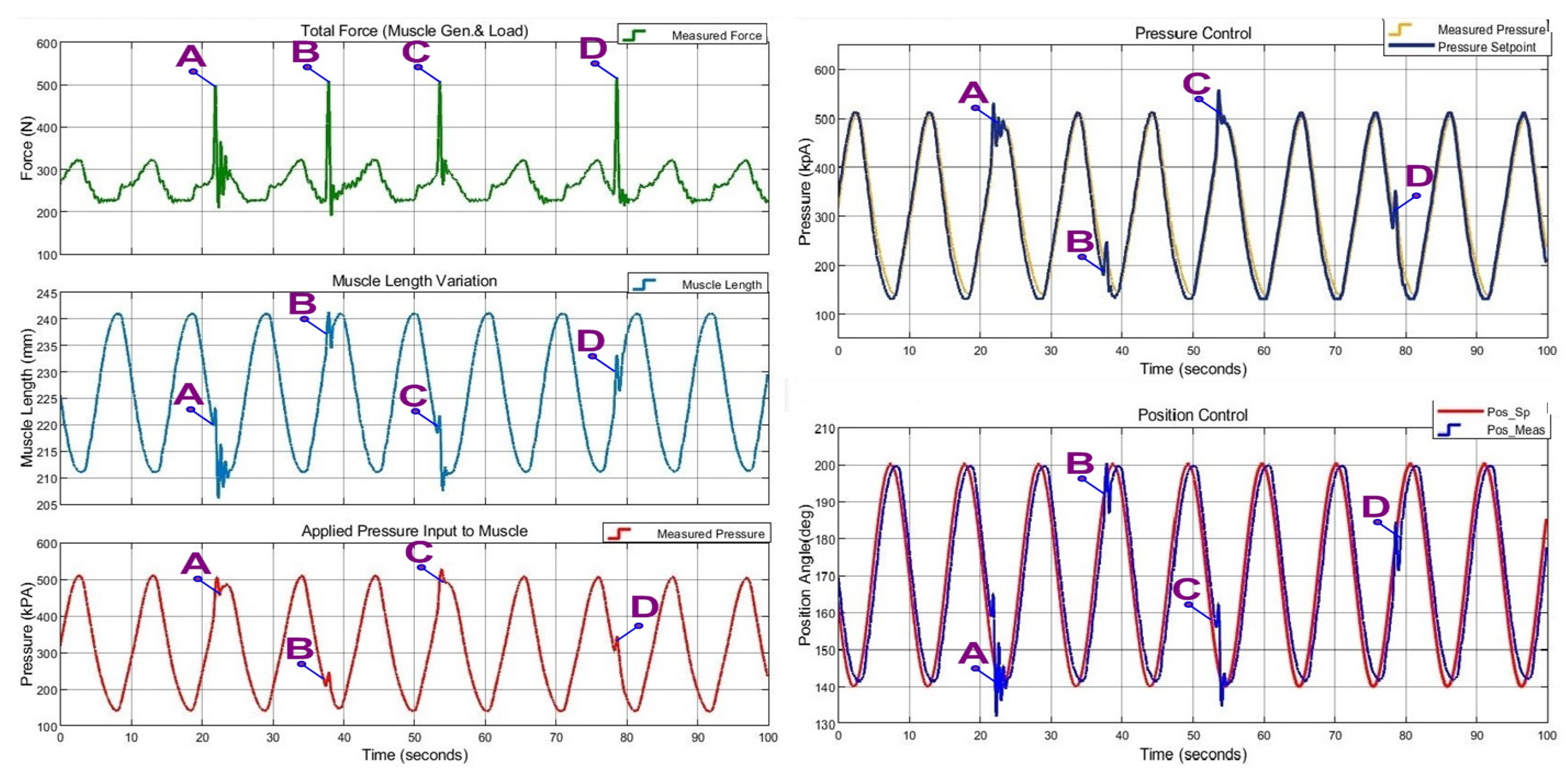
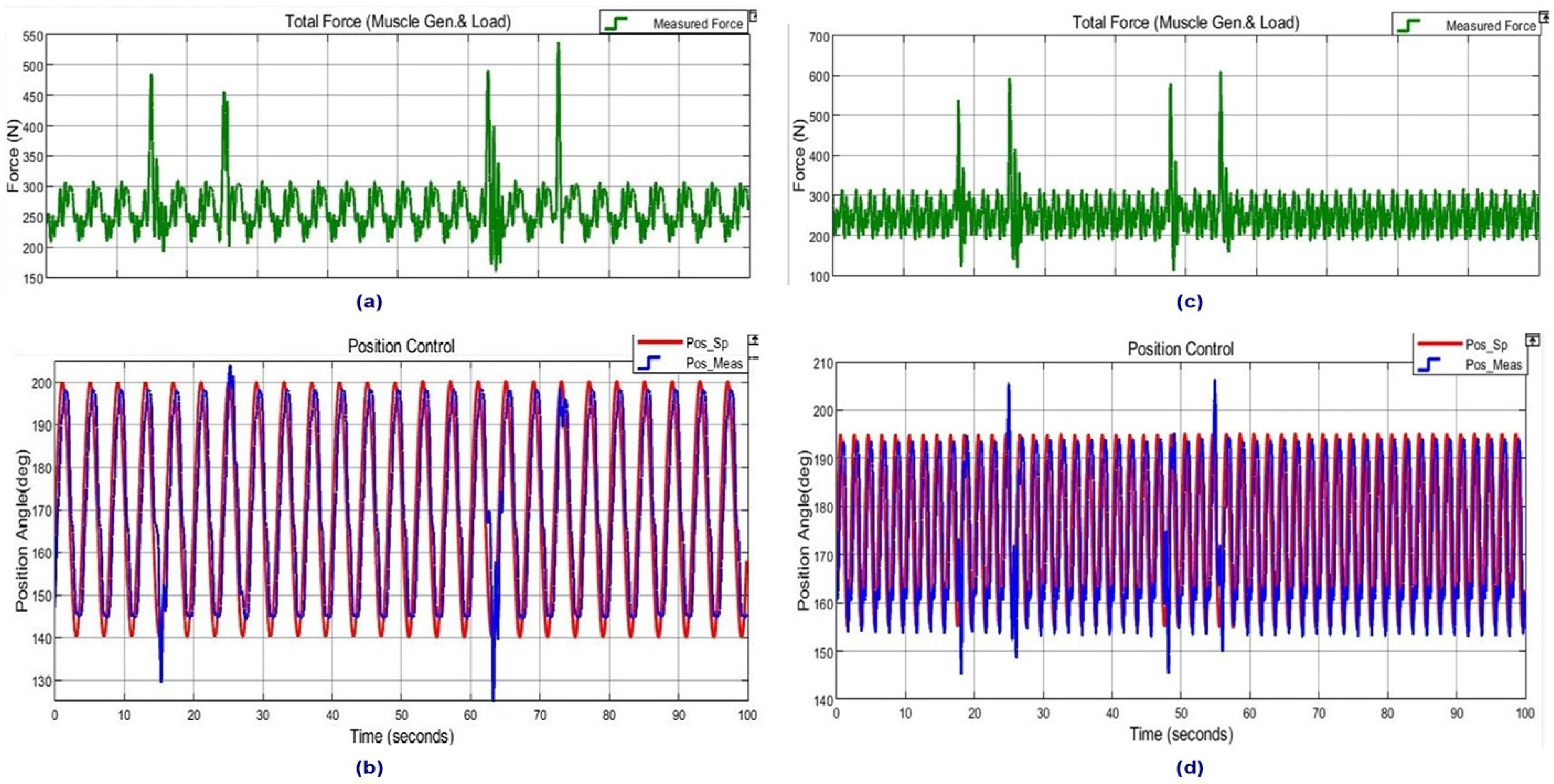
39], NARX-based inverse modeling uses joint angles and end effector contact force as the inputs, valve voltages as outputs, in order to model the complete robotic mechanism. However, this work models the inverse dynamics of PAM itself by taking muscle dynamic length and muscle force as the inputs and muscle pressure as the output, which is independent of the application mechanism. By this means, inverse PAM modeling could be transported to the control applications of different mechanisms. The ROM performance of previous works was limited to approximately 20°.Conversely, this work reached up to 70° ROM with compliance to external disturbances. In addition, the steady-state position error for step response is in the range of −0.52–+1.62°, which is quite acceptable in 60–70° ROM. On the other hand, for sinusoidal trajectories, a higher values of position errors are observed for 0.1 Hz, 0.25 Hz and 0.5 Hz, in the range of−5.5–+3.5°, which is also quite acceptable in 60–70° ROM.
Implementation results demonstrated the efficacy of the novel control system in terms of compliant operation for dynamic external load variations as well as stable operation in case of impulsive disturbances. BIBO-type stable performances of the designed system are also observed. The aims for better compliance to external forces’ variations and estimation of PAM dynamic behavior being independent of application mechanism have been reached. The controller performance videos for compliant operation are presented in supplementary materials.
On the other hand, it could not reach larger ROM higher than 70° due to limitations from the testbed hardware structure. This issue could be resolved in the actual rehabilitation device mechanism design stage.
To conclude, a simple but efficient control method is illustrated to facilitate the common use of PAM in low-cost rehabilitation devices.

Supplementary Materials

The following supporting information can be downloaded at: https://www.mdpi.com/article/10.3390/act11040111/s1; Video S1: CVB1_010Hz_Load_Addition_Subtitled.mp4. Video S2: CVB1_025Hz_Hand_Blockage_Subtitled.mp4. Video S3: CVB1_025Hz_Load_Addition_Subtitled.mp4.

Funding

This research received no external funding.

Institutional Review Board Statement

Not Applicable.

Informed Consent Statement

Not Applicable.

Data Availability Statement

Not Applicable.

Conflicts of Interest

The author declare no conflict of interest.

References

  1. Bogue, R. Rehabilitation robots. Ind. Robot Int. J. 2018, 45, 301–306. [Google Scholar] [CrossRef]
  2. Qian, Z.; Bi, Z. Recent Development of Rehabilitation Robots. Adv. Mech. Eng. 2015, 7, 563062. [Google Scholar] [CrossRef]
  3. Gassert, R.; Dietz, V. Rehabilitation robots for the treatment of sensorimotor deficits: A neurophysiological perspective. J. Neuro Eng. Rehabil. 2018, 15, 46. [Google Scholar] [CrossRef] [PubMed] [Green Version]
  4. Radman, A.; Ismail, W.; Bahari, M. Robotic devices for upper limb stroke rehabilitation: Potential research trends. In Proceedings of the 2017 IEEE International Symposium on Robotics and Intelligent Sensors (IRIS), Ottawa, ON, Canada, 5–7 October 2017; pp. 383–388. [Google Scholar] [CrossRef]
  5. Rehmat, N.; Zuo, J.; Meng, W.; Liu, Q.; Xie, S.Q.; Liang, H. Upper limb rehabilitation using robotic exoskeleton systems: A systematic review. Int. J. Intell. Robot. Appl. 2018, 2, 283–295. [Google Scholar] [CrossRef]
  6. Hobbs, B.; Artemiadis, P. A Review of Robot-Assisted Lower-Limb Stroke Therapy: Unexplored Paths and Future Directions in Gait Rehabilitation. Front. Neurorobotics 2020, 14, 19. Available online: https://www.frontiersin.org/article/10.3389/fnbot.2020.00019 (accessed on 1 March 2022). [CrossRef] [PubMed] [Green Version]
  7. Xie, S.; Zhang, M.; Meng, W. Soft Robots for Healthcare Applications: Design, Modelling, and Control; IET Digital Library: London, UK, 2017. [Google Scholar] [CrossRef]
  8. Belforte, G.; Eula, G.; Ivanov, A.; Sirolli, S. Soft Pneumatic Actuators for Rehabilitation. Actuators 2014, 3, 84–106. [Google Scholar] [CrossRef] [Green Version]
  9. Festo. Fluidic Muscle DMSP/MAS Info 501. 2018. Available online: https://www.festo.com/rep/en_corp/assets/pdf/info_501_en.pdf (accessed on 1 March 2022).
  10. Daerden, F.; Lefeber, D. Pneumatic artificial muscles: Actuators for robotics and automation. Eur. J. Mech. Environ. Eng. 2000, 47, 10–21. [Google Scholar]
  11. Morales, R.; Badesa, F.J.; García-Aracil, N.; Sabater, J.M.; Pérez-Vidal, C. Pneumatic robotic systems for upper limb rehabilitation. Med. Biol. Eng. Comput. 2011, 49, 1145. [Google Scholar] [CrossRef]
  12. Liu, Q.; Zuo, J.; Zhu, C.; Xie, S.Q. Design and control of soft rehabilitation robots actuated by pneumatic muscles: State of the art. Future Gener. Comput. Syst. 2020, 113, 620–634. [Google Scholar] [CrossRef]
  13. Chen, C.-T.; Lien, W.-Y.; Chen, C.-T.; Wu, Y.-C. Implementation of an Upper-Limb Exoskeleton Robot Driven by Pneumatic Muscle Actuators for Rehabilitation. Actuators 2020, 9, 106. [Google Scholar] [CrossRef]
  14. Zhong, J.; He, D.; Zhao, C.; Zhu, Y.; Zhang, Q. A Rehabilitation Robot Driven by Pneumatic Artificial Muscles. J. Mech. Med. Biol. 2020, 20, 2040008. [Google Scholar] [CrossRef]
  15. Deaconescu, A.; Deaconescu, T. Pneumatic Equipment for Ankle Rehabilitation by Continuous Passive Motion. In Advances in Service and Industrial Robotics; Zeghloul, S., Laribi, M.A., Arevalo, J.S.S., Eds.; Springer International Publishing: Berlin/Heidelberg, Germany, 2020; pp. 13–21. [Google Scholar] [CrossRef]
  16. Tsai, T.-C.; Chiang, M.-H. Design and Control of a 1-DOF Robotic Lower-Limb System Driven by Novel Single Pneumatic Artificial Muscle. Appl. Sci. 2020, 10, 43. [Google Scholar] [CrossRef] [Green Version]
  17. Petre, I.; Deaconescu, A.; Rogozea, L.; Deaconescu, T.I. Orthopaedic Rehabilitation Device Actuated with Pneumatic Muscles. Int. J. Adv. Robot. Syst. 2014, 11, 105. [Google Scholar] [CrossRef] [Green Version]
  18. Nguyen, H.T.; Trinh, V.C.; Le, T.D. An Adaptive Fast Terminal Sliding Mode Controller of Exercise-Assisted Robotic Arm for Elbow Joint Rehabilitation Featuring Pneumatic Artificial Muscle Actuator. Actuators 2020, 9, 118. [Google Scholar] [CrossRef]
  19. Zhao, Z.; Xiao, J.; Jia, H.; Zhang, H.; Hao, L. Prescribed Performance Control for the Upper-Limb Exoskeleton System in Passive Rehabilitation Training Tasks. Appl. Sci. 2021, 11, 10174. [Google Scholar] [CrossRef]
  20. Ganguly, S.; Garg, A.; Pasricha, A.; Dwivedy, S.K. Control of pneumatic artificial muscle system through experimental modelling. Mechatronics 2012, 22, 1135–1147. [Google Scholar] [CrossRef]
  21. Tagami, T.; Miyazaki, T.; Kawase, T.; Kanno, T.; Kawashima, K. Pressure Control of a Pneumatic Artificial Muscle Including Pneumatic Circuit Model. IEEE Access 2020, 8, 60526–60538. [Google Scholar] [CrossRef]
  22. Merola, A.; Colacino, D.; Cosentino, C.; Amato, F. Model-based tracking control design, implementation of embedded digital controller and testing of a biomechatronic device for robotic rehabilitation. Mechatronics 2018, 52, 70–77. [Google Scholar] [CrossRef]
  23. Zhang, D.; Zhao, X.; Han, J. Active Model-Based Control for Pneumatic Artificial Muscle. IEEE Trans. Ind. Electron. 2017, 64, 1686–1695. [Google Scholar] [CrossRef]
  24. Xing, K.; Huang, J.; Wang, Y.; Wu, J.; Xu, Q.; He, J. Tracking control of pneumatic artificial muscle actuators based on sliding mode and non-linear disturbance observer. IET Control. Theory Amp Appl. 2010, 4, 2058–2070. [Google Scholar] [CrossRef] [Green Version]
  25. Sun, N.; Liang, D.; Wu, Y.; Chen, Y.; Qin, Y.; Fang, Y. Adaptive Control for Pneumatic Artificial Muscle Systems With Parametric Uncertainties and Unidirectional Input Constraints. IEEE Trans. Ind. Inform. 2020, 16, 969–979. [Google Scholar] [CrossRef]
  26. Hošovský, A.; Novák-Marcinčin, J.; Pitel’, J.; Boržíková, J.; Židek, K. Model-Based Evolution of a Fast Hybrid Fuzzy Adaptive Controller for a Pneumatic Muscle Actuator. Int. J. Adv. Robot. Syst. 2012, 9, 40. [Google Scholar] [CrossRef]
  27. Anh, H.P.H.; Kien, C.V.; Son, N.N.; Nam, N.T. New approach of sliding mode control for nonlinear uncertain pneumatic artificial muscle manipulator enhanced with adaptive fuzzy estimator. Int. J. Adv. Robot. Syst. 2018, 15, 1729881418773204. [Google Scholar] [CrossRef]
  28. Chiang, C.-J.; Chen, Y.-C. Neural network fuzzy sliding mode control of pneumatic muscle actuators. Eng. Appl. Artif. Intell. 2017, 65, 68–86. [Google Scholar] [CrossRef]
  29. Chavoshian, M.; Taghizadeh, M.; Mazare, M. Hybrid Dynamic Neural Network and PID Control of Pneumatic Artificial Muscle Using the PSO Algorithm. Int. J. Autom. Comput. 2020, 17, 428–438. [Google Scholar] [CrossRef]
  30. Baysal, C.V. Neural Network Based Inverse Modelling for Pneumatic Artificial Muscles. Eur. J. Sci. Technol. 2020, 142–149. [Google Scholar] [CrossRef]
  31. Anh, H.P.H. Inverse Dynamic model identification of 2-axes PAM robot arm using neural MIMO NARX model. In Proceedings of the 2009 IEEE/ASME International Conference on Advanced Intelligent Mechatronics, Singapore, 14–17 July 2009; pp. 1282–1287. [Google Scholar] [CrossRef]
  32. Gomi, H.; Kawato, M. Neural network control for a closed-loop System using Feedback-error-learning. Neural Netw. 1993, 6, 933–946. [Google Scholar] [CrossRef]
  33. Nakanishi, J.; Schaal, S. Feedback error learning and nonlinear adaptive control. Neural Netw. 2004, 17, 1453–1465. [Google Scholar] [CrossRef] [Green Version]
  34. Tiumentsev, Y.V.; Egorchev, M.V. Neural Network Black Box Approach to the Modeling and Control of Dynamical Systems. In Neural Network Modeling and Identification of Dynamical Systems; Tiumentsev, Y.V., Egorchev, M.V., Eds.; Academic Press: Cambridge, MA, USA, 2019; pp. 93–129. [Google Scholar] [CrossRef]
  35. Marcello, F.B.; Scattolini, F.R. Stability of discrete-time feed-forward neural networks in NARX configuration. IFAC PapersOnLine. 2021, 54, 547–552. [Google Scholar] [CrossRef]
  36. El Hamidi, K.; Mjahed, M.; El Kari, A.; Ayad, H. Adaptive Control Using Neural Networks and Approximate Models for Nonlinear Dynamic Systems. Modeling Simul. Eng. 2020, 2020, 8642915. [Google Scholar] [CrossRef]
  37. Anh, H.P.H.; Ahn, K.K. Hybrid control of a pneumatic artificial muscle (PAM) robot arm using an inverse NARX fuzzy model. Eng. Appl. Artif. Intell. 2011, 24, 697–716. [Google Scholar] [CrossRef]
  38. Yu, H.; Wilamowski, B. LevenbergMarquardt Training. In Industrial Electronics Handbook, 2nd ed.; Intelligent Systems; CRC Press: Boca Raton, FL, USA, 2011; Volume 5, Chapter 12; pp. 12-1–12-15. [Google Scholar]
  39. Anh, H.P.H.; Van Kien, C.; Nam, N.T. Advanced force control of the 2-axes PAM-based manipulator using adaptive neural networks. Robotica 2018, 36, 1333–1362. [Google Scholar] [CrossRef]
Figure 1. Diagrams for the single PAM-actuated elbow orthosis (a) and CPM device (b).
Actuators 11 00111 g001
Figure 2. Rotating arm PAM testbed representing rehabilitation devices.
Actuators 11 00111 g002
Figure 3. Festo pneumatic artificial muscle and dynamic characteristics [9].
Actuators 11 00111 g003
Figure 4. Block diagram of data acquisition setup.
Actuators 11 00111 g004
Figure 5. Hardware implementation and structure of 1DoF rotating arm PAM testbed.
Actuators 11 00111 g005
Figure 6. Block diagram of proposed adaptive nonlinear control system.
Actuators 11 00111 g006
Figure 7. NARX Structures: (a) series-paralleland (b) parallel.
Actuators 11 00111 g007
Figure 8. Implemented MISO NARX block diagram (series-parallel).
Actuators 11 00111 g008
Figure 9. MATLAB implementation of MISO NARX.
Actuators 11 00111 g009
Figure 10. Training performance of NARX.
Actuators 11 00111 g010
Figure 11. Regression results for NARX.
Actuators 11 00111 g011
Figure 12. Overall Control System Simulink Block Diagram.
Actuators 11 00111 g012
Figure 13. Pressure loop PID responses after tuning: (a) step response and (b) 0.25 Hz sinusoidal reference.
Actuators 11 00111 g013
Figure 14. Overview of NARX estimation-based control response at 0.1 Hz sinusoidal trajectory tracking operation. I: isotonic extension, II: isotonic flexion, and III: quasi-isometric contraction. For I F = 229.5 N, II F = 263.1 N, and III F = 315.7 N.
Actuators 11 00111 g014
Figure 15. Overview of NARX estimation-based control response at step reference trajectory tracking operation.
Actuators 11 00111 g015
Figure 16. Position trajectory responses when NARX estimation-based control is active: (a) step reference, (b) 0.1 Hz sinusoidal reference, (c) 0.25 Hz sinusoidal reference, and (d) 0.50 Hz sinusoidal reference.
Actuators 11 00111 g016
Figure 17. Position error for step response when NARX estimation-based control is active.
Actuators 11 00111 g017
Figure 18. Position errors for sinusoidal trajectories when NARX estimation-based control is active.
Actuators 11 00111 g018
Figure 19. Performance comparison results for 0.25 Hz sinusoidal reference position tracking: (a) PID-only operation and (b) NARX active operation.
Actuators 11 00111 g019
Figure 20. Performance comparison results for step reference position tracking: (a) PID-only operation and (b) NARX active operation.
Actuators 11 00111 g020
Figure 21. Control system response during NARX activation–deactivation transitions at 0.25 Hz sinusoidal position trajectory.
Actuators 11 00111 g021
Figure 22. Dynamic external load addition and removal responses at 0.10 Hz sinusoidal position trajectory.
Actuators 11 00111 g022
Figure 23. Dynamic external load addition and removal performance comparison results for 0.25 Hz sinusoidal reference position tracking: (a,b) PID-only operation and (c,d) NARX active operation responses.
Actuators 11 00111 g023
Figure 24. External load addition and removal performance comparison results: (a,b) for 0.50 Hz sinusoidal reference position tracking and (c,d) for step reference position tracking.
Actuators 11 00111 g024
Figure 25. Impulsive force load application and overall system response at 0.1 Hz sinusoidal trajectory tracking operation.
Actuators 11 00111 g025
Figure 26. Impulsive force load application and system responses at 0.25 Hz (a,b)and 0.50 Hz sinusoidal trajectory tracking (c,d).
Actuators 11 00111 g026
Table 1. Hardware specifications of 1 DoF rotating arm PAM testbed.
ItemSpecifications
Control Unit and I/O Interface Circuits Atmel, Arm Cortex-M3 CPU, Signal Amplifier, and Valve Drive Circuits
Encoder for Arm Position Angle (Enc)Bourne, AMS22S5A1, 0.1 deg resolution
Pneumatic Artificial Muscle (PAM)Festo, DMSP 20–250, 0–6 bar, L: 250 mm
Pressure Sensor (PS)Honeywell, 24PCFF, 0–100 psi
Proportional Directional Control ValveFesto, MPYE-5-M5
Force Sensor (LD)Zemic, H3-P3 load cell, 0–100 kg
Table 2. 1 DoF PAM testbed physical quantities andoperation range.
ItemDescriptionRange/Value
θmPAM testbed load arm position angle120–230 deg
θminTestbed load arm minimum angle 120 deg
LmPAM dynamic length 200–257 mm
LminPAM minimum operation length 200 mm
LmcontrPAM contraction length: (LmLmin)0–57 mm
ΩRadial coefficient for testbed load arm29.5
PmPAM-applied pressure 0–690 kPA
FmPAM testbed measured total force0–1000 N
FwTotal weight (applied load + arm)2.83–137.5 N
FLEffective load force applied to PAM20.6–1000 N
KgTestbed load arm lever gain: l2/l17.28
γLoad vertical inclination angle0–50 deg
Table 3. Symbols used in proposed control system block diagram.
SymbolMeaning
r(k) Position control loop reference value
θm(k) PAM testbed arm position angle
e1(k) Position control loop error
pr(k) Pressure loop reference value from position controller
pest(k) Pressure feedback value from inverse dynamics estimator
e2(k)Pressure control loop error
u(k) Pressure controller output
y(k) PAM testbed output
pm(k) PAM-applied pressure
fm(k) PAM testbed total force (PAM generated + load)
Table 4. Symbols used in MISO NARX.
SymbolMeaning
u1(k) First exogenous input from system via measurement (muscle dynamic length)
u2(k) Second exogenous input from system via measurement (muscle total force)
y1(k) Output feedback from system via measurement (pressure)
y2(k) NN-NARX estimated output to be used for control system feedback (pressure)
q−1Time delay operator
xiith element of input vector
b1Bias vector for hidden layer nodes
ΣNode summation function
ψActivation function for hidden layer
w1j,iWeight between input nodei and hidden layer node j
λjOutput of hidden layer node j
w2o,jWeight between hidden node j and output layer node o
b2Bias vector for output layer node
ΦActivation function for output layer
Table 5. Numerical values for critical points marked in Figure 21.
ItemPoint XPoint Y
Time (sec)13.8345.88
Force (N)290.3270.9
Muscle Length (mm)238.9216.2
Applied Pressure (kPa)241.2559.4
Pressure Control Setpoint (kPa)241.3558.0
Position Angle (deg)195.6158.3
Position Control Setpoint (deg)180.5157.1
Table 6. Numerical values for critical points marked in Figure 22.
ItemPoint XPoint Y
Time (sec)20.5949.24
Force (N)269.9303.5
Muscle Length (mm)227.7242.1
Applied Pressure (kPa)299.2154.7
Pressure Control Setpoint (kPa)317.2147.9
Position Angle (deg)173.8201.5
Position Control Setpoint (deg)169.6205
Table 7. Numerical values for critical points in Figure 25.
ItemPoint APoint BPoint CPoint D
Time (sec)21.8537.8553.5178.56
Force (N)497.5507.9504.7515.8
Muscle Length (mm)223.2241.3221.7233.1
Applied Pressure (kPa)482.7245.7493.5343.4
Pressure Control Setpoint (kPA)530.9248.2551.6351.6
Position Angle (deg)161.5197.5156.4183.5
Position Control Setpoint (deg)147.5195.6156.1184.1
Publisher’s Note: MDPI stays neutral with regard to jurisdictional claims in published maps and institutional affiliations.

