Article

Study on Buckling Characteristics of a Convex Tape-Shaped Ti-Ni Shape Memory Alloy Element for Application to Passive Vibration Isolator Devices and Force Limit Devices

Department of Mechanical Systems Engineering, The University of Kitakyushu, Kitakyushu 8080135, Japan
*
Author to whom correspondence should be addressed.
Actuators 2022, 11(3), 88; https://doi.org/10.3390/act11030088
Submission received: 17 February 2022 / Revised: 8 March 2022 / Accepted: 12 March 2022 / Published: 14 March 2022
(This article belongs to the Special Issue Smart Materials for Smart Actuators and Semi-active Components)

Abstract

:
The tape-shaped Ti-Ni shape memory alloy (SMA) shows negative or quasi-zero stiffness during post-buckling deformation, and this characteristic can be applied to passive vibration isolator devices and force limit devices. Design calculation of the buckling load and the negative stiffness gradient after buckling of tape-shaped SMA element are required to apply the SMA element to these devices. When the cross-section of the SMA element is convex tape shaped, an improvement in buckling properties is expected. In this study, the effects of the curvature of the cross-section on the buckling characteristics of convex tape-shaped SMA elements were investigated by the 3D finite element method (3D-FEM) and material testing. The results of the study indicate that the buckling load and negative stiffness gradient of convex tape-shaped SMA elements tend to increase with increasing curvature of the cross-section. Furthermore, when the convex tape-shaped SMA elements buckled in the convex direction of the cross-section, the loading stress was approximately equivalent to that of buckling a flat tape-shaped SMA elements. Therefore, the convex tape-shaped SMA element is considered to be more suitable for device application compared to the flat tape-shaped SMA element, because the buckling characteristics of convex tape-shaped SMA elements can be controlled by adjusting the curvature of the cross-section without changing the dimensions.

1. Introduction

Shape memory alloy (SMA) is a metallic material that has the ability to recover its shape after deformation due to phase transformation [1,2]. Since the phase transformation is due to chemical changes, the shape recovery is caused by temperature variation or stress (pressure) variation. Therefore, shape memory alloys may recover their shape autonomously or by heating, depending on the temperature and stress environment. This autonomous shape recovery is called superelasticity, while shape recovery by heating is referred to as the material’s shape memory properties. Since Ti-Ni SMA shows superior properties in terms of shape memory effects, ductility, toughness, fatigue resistance, corrosion resistance and abrasion resistance [3,4,5], the Ti-Ni SMA has applications in various fields. Applications of the superelasticity of Ti-Ni SMA include medical products such as orthodontic wires and self-expanding stents [6,7], as well as consumer products such as eyeglass frames. Furthermore, applications of the shape memory properties of Ti-Ni SMA include in medical devices such as the brain spatula (retractor) [8], and consumer devices such as temperature sensors [9] and haptic devices [10].
Examples of research on the possible application of shape memory properties include heat engines for energy recovery from waste-heat such as hot water [11,12,13], and actuators with electrical heating [14,15,16]. On the other hand, application research examples of superelastic properties include space equipment such as tires for planetary probes [17], deployable rocket nozzles [18], and damping devices [19]. Damping devices using SMA are designed to damp vibration energy by using the stress hysteresis of the superelastic properties of shape memory alloys. This mechanism is effective in damping large vibrations such as earthquakes, but has difficulty absorbing smaller vibrations such as the vibration of a machining tool.
We focused our research on the mechanical properties of tape-shaped SMA during buckling deformation, especially the negative or quasi-zero stiffness during post-buckling deformation. It has already been reported by research in the architectural and automotive fields that long columnar or linear Ti-Ni SMA shows negative stiffness during the post-buckling process [20,21,22,23], as shown in Figure 1.
However, these studies were mainly interested in the recovery of deformation after buckling or the suppression of buckling. We developed a quasi-zero stiffness structure by combining tape-shaped SMA elements and normal springs in parallel, as shown in Figure 2. The spring modulus of this structure is the sum of the spring modulus of each element. Therefore, when combined with a spring that offsets the negative stiffness of the SMA element, this structure can be made into a quasi-zero structure, which can be used as a vibration isolator. In addition, this mechanism can support weight up to the buckling load (Pcr) of the SMA element. Therefore, this mechanism is simpler and lighter than conventional vibration isolators that use a zero stiffness structure with nonlinear springs [24,25]. We fabricated a prototype of the proposed vibration isolator device using a tape-shaped SMA element and reported that it showed superior vibration-isolation characteristics [26]. Furthermore, tape-shaped SMA elements can be used as force limit devices that do not transmit a force above the Pcr of the SMA element, for example as a force limit device for forceps for medical use [27].
As mentioned previously, the buckling property of tape-shaped SMA elements has various applications. However, design calculation of the Pcr and the negative stiffness gradient after buckling of tape-shaped SMA element are required when applying the SMA element to devices. Hence, we investigated the effect of the slenderness ratio of the SMA elements on the post-buckling properties, and the design calculations for application in devices using the tape shape SMA element [28,29]. However, in addition to the slenderness ratio, the cross-sectional shape also influences the buckling characteristics of the element, and when the cross-section of the SMA element is convex tape shaped, a significant change in the buckling characteristics is expected. In this study, the effects of the curvature of the cross-section on the buckling characteristics of convex tape-shaped SMA elements were investigated by the 3D finite element method (3D-FEM) and material testing, and the application of the convex tape-shaped SMA elements to passive vibration isolator devices and force limit devices was investigated.

2. Materials and Methods

2.1. Convex Tape Shaped Ti-Ni Element

The convex tape is a tape-like material with a curved cross-section. The curvature of the cross-section (κ) is obtained as the inverse of the radius of curvature (ρ). The increase of cross-sectional curvature (κ) leads to an increase in the second moment of area (Iz) compared to a flat tape shape, and this leads to an increase in elastic force. This characteristic is used in tape measures, as a familiar example, and its application to space equipment is also being researched [30]. The Pcr of a columnar material with uniform cross-section is determined by the Euler’s Column Formula, as follows:
P cr = C π 2 E I z l 2
where C is the factor accounting for the end conditions, E is Young’s modulus, and l is the length of the column. Since the specimen mounting conditions for the buckling test in this study are “both ends built in” (fixed), the C is 4. The Pcr is inversely proportional to the square of l and proportional to the Iz. Hence, the buckling characteristics of columnar material with uniform cross-section depend on the slenderness ratio and the cross-sectional shape. In this study, we focused on the cross-sectional shape of tape-shaped Ti-Ni SMA element and investigated the buckling characteristics of a convex tape-shaped Ti-Ni SMA element.
Figure 3 shows (a) the flat tape-shaped and (b) convex tape-shaped Ti-Ni SMA element fabricated in this study and (c) the schematic drawing of the heat-treatment method for tape-shaped Ti-Ni SMA elements. Specimens were made of the same tape-shaped Ti-Ni SMA, provided by Yoshimi, Inc., and the dimensions were 5.35 mm in width and 0.2 mm in thickness. This tape-shaped SMA was cut to 50 mm and memorized into flat and convex shapes by heat treatment at 673 K for 3.6 ks under constraint to the shape, as can be seen in Figure 3c. The κ values of convex specimens are 0.05, 0.067, and 0.08 mm−1 for curvature radii (r) of 20.0, 15.0, and 12.5 mm, respectively. The κ in this study was set so that the specimens could be fabricated under identical heat treatment conditions. The reverse transformation finish temperature of the heat-treated SMA specimen was 302.9 K, measured by differential scanning calorimetry (DSC).
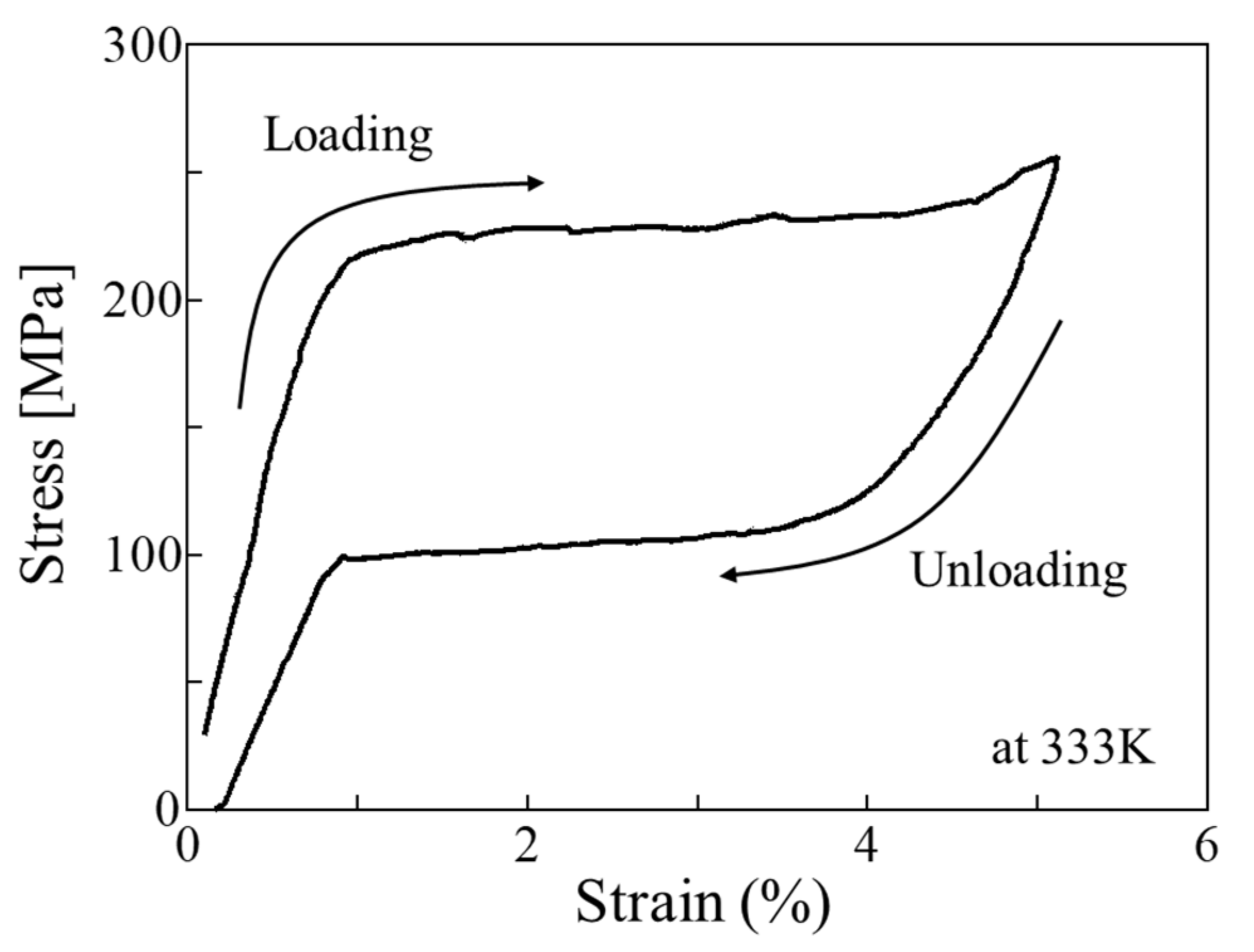
Figure 4 shows the stress–strain curve of the heat-treated Ti-Ni SMA element with a flat tape shape obtained by tensile testing at 333 K. Since 333 K is above the reverse transformation finish temperature of the heat-treated SMA specimen, the heat-treated SMA specimen exhibits excellent superelastic properties. Therefore, the environmental temperature for the experiments in this study was set at 333 K.

2.2. Material Testing

Figure 5 shows the schematic drawing of the buckling testing machine used in this study. In the buckling test, 10 mm at both ends of the specimen were used as the gripping area, so the gauge length of the SMA specimen was 30 mm. As shown in Figure 6, the test specimen was placed in an oil bath in the testing machine. Therefore, a constant test temperature was maintained during buckling tests. The relationships between the reaction force and the buckling displacement of the SMA specimens were analyzed and compared to the data acquired by the load cell and laser displacement meter. The applied buckling displacement was 3 mm, which corresponds to 10% of the length of the specimen.
Incidentally, it is impossible to fabricate a perfectly vertical tape-shaped SMA specimen and to apply a perfectly vertical force to the SMA specimen. Therefore, the SMA specimen always buckles when a compressive force is applied by this machine. Moreover, when a convex tape-shaped elements buckles, there are two different directions of buckling; in the direction of convex cross-section (forward direction) and vice versa (reverse direction) as shown in Figure 6. In this study, a comparative study of the characteristics of these two types of buckling directions was also conducted.

2.3. 3D-FEM Analyses

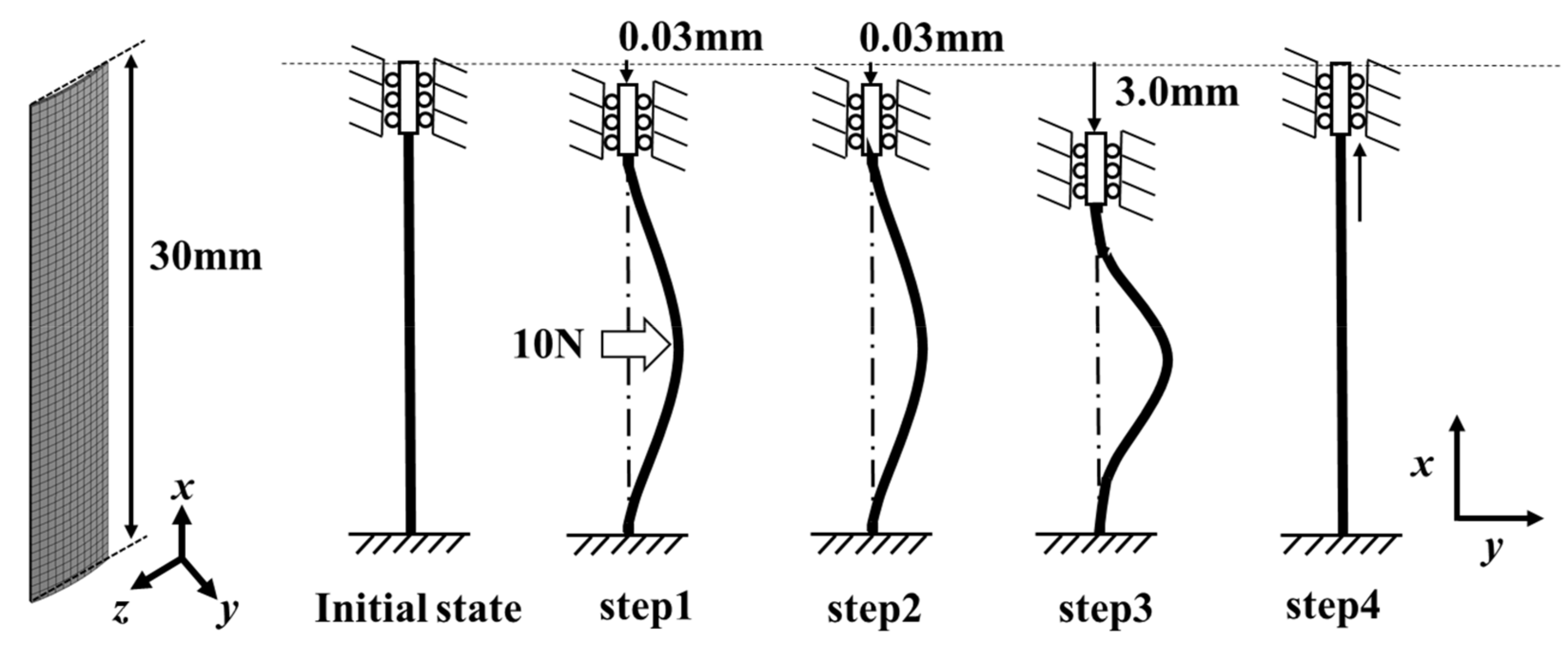
The 3D-FEM analyses were conducted using the ANSYS Workbench software to analyze the buckling behavior of the tape-shaped SMA element. Figure 7 shows the three-dimensional model (3D model) of convex tape-shaped SMA element used in the software and the process of analysis of the buckling behavior of the tape-shaped SMA element. The dimensions of the 3D model are the same as those of the specimen used in the material experiment. The size of one element in the x and z directions (length and width directions) was 0.5 mm, and a total of 7 elements were arranged in the y direction (thickness direction). The number of node points in the 3D model was set to about 3000. Since 3D models of the SMA specimen are perfectly vertical and the compressive force to be applied is also perfectly vertical in the software, 3D models in the software do not buckle during simulations of compression deformation. Hence, we consider a 4-step sequence during buckling deformation in the software. In step 1, a 10 N horizontal force is applied to the center of the material with a 0.03 mm (0.1% of the length of specimen) buckling displacement of the upper end of material to induce buckling. This horizontal force and buckling displacement cause a buckled shape to be imparted to the material. Incidentally, the applied horizontal force and deformation used in this study were the smallest values available for simulation of buckling deformation. In addition, the buckling direction shown in Figure 6 can be controlled by the direction of the applied horizontal force. In step 2, the horizontal force on the center of the materials is removed. The buckled form is maintained because the 0.03 mm buckling deformation is retained. In step 3, the buckling deformation is increased from 0.03 mm to 10 mm and the 3D model is buckled. Finally, the buckling displacement is removed in step 4.
In this study, the relationship between the buckling deformation and the reaction force of the bottom end during step 3 and step 4, and stress analysis during step 3 and step 4 are investigated. Step 1 and step 2 are excluded from the analysis results because the horizontal force applied to the center of materials is a simulated external force.
Figure 8 shows the stress–strain curve of heat-treated Ti-Ni SMA element with flat tape shape obtained by the tensile test at 333 K and of the material model input into the software. The simulated stress–strain curve was constructed based on this actual stress–strain curve. The martensite-induced stress (σM) is 220 MPa and the simulated stress–strain curve in this study transitions from phase transformation platform stress to elastic deformation when the strain is above 5%. In addition, plastic deformation is not considered in the calculation.

3. Results and Discussions

3.1. Effects of Curvature of the Cross-Section on Buckling Characteristics

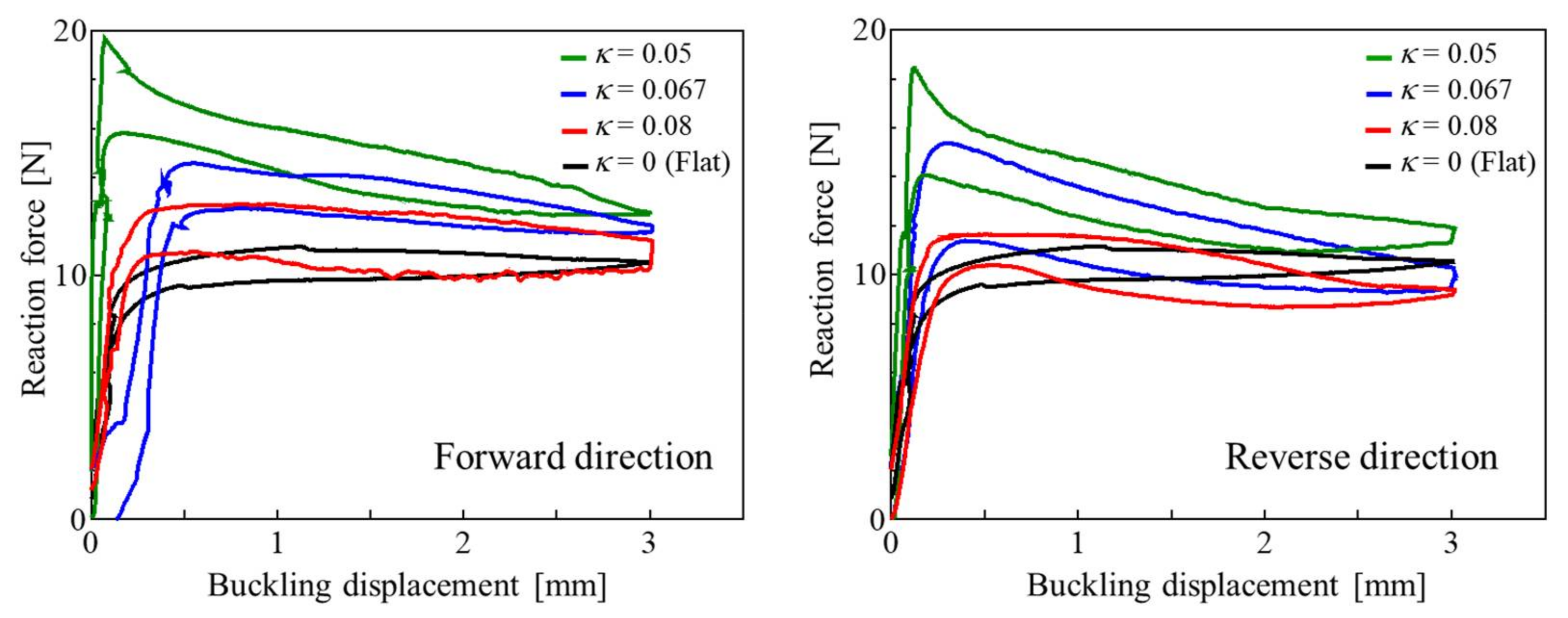
The numerically obtained relationships between the reaction force and buckling displacement of the flat and convex tape-shaped SMA elements in each buckling direction are shown in Figure 9. Each numerical result shows negative stiffness during post-buckling deformation. Pcr and negative stiffness gradient tend to increase with increasing κ. Furthermore, when the buckling deformation is above 1 mm, the negative stiffness gradient tends to become almost constant regardless of the cross-sectional shape and buckling direction.
These tendencies are thought to be caused by the increase in Pcr with increasing κ and the reaction force at 3 mm. The Pcr is proportional to the Iz, and Iz increases with increasing κ. Therefore, it is expected that Pcr tends to increase with increase in κ even in the region where κ is above 0.08. On the other hand, numerical analysis confirmed that the overall buckling shape at 3 mm buckling deformation was almost the same regardless of the κ and buckling direction. Therefore, it is thought that the reaction force at 3 mm buckling deformation becomes almost constant regardless of the curvature of the cross-section or buckling direction. Since the negative stiffness gradient is determined by the difference between the Pcr and reaction force at 3 mm buckling, the negative stiffness gradient increases with increasing κ. The tendency for the overall buckling shape to approach approximately the same shape when the buckling deformation is sufficiently advanced is thought to be due to the large stress platform of SMA. However, further investigation is required and planed for a future study. In addition, when the buckling direction is in the reverse direction, the reaction force tends to increase slightly compared to the forward directional buckling. The details are discussed in Section 3.2, this tendency is attributed to the variation of the cross-sectional shape during buckling deformation due to the difference in the buckling direction.
To verify the results of the numerical analysis, experiments were conducted on actual samples. The experimentally obtained relationships between the reaction force and buckling displacement of the flat and convex tape-shaped SMA elements in each buckling direction are shown in Figure 10. As mentioned earlier, the specimen used in the experiment was not completely uniform in shape, and it is difficult to completely fix the specimen in a perfect vertical position and to apply a load that is purely oriented in the axial direction of the specimen. Therefore, the buckling direction changes in the forward or reverse direction depending on the specimen and experimental conditions. This is because there is no great difference in Pcr between the forward and reverse directions. However, the results obtained from the experiments show a shift in the displacement starting point and the reaction force fluctuations as can be seen Figure 10. On the other hand, the numerical analysis results have certain tendencies in common with the experimental results. The Pcr and negative stiffness gradient increase with increasing κ, and the negative stiffness gradient becomes almost constant, regardless of the cross-sectional shape and buckling direction, when the buckling deformation is above 1 mm. Therefore, the results of the numerical analysis are thought to be consistent.
As mentioned earlier, Pcr and negative stiffness gradient during buckling deformation of a tape-shaped SMA element have to be adjusted for the application of tape-shaped SMA elements in devices. Conventionally, the Pcr and negative stiffness gradient of a tape-shaped SMA element is controlled by modifying the slenderness ratio and the cross-sectional area of the material. However, these results suggest that Pcr and negative stiffness gradient during buckling deformation could be adjusted by adding curvature without changing the dimensions of the material.

3.2. Structure and Stress Analyses

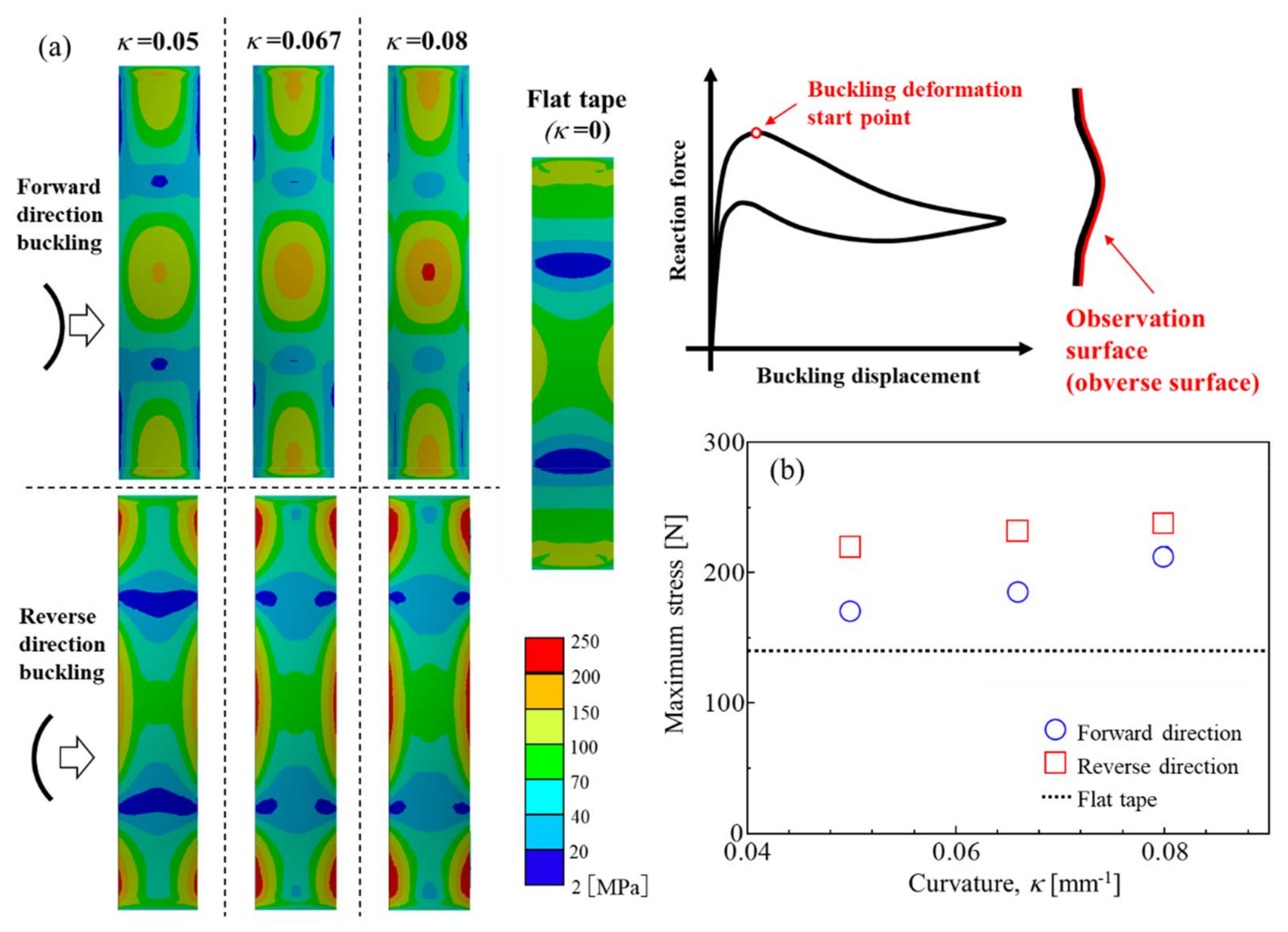
The deformed shape and stress distribution of each specimen were analyzed by 3D-FEM at the buckling deformation start point (when the reaction force is Pcr) and at 3 mm buckling deformation. The main type of deformation in buckling deformation is bending deformation, and the maximum stress for bending deformation is generated at the material surface. Furthermore, there are two types of surface (the obverse and reverse of the specimen) due to buckling, as shown in Figure 11. Therefore, stress analyses were performed on the obverse and reverse surfaces of the specimen in this study.
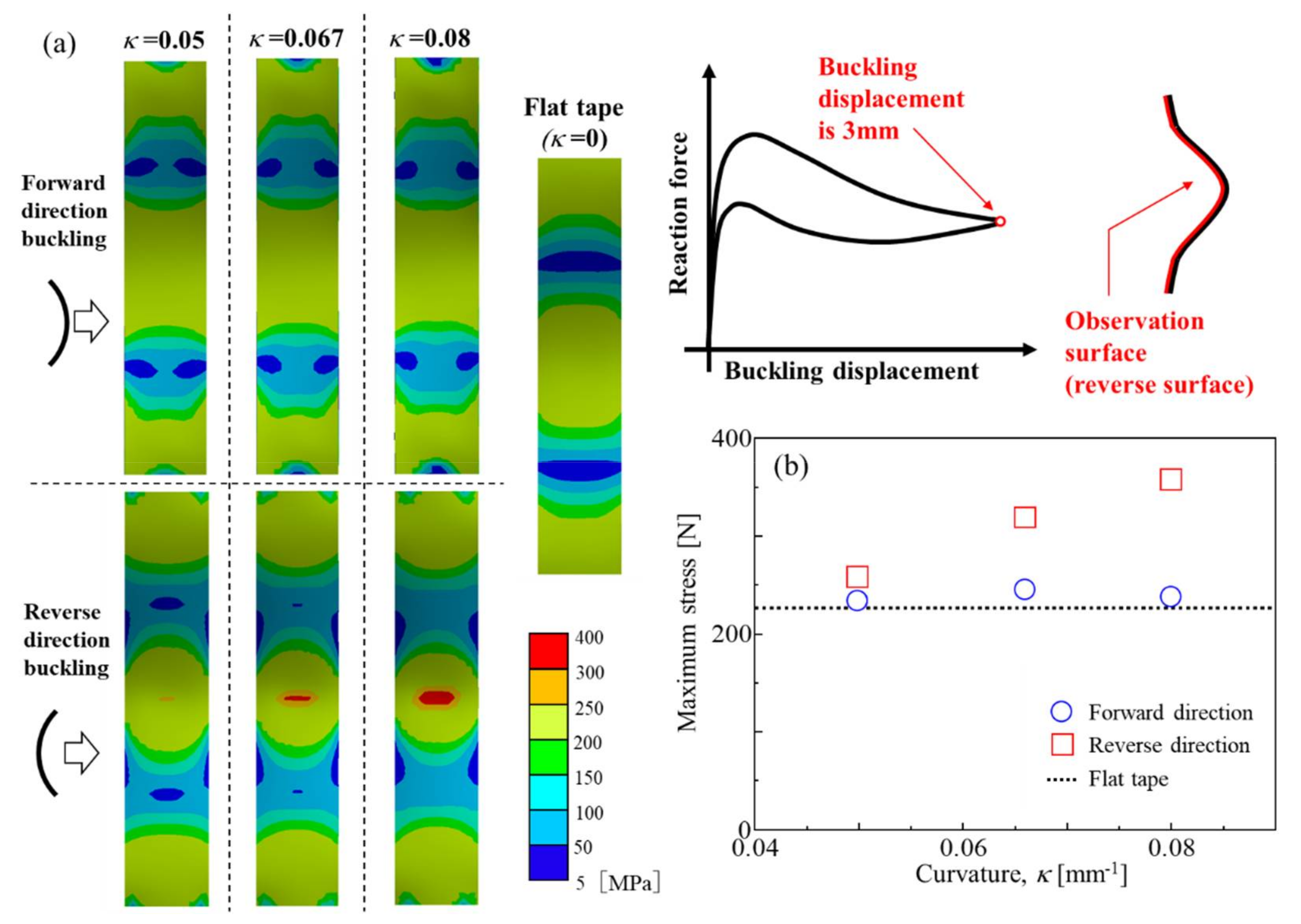
Figure 12 shows the numerically obtained (a) stress distribution and (b) κ dependence of maximum stress on the obverse surface of each specimen for each buckling direction at the buckling deformation start point. According to the stress distribution, the stress is concentrated in three locations (both ends and the center) at which bending deformation is applied during buckling deformation. Moreover, it can be seen that the stress is concentrated in the center of the material for forward buckling, but in the side of the material for reverse buckling. Furthermore, the maximum stress tends to be larger in the reverse direction than in the forward direction, and the maximum stress tends to increase with increasing κ regardless of the buckling direction.
The numerically obtained stress distribution and κ dependence of maximum stress on the reverse surface of each specimen for each buckling direction at the buckling deformation start point are shown in Figure 13. The trend of the maximum stress is similar to that of the obverse surface. However, the stress is concentrated in the side of the material for forward buckling, but in the center of the material for reverse buckling. These tendencies are due to the fact that the cross-section of the deformed area approaches a linear shape, as will be discussed later. Thus, it is thought that a larger stress is applied to the section that needs to be deformed more when the cross-section is deformed into a straight shape.
Figure 14 shows the numerically obtained (a) stress distribution and (b) κ dependence of maximum stress on the obverse surface of each specimen for each buckling direction, when the buckling displacement is 3 mm. It can be seen that the stress is concentrated in three locations. These three locations are the same at the buckling deformation start point, as well as with a buckling displacement of 3 mm, as can be seen when comparing Figure 12, Figure 13 and Figure 14. However, while the stresses are relatively uniform in the case of forward buckling and flat tape-shape, there is a concentration of stress at the center of the material in the case of reverse buckling, as can be seen in Figure 14. Focusing on the maximum stress, in the case of forward buckling, the stress is approximately equal in a flat tape shape, regardless of the κ. On the other hand, the maximum stress tends to increase with increasing κ in the case of reverse buckling.
The numerically obtained stress distribution and κ dependence of maximum stress on the reverse surface of each specimen for each buckling direction when the buckling displacement is 3 mm are shown in Figure 15. It can be seen that the trend of stress distribution and maximum stress on the reverse surface is also approximately similar to the trend of the obverse surface, as can be seen in Figure 14.
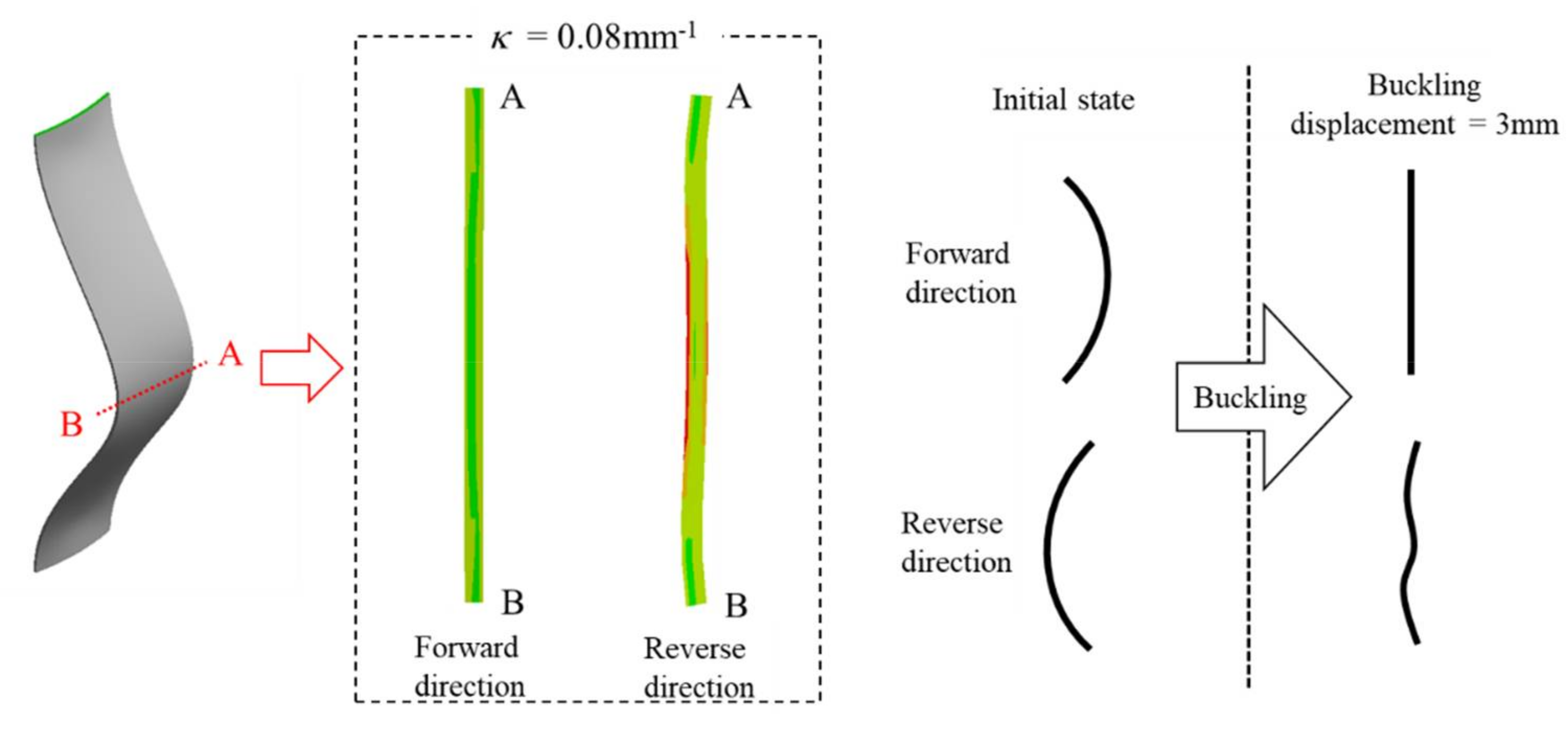
To investigate the cause of the stress concentration in the case of reverse buckling, a comparison of the cross-sectional shape of the center of the specimen was carried out. Figure 16 shows the numerically obtained results and schematic drawings of the cross-sectional shape. It shows the center of the material for forward and reverse buckling with κ = 0.08 mm−1, when the buckling displacement is 3 mm. It can be seen that the cross-sectional shape of the forward buckling specimen is approximately a straight-line, while the cross-sectional shape of the reverse buckling specimen is a cosine-curve shape close to straight line shape. In addition, the center of the cross-section has a curvature in the opposite direction to the convex.
These results suggest that the cross-sectional shape of the center of the material deforms to a near-linear shape as the buckling deformation progresses, regardless of the buckling direction. In the case of forward buckling, the cross-section deforms uniformly to a near-linear shape, and the stress is uniformly distributed. Meanwhile, in the case of reverse buckling, deformation is concentrated in the center of the material and the cross-section deforms to a near-linear shape. Therefore, the cross-section is deformed into a cosine curve due to residual curvature at both ends and in the center of the specimen. In addition, the difference in cross-sectional shape during buckling deformation is thought to be the cause of the slight increase in reaction force in the case of reverse buckling compared to that of forward buckling as can be seen in Figure 9.
The deformation concentration in the center of the cross-section leads to the stress concentration in the center of the specimen, and it can lead to a decrease in the lifetime of the tape-shaped SMA element. Therefore, forward buckling, which does not cause stress concentration, is considered to be more suitable for application with respect to the convex tape-shaped SMA element. In addition, since the loading stress of the forward-buckled convex tape-shaped specimen is approximately equal to that of the flat tape-shaped specimen, the passive vibration isolator devices and force limit devices using the forward-buckled convex tape-shaped SMA element can be expected to have a product lifespan almost equal to that of a flat tape-shaped SMA element.

4. Conclusions

The effects of the curvature of the cross-section (κ) on the buckling characteristics of convex tape-shaped SMA elements were investigated by means of the 3D finite element method (3D-FEM) and material testing, and the application of the convex tape-shaped SMA elements to passive vibration isolator devices and force limit devices was also investigated. The obtained results can be summarized as follows:
(1)
The buckling load (Pcr) and the negative stiffness gradient of the convex tape-shaped SMA element increased with increasing κ. The increase of Pcr was mainly due to the increase of the second moment of area with increasing κ. On the other hand, regardless of the κ or the buckling direction, the overall buckling shape will approach approximately the same shape when the buckling deformation is sufficiently advanced. Therefore, the reaction force for maximum buckling in this study was approximately constant regardless of the κ and buckling direction. Since the negative stiffness gradient was determined by the difference between the Pcr and reaction force for maximum buckling in this study, the negative stiffness gradient increased with increasing κ.
(2)
The numerical analysis results show that stress was not concentrated during buckling deformation in the case of the forward-buckled convex tape-shaped specimen and the flat tape-shaped specimen. On the other hand, in the case the reverse-buckled convex tape-shaped specimen, stress concentration was observed in the center of the specimen. Investigation of the cross-sectional shape of the center of the specimen in each buckling direction showed that the cross-sectional shape of the forward-buckled convex tape-shaped specimen during buckling had a uniformly deformed and near-linear shape. However, the cross-sectional shape of the reverse-buckled convex tape-shaped specimen during buckling was a cosine curve shape with a bending deformation in the opposite direction to the convex at the center. Hence, stress concentration occurred in the center of the specimen.
(3)
The results of this study show that the Pcr and negative stiffness gradient of the tape-shaped SMA element during buckling deformation can be adjusted without changing the dimensions of the material by adding curvature of the cross-section. Moreover, when forward-buckled convex tape-shaped SMA elements are applied to passive vibration isolator devices and force limit devices, it is expected that they will have an equivalent product lifespan to that of devices that employ a flat tape-shaped SMA element. This is because the loading stress of forward-buckled convex tape-shaped specimens is approximately equal to that of flat tape-shaped specimens.

Author Contributions

Conceptualization and methodology, H.C. and T.S.; data curation, S.N.; formal analysis, investigation, and writing—original draft preparation, H.C. and S.N.; writing—review and editing, H.C. All authors have read and agreed to the published version of the manuscript.

Funding

This work was supported by Japan Society for the Promotion of Science (JSPS) KAKENHI, Japan, grant number 20K04164 (Grant-in-Aid for Scientific Research (C) (2020–2022)).

Institutional Review Board Statement

Not applicable.

Informed Consent Statement

Not applicable.

Data Availability Statement

The data presented in this study are available on request from the corresponding author.

Conflicts of Interest

The authors declare no conflict of interest.

References

  1. Miyazaki, S.; Otsuka, K.; Suzuki, Y. Transformation pseudoelasticity and deformation behavior in a Ti-50.6at%Ni alloy. Scr. Metall. 1981, 15, 287–292. [Google Scholar] [CrossRef]
  2. Miyazaki, S.; Ohmi, Y.; Otsuka, K.; Suzuki, Y. Characteristics of deformation and transformation pseudoelasticity in Ti-Ni alloy. J. Phys. Colloq. 1982, 43, C4-255–C4-260. [Google Scholar] [CrossRef]
  3. Miyazaki, S.; Sakuma, T.; Shibuya, T. Properties and Application Development of Shape Memory Alloy; CMC: Yokohama, Japan, 2001; pp. 233–260. [Google Scholar]
  4. Strnadel, B.; Ohashi, S.; Miyazaki, S.; Ishihara., T. Effect of mechanical cycling on the pseudoelasticity characteristics of Ti-Ni and Ti-Ni-Cu alloys. Mater. Sci. Eng. A 1995, 203, 187–196. [Google Scholar] [CrossRef]
  5. Rondelli, G.; Vicentini, B.; Cigada, A. The corrosion behaviour of nickel titanium shape memory alloys. Corros. Sci. 1990, 30, 805–812. [Google Scholar] [CrossRef]
  6. Shabalovskaya, S.A. On the nature of the biocompatibility and on medical applications of NiTi shape memory and superelastic alloys. Biomed. Mater. Eng. 1996, 6, 267–289. [Google Scholar] [CrossRef] [PubMed]
  7. Duerig, T.W.; Pelton, A.R. An Overview of Superelastic Stent Design. Mater. Sci. Forum 2002, 394–395, 1–8. [Google Scholar] [CrossRef]
  8. Kitamura, K.; Tobushi, H.; Yoshimi, Y.; Date, K.; Miyamoto, K. Fatigue Properties of Cast TiNi Shape Memory Alloy Brain Spatula. J. Solid Mech. Mater. Eng. 2010, 4, 796–805. [Google Scholar] [CrossRef] [Green Version]
  9. Takaoka, S.; Horikawa, H.; Kobayashi, J.; Shimizu, K. Applications and Development of Shape-Memory and Superelastic Alloys in Japan. Mater. Sci. Forum 2002, 394–395, 61–68. [Google Scholar] [CrossRef]
  10. Haptic Device. Available online: http://www.tgk-jp.com/english/products/haptic_device/index.html (accessed on 3 March 2022).
  11. Tobushi, H.; Kimura, K.; Iwanaga, H.; Cahoon, J.R. Basic Research on Shape Memory Alloy Heat Engine (Output Power Characteristics and Problems in Development). JSME Int. J. Ser. 1990, 33, 263–267. [Google Scholar] [CrossRef] [Green Version]
  12. Cho, H.; Takeda, Y.; Sakuma, T. Fabrication and Output Power Characteristics of Heat-Engines Using Tape-Shaped SMA Element. In Advances in Shape Memory Materials; Springer: Berlin/Heidelberg, Germany, 2017; pp. 1–15. [Google Scholar]
  13. Kumar, P.; Kishore, R.A.; Maurya, D.; Stewart, C.J.; Mirzaeifar, R.; Quandt, E.; Priya, S. Shape memory alloy engine for high efficiency low-temperature gradient thermal to electrical conversion. Appl. Energy 2019, 251, 113277. [Google Scholar] [CrossRef]
  14. Ma, N.; Song, G.; Lee, H.J. Position control of shape memory alloy actuators with internal electrical resistance feedback using neural networks. Smart Mater. Struct. 2004, 13, 777–783. [Google Scholar] [CrossRef] [Green Version]
  15. Tung, A.T.; Park, B.H.; Liang, D.H.; Niemeyer, G. Laser-machined shape memory alloy sensors for position feedback in active catheters. Sens. Actuators A Phys. 2008, 147, 83–92. [Google Scholar] [CrossRef] [PubMed] [Green Version]
  16. Cho, H.; Yamamoto, T.; Takeda, Y.; Suzuki, A.; Sakuma, T. Exploitation of shape memory alloy actuator using resistance feedback control and its development. Prog. Nat. Sci. Mater. Int. 2010, 20, 97–104. [Google Scholar] [CrossRef] [Green Version]
  17. Superelastic Tire. Available online: https://technology.nasa.gov/patent/LEW-TOPS-99 (accessed on 12 January 2022).
  18. Tobe, H.; Matsuki, U.; Takeuchi, S.; Sato, E. Deployable Rocket Nozzle Utilizing Superelastic Titanium Alloy Sheet. Mater. Trans. 2020, 61, 68–71. [Google Scholar] [CrossRef]
  19. Torra, V.; Auguet, C.; Isalgue, A.; Carreras, G.; Terriault, P.; Lovey, F.C. Built in dampers for stayed cables in bridges via SMA. The SMARTeR-ESF project: A mesoscopic and macroscopic experimental analysis with numerical simulations. Eng. Struct. 2013, 49, 43–57. [Google Scholar] [CrossRef]
  20. Rahman, M.S.; Qiu, J.; Tani, J. Buckling and postbuckling characterristics of the superelastic SMA columns. Int. J. Solid Struct. 2001, 38, 9253–9265. [Google Scholar] [CrossRef]
  21. Pereiro-Barceló, J.; Bonet, J.L. Ni-Ti SMA bars behaviour under compression. Constr. Build. Mater. 2017, 155, 348–362. [Google Scholar] [CrossRef] [Green Version]
  22. Urusiyama, Y.; Lewinnek, D.; Qiu, J.; Tani, J. Buckling of Shpee Memory Alloy Columns (1st Report, Buckling of Curved Column and Twinning Deformation Effect). Trans. JSME A 2001, 67, 1132–1138. [Google Scholar] [CrossRef] [Green Version]
  23. Urusiyama, Y.; Qiu, J.; Osanai, D.; Tani, J. Buckling Suppression of the Column by Using Shape Memory Alloy. Trans. JSME A 2003, 69, 873–879. [Google Scholar] [CrossRef]
  24. Park, S.T.; Luu, T.T. Techniques for optimizing parameters of negative stiffness. Proc. Inst. Mech. Eng. C 2007, 221, 505–510. [Google Scholar] [CrossRef]
  25. Ibrahim, R.A. Recent advances in nonlinear passive vibration isolators. J. Sound Vib. 2008, 314, 371–452. [Google Scholar] [CrossRef]
  26. Sasaki, T.; Kimura, Y. Experimental Study on a Passive Vibration Isolator Utilizing Dynamic Characteristics of a Post-Buckled Shape Memory Alloy. Vib. Eng. A Sustain. Future 2021, 2, 115–120. [Google Scholar]
  27. Noda, S. Proposal of Leaf Spring Buckling for Forceps Force Limiter—Confirmation of Basic Principle. In Proceedings of the Robotics and Mechatronics Conference 2018 in Kitakyushu, Kitakyushu, Japan, 4 June 2018. [Google Scholar]
  28. Ishii, T.; Cho, H.; Urakawa, A.; Sasaki, T. FEM Analysis of Effect of Thickness on Post-buckling Behavior of Tape-shaped Ti-Ni Shape Memory Alloy. Sens. Mater. 2020, 32, 2841–2849. [Google Scholar]
  29. Doi, Y.; Ishii, T.; Cho, H.; Sasaki, T. Effects of the Volume Fraction of Martensitic-phase during Buckling Deformation on Post-buckling Behavior of Tape-shaped Ti-Ni Shape Memory Alloy Element. Trans. MRS-J. 2021, 46, 3–8. [Google Scholar] [CrossRef]
  30. Miyazaki, Y.; Inoue, S.; Tamura, A. Analytical solution of the bending of a bi-convex boom. Mech. Eng. J. 2015, 2, 15-00465. [Google Scholar] [CrossRef] [Green Version]
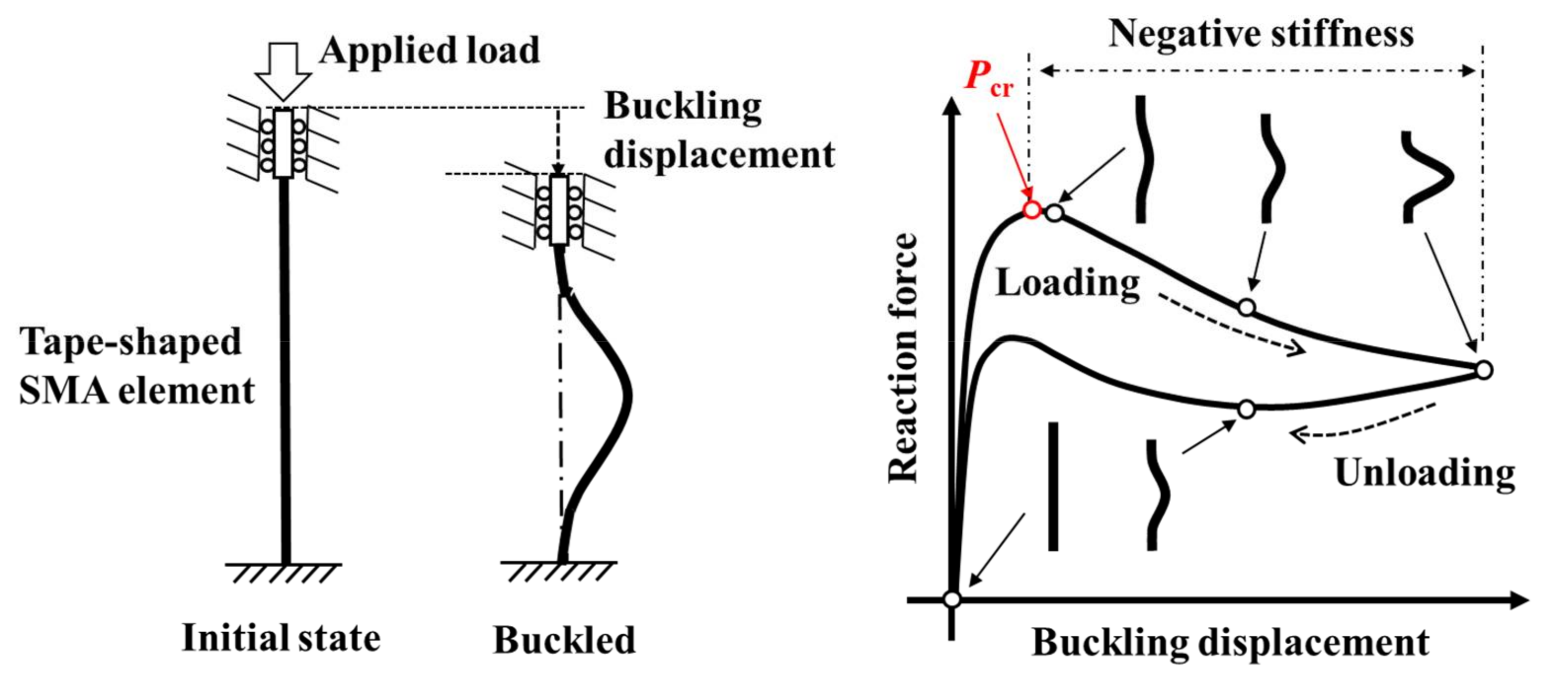
Figure 1. The relationship between reaction force and buckling displacement during buckling tests of a tape-shaped SMA element.
Actuators 11 00088 g001
Figure 2. Photograph and schematic drawing of the passive vibration isolator using tape-shaped SMA elements.
Actuators 11 00088 g002
Figure 3. The (a) flat tape-shaped and (b) convex tape-shaped Ti-Ni SMA elements fabricated in this study; and (c) the schematic drawing of the heat treatment method for producing tape-shaped Ti-Ni SMA elements.
Actuators 11 00088 g003
Figure 4. The stress–strain curve of a heat-treated Ti-Ni SMA element with flat tape shape at 333 K.
Actuators 11 00088 g004
Figure 5. The schematic drawing of the buckling testing machine used in this study.
Actuators 11 00088 g005
Figure 6. Schematic drawings of two buckling directions for convex tape-shaped element.
Actuators 11 00088 g006
Figure 7. Three-dimensional model (3D model) of a convex tape-shaped SMA element used in the software, and the process of analysis of the buckling behavior of this tape-shaped SMA element.
Actuators 11 00088 g007
Figure 8. The stress–strain curve of heat-treated Ti-Ni SMA element with flat tape shape obtained by tensile test at 333 K and of the material model input into the software.
Actuators 11 00088 g008
Figure 9. The numerically obtained relationships between the reaction force and buckling displacement of the flat and convex tape-shaped SMA elements in each buckling direction.
Actuators 11 00088 g009
Figure 10. The experimentally obtained relationships between the reaction force and buckling displacement of the flat and convex tape-shaped SMA elements in each buckling direction.
Actuators 11 00088 g010
Figure 11. The schematic drawing of two types of buckling surface for a tape-shaped SMA element with curvature of the cross-section.
Actuators 11 00088 g011
Figure 12. The numerically obtained (a) stress distribution and (b) κ dependence of maximum stress on the obverse surface of each specimen for each buckling direction at the buckling deformation start point.
Actuators 11 00088 g012
Figure 13. The numerically obtained (a) stress distribution and (b) κ dependence of maximum stress on the reverse surface of each specimen for each buckling direction at the buckling deformation start point.
Actuators 11 00088 g013
Figure 14. The numerically obtained (a) stress distribution and (b) κ dependence of maximum stress on the obverse surface of each specimen for each buckling direction, when the buckling displacement is 3 mm.
Actuators 11 00088 g014
Figure 15. The numerically obtained (a) stress distribution and (b) κ dependence of maximum stress on the reverse surface of each specimen for each buckling direction, when the buckling displacement is 3 mm.
Actuators 11 00088 g015
Figure 16. The numerically obtained results and schematic drawings of the cross-sectional shape of the center of the material for forward and reverse buckling with κ = 0.08 mm−1 when the buckling displacement is 3 mm.
Actuators 11 00088 g016
Publisher’s Note: MDPI stays neutral with regard to jurisdictional claims in published maps and institutional affiliations.