1. Introduction
Smart materials responding to an external stimuli can be used to fabricate smart actuators for applications ranging from wearable technology to self-folding aerospace structures [
1,
2,
3]. Extensive research in robotics has been carried out to utilise such devices to address the common challenges faced by rigid robots such as adaptable locomotion within a complex environment and safe interaction with human beings [
4]. The emergence of soft robotics at the intersection of smart materials, advanced fabrication techniques, and computational design addresses these challenges by drawing inspiration from biological organisms [
5]. The structural design of biological organisms is composed of soft and hard materials, with associated synchronised neuromechanical control. In order to develop robots mimicking such organisms, flexible actuation to deliver continuous deformation and embodiment of stiffness modulation through environmental interaction are essential [
6]. The advent of additive manufacturing technologies, progress in material science, and advances in soft material simulation software support the design and fabrication of such complex metamaterial soft actuation structures.
Various smart actuators including pneumatic, magnetic, light-induced liquid crystalline elastomers, dielectric elastomers, SMPs, and SMAs have been developed to be entirely soft and provide compliant actuation [
4,
7]. Shape memory materials, including SMAs and SMPs, belong to the class of smart materials that can be programmed to memorise a geometric shape and posses the ability to recover that shape from large deformation by external stimuli. Extensive studies have been implemented on thermal or electro-active shape memory materials in their usage as an actuator for deformable structures [
8,
9,
10]. In this work, a composite actuator was fabricated using the SMP and SMA to achieve bending actuation by electrical heating methods. Four-dimensional printing technology was utilised in this study to provide the shape memory effect in the SMP. The SMA and SMP were considered as 4D materials for actuators utilising electrical actuation in the next phase of the 3D printing model [
11]. The strength-to-weight ratio of the SMA and stiffness modulation properties of the SMP were extensively exploited to fabricate smart actuators. However, the SMA was limited by a smaller actuation strain with a complex shape memory effect caused due to stress in addition to temperature, and the SMP possessed low recovery stress and conductivity in addition to a higher cost.
Recent studies have implemented composite structures by utilising the complementary behaviour of SMAs and SMPs [
9,
12]. Composites with a higher recovery force and stiffness modulation in the structure can be achieved in a small form factor by combining SMAs and SMPs. By having complementary stiffness behaviours between SMAs and SMPs, periodic actuators can be devised by having the SMP as the energy storing element and the SMA as the high energy density actuator. In comparison to other actuators, this union can be programmed to different configurations and employ fewer drive elements, and an array of them can form multimodal robots. A curved actuator having a 3D-printed SMP matrix with Nylon-12-based SMP filaments was embedded with electrically heated SMA wires having a memorised straight shape. Kang et al. [
11] demonstrated the bi-state actuation of this composite for valve application by analysing the effect of the volume fraction of the SMA and SMP. Researchers have proposed a thermomechanical constitutive model to predict the bending of an actuator with linearly actuating SMA wire in between resin-based SMP layers [
13]. The model was further validated, and the parameters were obtained by performing thermo-mechanical experiments. Another study demonstrated the application of shape memory composites in smart valves and tents by reinforcing straight SMA wires in a resin-based SMP matrix. Most of the studies performed designed the optimisation and estimation of the model parameters based on trial and error. In order to efficiently utilise the resources along with a reduction of the time, the design can be optimised by focusing on computational methods. Manzo et al. [
8] proposed an analytical and ANSYS model for a multi-layer smart joint with a linearly actuating SMA over an SMP layer. The model was utilised in proposing a joint for wing morphing and biological flight structures. A Fortran-run material sub-routine in the Abaqus simulation aided the design of the shape memory composite laminate to maximise the deflection under the given constraints [
14]. The model was intended to demonstrate its application in developing a locking mechanism and self-assembling structures. A rapid solar sail deployment mechanism was achieved by having electrically driven SMA wires. Mathematical models demonstrating the actuation mechanism were implemented for various configurations and compared with the experimental studies for deployment time and folds [
15]. A few earlier works fabricated multi-state SMC from epoxy resins and prestrained SMA wires [
16,
17]. Although these studies employed analytical modelling or experimental validation to demonstrate the applicability of the design, the high cost involved in the fabrication procedures and complicated numerical models restricted the usability for complex designs. The computational models were limited by time complexity and modelling the multiphysics as an overhead.
Based on the literature, apart from linear actuation for SMAs, there exists a gap in the research for analysing different morphologies of the shape memory effect. The SMA with a pre-curved memorised geometry was used in this study to obtain larger deformation with smaller bending strain. Four-dimensional printing fabrication techniques were explored to program the flat memorised shape in the SMP matrix. COMSOL Multiphysics simulation, Version 5.5 [
18], was utilised with an in-built material model for the SMA and an external C subroutine for the SMP to model the complex interactions. A generic workflow to devise such shape memory actuators in future designs and analysing the viability for periodic actuation was proposed in this study. The proposed model was validated by conducting the required experiments, and the number of parameters was restricted by only obtaining the properties, which largely affected the behaviour of the model. The study identified that the transition temperatures played an important role in the shape recovery and energy requirements of the composites. The proposed model can prevent unwanted consumption of materials and speed up the fabrication process thorough the design.
The paper is structured as follows.
Section 2 discusses the actuation mechanism of the SMC by describing the theoretical actuation of the SMA and SMP;
Section 2.1 explains the fabrication and material characterisation process of the SMC;
Section 2.2 discusses the COMSOL Multiphysics simulation of the SMC to obtain the deflection of the actuator with respect to temperature;
Section 3 validates the results of periodic actuation model (in COMSOL Multiphysics) with the results from physical actuation of the SMC;
Section 4 provides conclusive evidence that the proposed FEA model describes the behaviour of the SMC.
2. Materials and Methods
The theoretical actuation of the SMA provided here was based on the concepts from Lagoudas [
19]. The theoretical actuation of the SMP provided here was based on the concept presented in Hu et al. [
20]. In this study, the mechanical programming of the SMP was implemented by the FDM technique to fabricate flat memorised structures with minimum prestrain to exploit the shape memory behaviour of the SMP.
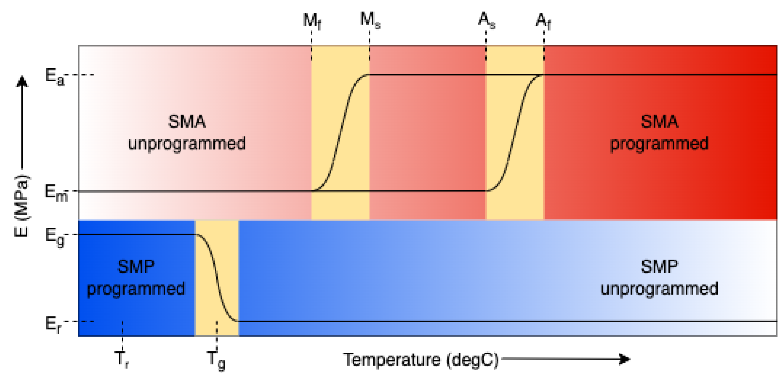
The design and fabrication of the SMC for periodic actuation was governed by the location of the transformation temperatures of the SMA and SMP. This study programmed the SMC to have the glass transition temperature of the SMP, , to be less than the martensite finish temperature of the SMA, , in order to possess the bi-state condition with a single one-way actuating SMA and SMP.
As can be seen from
Figure 1, the
of the SMP should be as low as possible relative to the
of the SMA for the desired behaviour to occur. Nevertheless, it should not be close to room temperature as the SMP loses the rigidity offered to the otherwise soft SMA in the structure. Apart from the transformation temperatures, the flexural stiffness and adhesion between the SMA and SMP play a critical role for the desired behaviour. The proposed actuation mechanism was based on the work presented by Taya et al. [
16]. The periodic two-way actuation of the SMC was realised by exploiting the viscoelastic nature of the SMP to store and dissipate strain energy and the memorised shape of both the SMA and SMP.
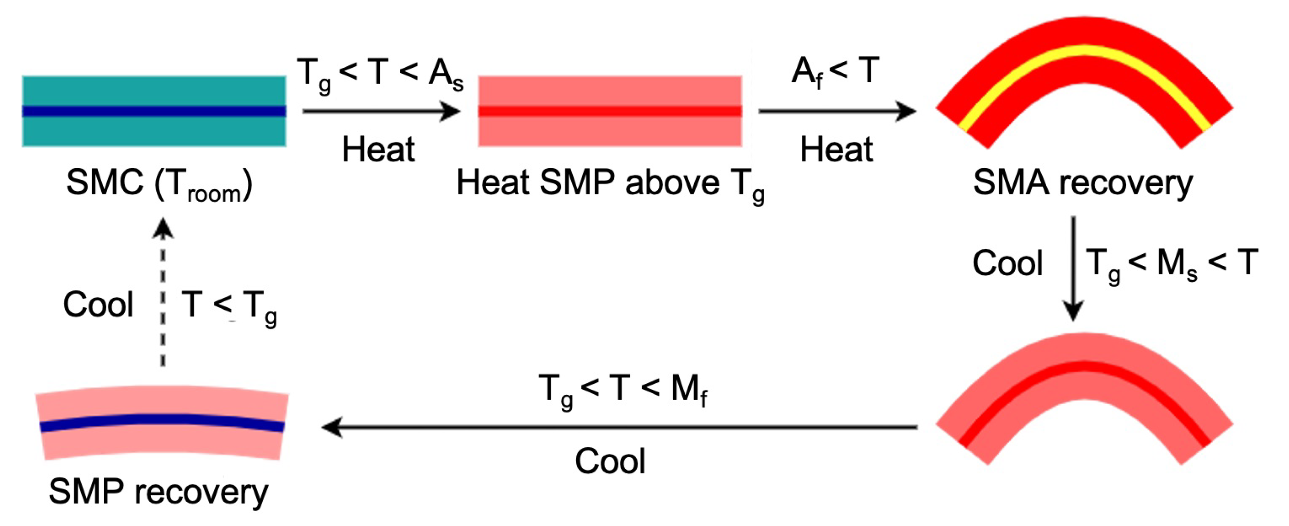
Figure 2 depicts the periodic working mechanism of the SMC due to the phase transformation and relative stiffness. The SMA had a memorised U shape, and the SMP had a memorised flat shape. The U-shaped SMA was prestrained by making it flat and placed in the SMC. At room temperature, as the SMP was in the memorised flat shape, the SMC remained flat. As the temperature was increased, the SMP transformed to the rubbery phase and became soft. When the temperature of the SMC reached the austenite start temperature of the SMA,
, it underwent a phase transformation from martensite to austenite and started to recover its memorised U shape. This induced strain in the SMP, and the strain energy was stored during the entire SMA transformation. When the SMC stared to cool, the rubbery phase SMP released the stored strain energy and worked against the stiffness of the austenitic SMA. When the temperature of the SMC was greater than the martensite start temperature of the SMA,
, the geometry remained the same as the soft SMP could not overcome the stiffness of the austenitic SMA. Upon further cooling to the martensite finish temperature of the SMA,
, the SMA transformed to martensite, thereby becoming soft. The antagonistic SMP could now work against the stiffness of the SMA in order to recover its memorised flat shape. The shape recovery occurred only till the rubbery phase became transformed to the glassy phase when the temperature fell below
. The process was repeated again to achieve periodic actuation by exploiting the shape recovery of the stiff SMA and storing the elastic energy in the rubbery SMP. The design of such an SMC was effective as the complementary behaviour of the SMA and SMP circumvented the presence of external biasing elements.
2.1. Fabrication and Material Characterisation
The fabrication of the SMC using additive manufacturing techniques and physical metallurgical process is explained in this section. In order to simulate and validate the FEA model, certain intrinsic parameters of the SMC needed to be determined. The following section provides a detailed explanation of the characterisation procedure of the SMC.
2.1.1. Sample Preparation
The popular choice of off-the-shelf SMA has a material constitution of Cu-Al-Ni or NiTi and possesses geometries such as wires, ribbon, pipes, foils, etc. A NiTi-based SMA ribbon, 1 mm thick and 5 mm wide, Fort Wayne Metals, and an SMA wire, 0.31 mm in diameter, Dynalloy Inc., was used in this study. The as-received SMA was cut into two pieces of the desired length to shape-set the curvature using heat treatment techniques. One of the heat-treated specimens cut to the desired length was used for determining the transformation temperatures from Differential Scanning Calorimetry (DSC). The other specimen was utilised for fabricating the SMC.
A polyurethane-based SMP 3D filament of 1.75 mm diameter, SMP Technologies Inc., was used in this study for rapid prototyping. The FDM printer, Cetus MK3 Extended by Tiertime Technology with a build volume of 180 mm × 180 mm × 280 mm, was employed to fabricate the specimen. The printer was set with a 0.4 mm-diameter nozzle having an extrusion temperature of 210 °C and a scanning speed of 20 mm/s with a 40 °C bed temperature. As the behaviour of the 3D-printed specimen was sensitive to raster orientation and possessed anisotropy [
20], the raster orientation was chosen by using the slicer, SciSlice, to be either along the longitudinal or transverse direction with a layer height of 0.3 mm. The phase transition behaviour and viscoelastic nature of the SMP were obtained by performing Dynamic Mechanical Analysis (DMA). The test was performed on three beam-like samples having average dimensions of 10 mm length × 2.98 mm width × 1.42 mm thick with 5 layers of 100% infill and the raster orientation along the longitudinal direction. In order to characterise the mechanical elastic properties of the 3D-printed SMP such as Young’s modulus
E and Poisson’s ratio
, uniaxial tensile tests were performed according to the ASTM D638 Type I [
21] standard’s geometry and sample dimensions. Four dog-bone specimens having twenty-three layers of 100% infill with liquefier movement along the gauge direction were fabricated, and arithmetic mean values from them were recorded.
2.1.2. Shape Setting and Characterisation of the SMA
Most of the commercially available SMA actuators are pretrained to memorise a particular geometry. The parent phase of such actuators can be reprogrammed by the process of shape setting. In order to program the required curvature of the SMA ribbon or wire in the parent phase, heat treatment was performed. This process influences the transformation temperatures of the alloy and effective memorised curvature. The as-received alloy ribbon was initially at super-elastic austenite phase and had a memorised flat shape at room temperature. The as-received alloy wire was in the martensite state with a memorised straight shape at
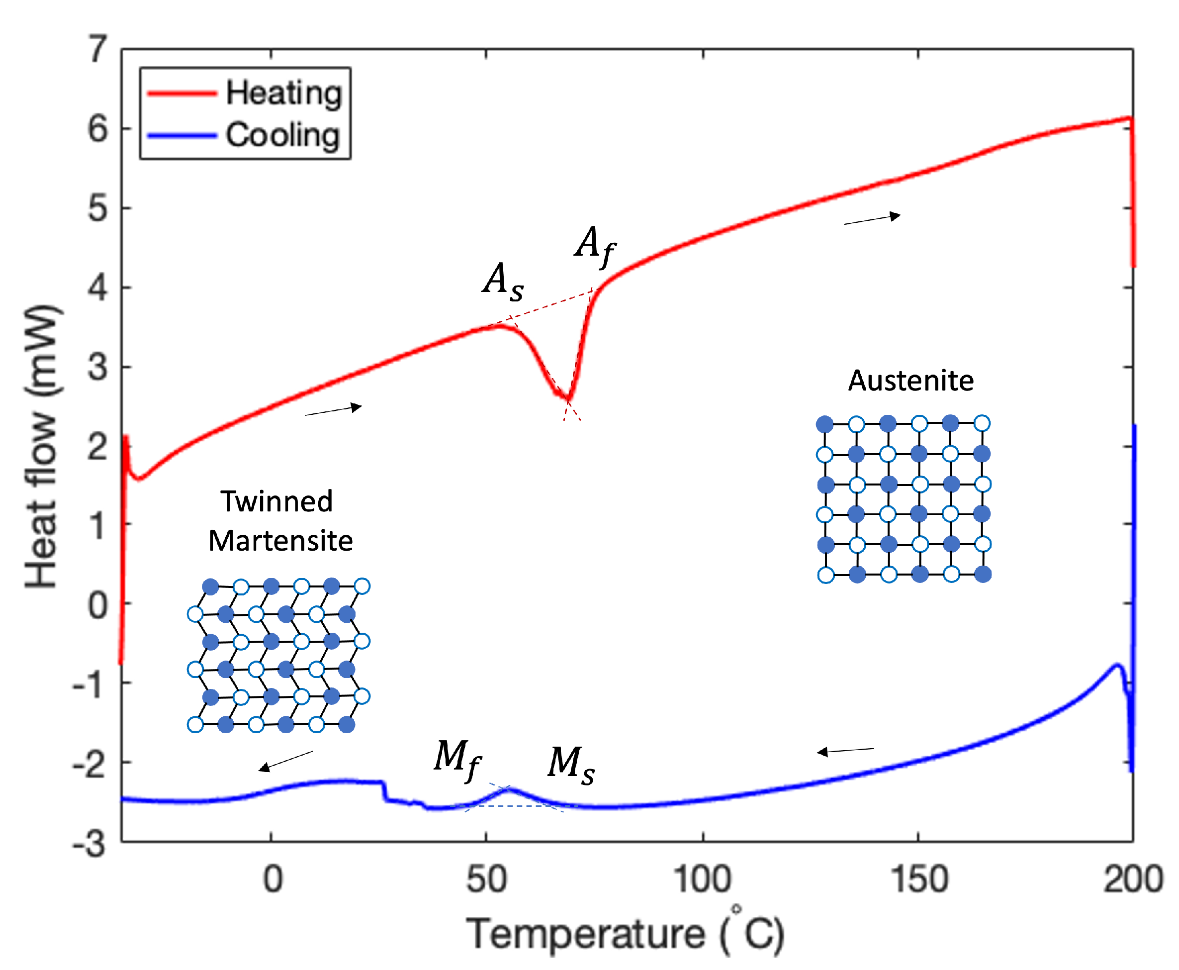
of 70 °C. The following steps illustrate the shape setting process of the alloy ribbon, and similar steps were executed for shape setting the alloy wire. First, the alloy was heat treated at 480 °C for 12 h to release any residual stress and quenched immediately to achieve the soft martensite phase at room temperature. The previous step was performed for the reproducibility of the experiment, but it is not strictly necessary. After that, it was set to the required curvature with the help of a metal fixture. Finally, the setup was placed in a furnace at 510 °C for about 10 min and immediately quenched. This reoriented the crystal structure and programmed the required curvature at the parent austenite phase. The latter step was repeated at least 6 to 8 times to uniformly shape-set the alloy. The shape setting procedure of the SMA altered the zero-stress phase transformation temperatures. The phase transformation temperatures of the shape-set NiTi SMA specimen were obtained from DSC. The prepared sample was kept inside a crucible in the form of wires and analysed for temperatures between −35 °C and 200 °C at a rate of 10 °C/min using the DSC instrument (Mettler Toledo DSC3). The plots from the DSC testing, shown in
Figure 3, provide the phase transformation temperatures obtained during heating and cooling. Here,
was obtained as 56.99 °C,
as 74.48 °C during heating,
as 66.42 °C, and
as 45.67 °C. Due to a limitation on the testing capability, properties such as thermal conductivity, resistivity, and stress gradient with respect to temperature were obtained from the literature [
22].
2.1.3. Characterisation of SMP
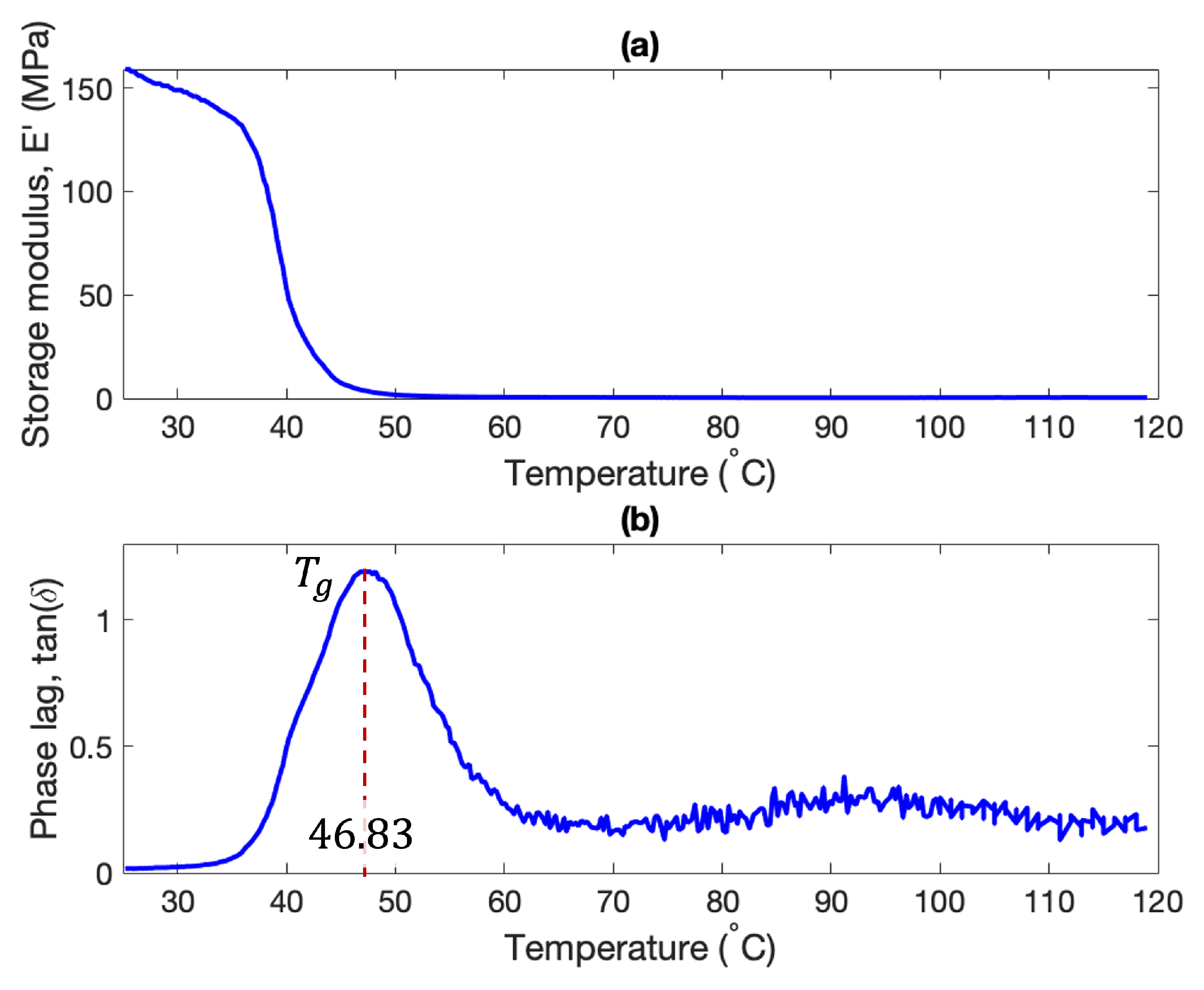
The DMA was performed using the DM analyser (Mettler Toledo TT-DMA). The test was setup with a 1 Hz frequency of force oscillation, and the sample was heated at a rate of 2 °C/min from 25 °C to 120 °C. The temperature-dependent viscoelastic properties, such as the storage modulus (
) and phase lag (
), obtained from the DMA test are shown in
Figure 4.
provides the elastic energy response of the material, and
indicates the ratio between the energy dissipated as heat and the energy stored elastically. As can be seen from
Figure 4, the storage modulus drastically reduced from 158 MPa in the glassy phase to roughly two orders of magnitude less at 0.3 MPa in the rubbery phase. The maximizing temperature of the
function represents the glass transition temperature
of the SMP, which in this case was attained at 46.83 °C. The mean value of all three DMA specimen was obtained as 44.59 °C, and this value was considered for modelling purposes. The tensile tests were executed on an MTS 9 Landmark (MTS Testing Solution) fit with a 250 kN load cell and mobile heating chamber. Three samples each were utilised for performing the test at room temperature and a high temperature of 70 °C. The average material properties obtained from the tests are reported in
Table 1. It can be seen that the Young’s modulus of the SMP in the rubbery phase increased by three orders of magnitude upon transformation to the glassy phase. Further, the Poisson’s ratio of the SMP increased from 0.41 in the glassy phase to 0.48 in the rubbery phase, displaying the increase in the incompressibility of the SMP. Due to a limitation on the testing capability, the thermal transport properties, such as the thermal conductivity and specific heat capacity at constant pressure, required for the COMSOL model were obtained from the literature [
14].
2.1.4. Fabrication of the SMC
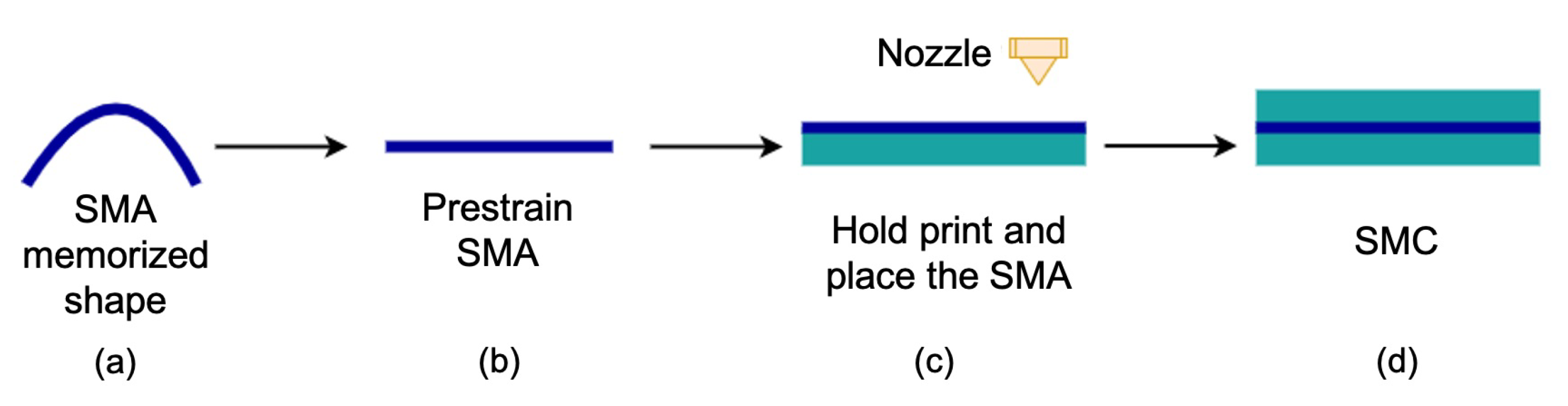
In this study, the SMC was fabricated to test and validate the model of periodic actuation by having a U-shape-set SMA in an SMP matrix.
Figure 5 depicts the process of fabricating the SMC. First, the SMA was prestrained to a straight shape using a mandrel or wire straightener. Care must be employed while prestraining, as it affected the recovery behaviour of the SMA. The SMP matrix was laid flat along the length and cut horizontally to generate the tool path by having a 0.3 mm layer thickness, a nozzle temperature of 210 °C, and a printing speed of 20 mm/s. In order to place the prestrained SMA wire, the middle layer was modified to have a groove along the length with the width equal to the diameter of the wire. The generated G-code had the provision to stop in between the print in order to place the wire. The prestrained SMA wire was placed and ensured to be flush with the printed surface. The print was then resumed to finish the rest of the SMP layers. In order to test the concept of the actuation mechanism and validate the COMSOL Multiphysics model, a sample of 80 mm length × 10 mm width × 1.2 mm thick was fabricated using this 3D printing setup.
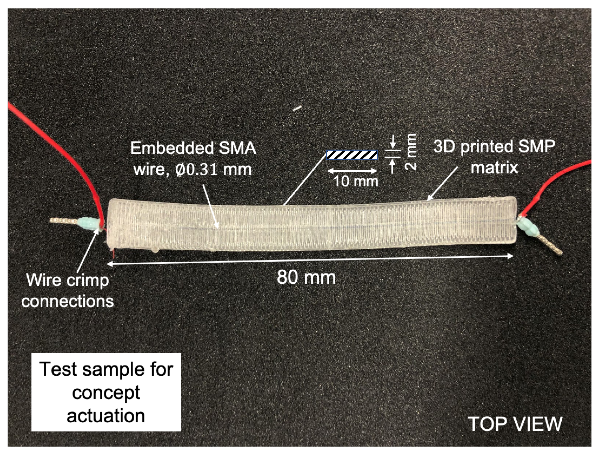
Figure 6 shows the labelled picture of the fabricated SMC along with the connecting wire. The U-shaped SMA wire was prestrained to a straight shape and placed inside the SMP matrix. The ends of the SMA wire were crimped to connect to the power source (Dr.Meter PS-3010DF). The deflection was captured using the Pointgrey Grasshopper machine vision camera, and the temperature was monitored using the Optris PI450 infra-red camera. The fabricated SMC was placed on the ground, and a constant output current of 2.2 A was provided by the power supply to heat the SMA using Joule heating to above the
temperature. The power supply was then turned off to decrease the temperature of the SMC. The deflection data with respect to time were obtained using the snapshots from the camera.
2.2. Modelling the Actuator
The design of the SMC actuator was carried out in the commercial FEA software, COMSOL Multiphysics, by simulating time-dependent studies. The applicability of the design workflow was demonstrated in COMSOL by running the actuator’s multiphysics interaction and capturing deformations.
2.2.1. Thermomechanical Constitutive Model: Shape Memory Alloy
The Lagoudas [
19] thermomechanical sub-routine of the SMA implemented in the Nonlinear Structural Materials Module of COMSOL Multiphysics [
23] was utilised for defining the phenomenological behaviour of the SMA domain. The constitutive model obtained input temperature field
T, total stress tensor
, and additional model parameters to calculate the explicit form of the Gibbs free energy density,
, to approximate the total strain,
, given by,
where
and
are the thermal and transformation strain tensor and
S is the compliance matrix averaged based on martensitic phase fraction (
). The above expression provides the constitutive relation in agreement with the Second Law of Thermodynamics. The model parameters obtained from DSC testing and the literature are provided in
Table 2. These parameters were necessary to define the required thermo-mechanical behaviour in COMSOL Multiphysics.
2.2.2. Thermomechanical Constitutive Model: Shape Memory Polymer
The constitutive relationship model for the phase transformation behaviour based on the irreversible thermodynamic process provided in Bodaghi et al. [
24] is reviewed here. The total strain,
, based on the additive strain assumption is provided as,
where
is the thermal expansion co-efficient for thermal strain,
,
is the total inelastic strain,
and
denote the elastic strains in the corresponding phases, and
is the volume fraction of the glassy phase in the SMP. The volume fraction of the glassy phase,
, at a given temperature,
T, is represented as trigonometric functions and DMA test fit parameters.
where
u and
v are the DMA test fit parameters,
and
are the highest and lowest temperatures of the fit data, and
is the glass transition temperature of the SMP. The total stress vector,
, from the Helmholtz free energy density in agreement with the Clausius–Duhem inequality is given as,
where total stiffness,
, can be expressed in terms of the compliance matrix,
S, as,
The compliance matrices,
and
, were calculated from the corresponding Young’s modulus
E and Poisson’s ratio
,
The evolution of the inelastic strain in the SMP when the material cools from the rubbery phase to the glassy phase or the recovery of the inelastic strain in the SMP when the material is heated above
is given as,
The recovery relation during heating provides current inelastic strain by implicit backward Euler integration as,
The evolution relation is then expressed as,
where
t provides the current time step value,
, and
I is the identity matrix. This provides a linear thermo-mechanical constitutive model for the glassy and rubbery phase given as,
where,
The first condition of Equation (
11) is for heating when
> 0, and the second condition is for cooling. The mean value of the calibrated parameters for the trigonometric function of
obtained from fitting DMA test data are provided in
Table 2. The modelling parameters were provided as the input in the COMSOL external material subroutine.
2.2.3. Finite Element Model
The geometrically nonlinear multiphysics interaction of the SMC was modelled in COMSOL to study the complex deformation, and acts as a tool to support the design workflow of such complicated systems. The constitutive relationship of the SMP domain needs to be provided as an external stress–strain subroutine to COMSOL, similar to the procedure illustrated in Bodaghi et al. [
24].
The user-defined material subroutine was programmed using the C language and compiled as a dynamic link library to be provided as the external material model in COMSOL. The general stress–strain relation socket of the external material module was chosen, as the entire constitutive relations was programmed along with the calculation of the inelastic strain. The socket requires the second Piola–Kirchoff stress tensor and Jacobian update to be returned as the output in order to solve the structural mechanics problem. The SMP material model was operated in the additive strain approximation, and the SMA material model was forced to be operated in the small strain region for faster convergence. The thermal strain in the SMA and SMP domain was neglected as it would be negligible in comparison with the actuation strain [
14].
2.2.4. Validation of the User-Defined Material Model
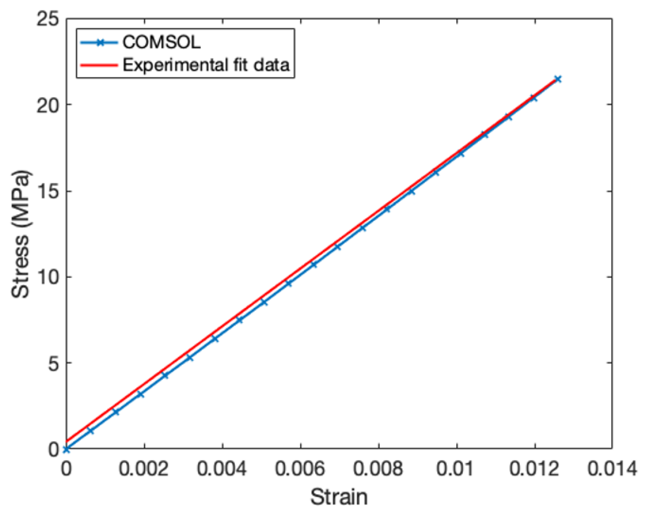
The accuracy of the user-defined material subroutine was determined by simulating the uniaxial tensile test. The CAD model of the tensile test specimen used for fabrication was imported and defined as the SMP material domain. The portion of tensile test specimen held by the wedges or clamped was neglected from the CAD model. One end of the specimens was applied a fixed constraint simulating the fixed head. The other end was applied a boundary load of 2330.95 N at room temperature and 17.43 N at 70 °C, simulating the final load applied by the moving head. Three observation points were created at the gauge section to extract the extensometer displacement value. A stationary study was set up to extract the true stress and strain values from the simulation. These values were compared with experimental data to determine the accuracy of the external material subroutine.
2.2.5. Validation of the Actuator Model
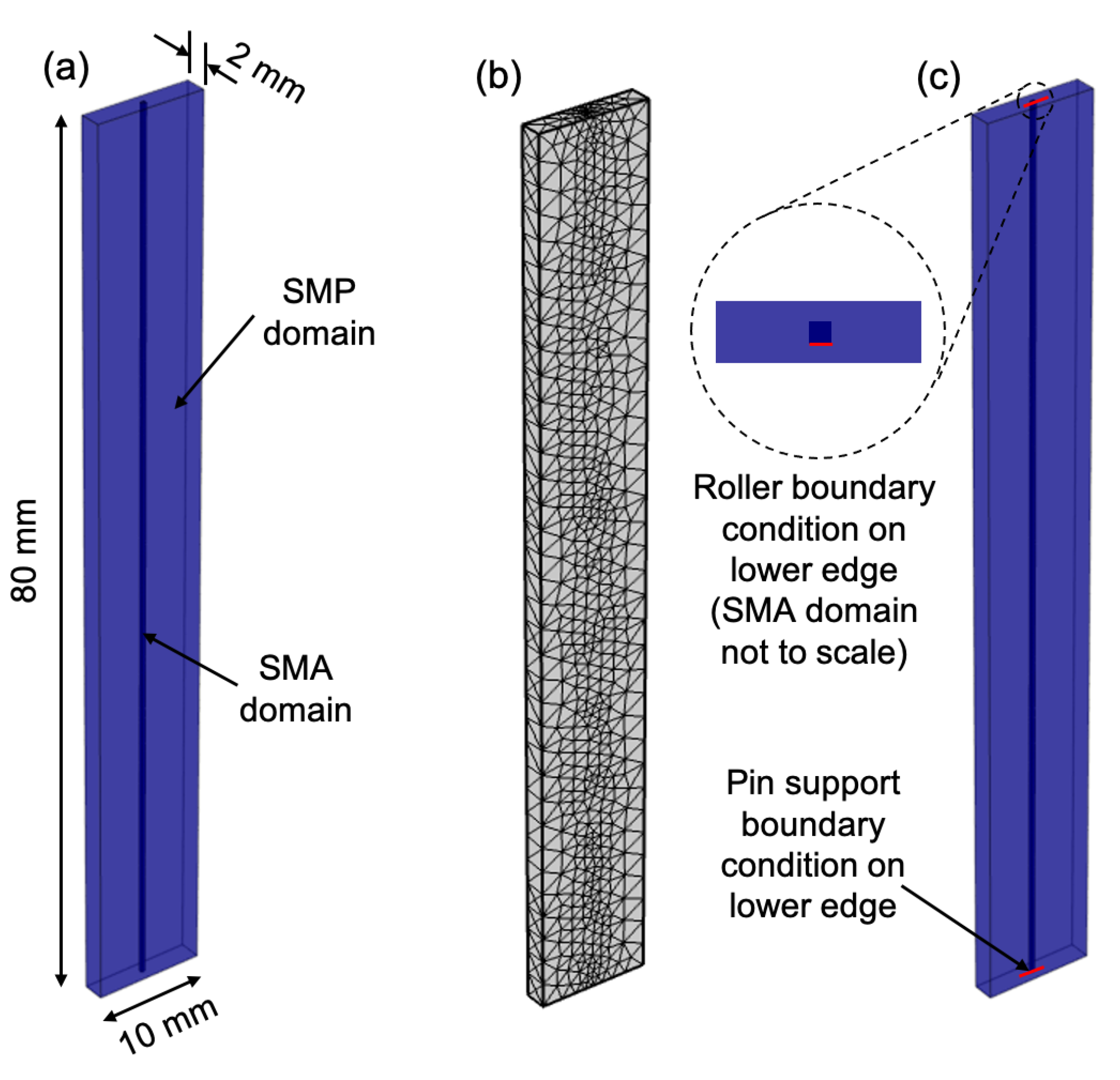
The SMA wire geometry modelled with a square cross-section having a straight shape was embedded at the centre of the flat SMP geometry. Continuity pairs were created at the interface between the two domains with the assumption of establishing the continuity in strain and temperature without causing delayering. The permanent shape of the SMA wire was provided in the form of initial strain as a function of temperature. Therefore, when
was reached, the initial strain ramped up to the shape setting bending strain upon complete transformation at
. In order to formulate the model workflow for designing the composite actuator, the multiphysics simulation model was condensed to isothermal assumptions, and complexities were added progressively. The isothermal assumption had the domain temperature interpolated between the set temperature values. During heating, the temperature was linearly increased from room temperature to 100 °C and linearly decreased to room temperature upon cooling. The solid mechanics interface was utilised to input the temperature and define the stress–strain relation of the SMA and SMP. The bending strain for the U-shape-set SMA of a 35 mm radius of curvature was provided by the
Initial Strain feature of
Shape memory alloy material module. The simulation study was set up to obtain the displacement of the midpoint over heating and cooling cycles in order to compare with the experimental results. The SMC was modelled as a beam having pin support on one end of the SMA domain and roller support on the other end as the boundary conditions. COMSOL automatically generates a finer mesh for both the SMA and SMP domains.
Figure 7 depicts the overall geometry, mesh, and boundary conditions. This study validated the isothermal domain simulation model with the experimental results and described the trend during the heating and cooling cycles.
3. Results and Discussion
3.1. Validation of the User-Defined Material Model
The user-defined SMP material subroutine was validated by simulating the uniaxial tensile test. The stress–strain relation of the simulation data was extracted and compared against the experimental data.
Figure 8 shows the good agreement between the simulation and experimental data at room temperature. As the SMP exhibited an elasto-plastic behaviour at room temperature, the strain value was limited close to 1% to demonstrate the behaviour of the actuator in the small strain linear region.
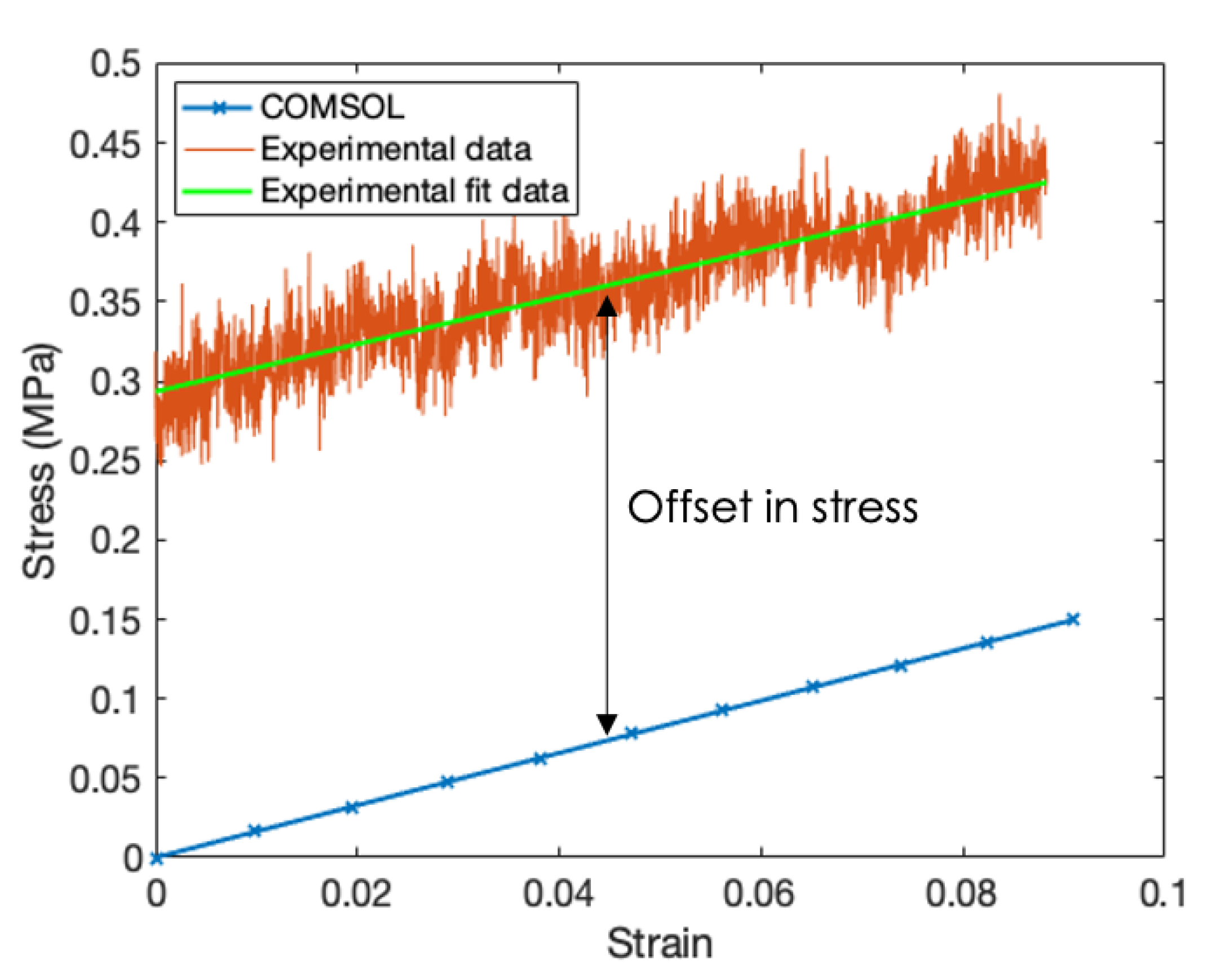
Figure 9 shows the good agreement of the trend in the stress with the strain between the simulation and experiment at 70 °C. It can be seen that the experimental data were noisy due to the high resolution of the load cell and the smaller load difference. The data were linearly fit, and the value of the slope was determined. The offset in the prediction of the stress by the simulation from the experimental data was due to the accumulation of thermal stress in the specimen as it was heated to the set temperature inside the chamber. This offset was taken into account in the simulation model as an external stress value. The result showed that the external SMP material model agreed well with the experimental results.
3.2. Validation of the Actuator Model
First of all, the bending stiffness of the SMA and SMP domain needed to be roughly estimated in order to interpret the actuation mechanism. Based on the model parameters provided in
Table 2, the bending stiffness of the SMA wire could range between 21.54 N mm
(
I = 7.696 × 10
mm
and
= 28 GPa) in the martensite and 60.02 N mm
(
I = 7.696 × 10
mm
and
= 78 GPa) in the austenite phase; the bending stiffness of the SMP in the rubbery phase can be 10.981 N mm
(
I = 6.667 mm
and
= 1.647 MPa) and in the glassy phase can be 11,114 N mm
(
I = 6.667 mm
and
= 1667.1 MPa).
The relative bending stiffness and portion of the SMP softened by the SMA largely influenced the bending or recovery characteristics of the SMC. The experimental setup had the actuator shown in
Figure 6 connected to a 3.3 V DC power supply providing 2.2 A of current. The setup was placed on the ground so that the composite bent upwards when it was actuated. The deflection of the actuator was obtained by post-processing the sequence of images captured by the RGB camera.
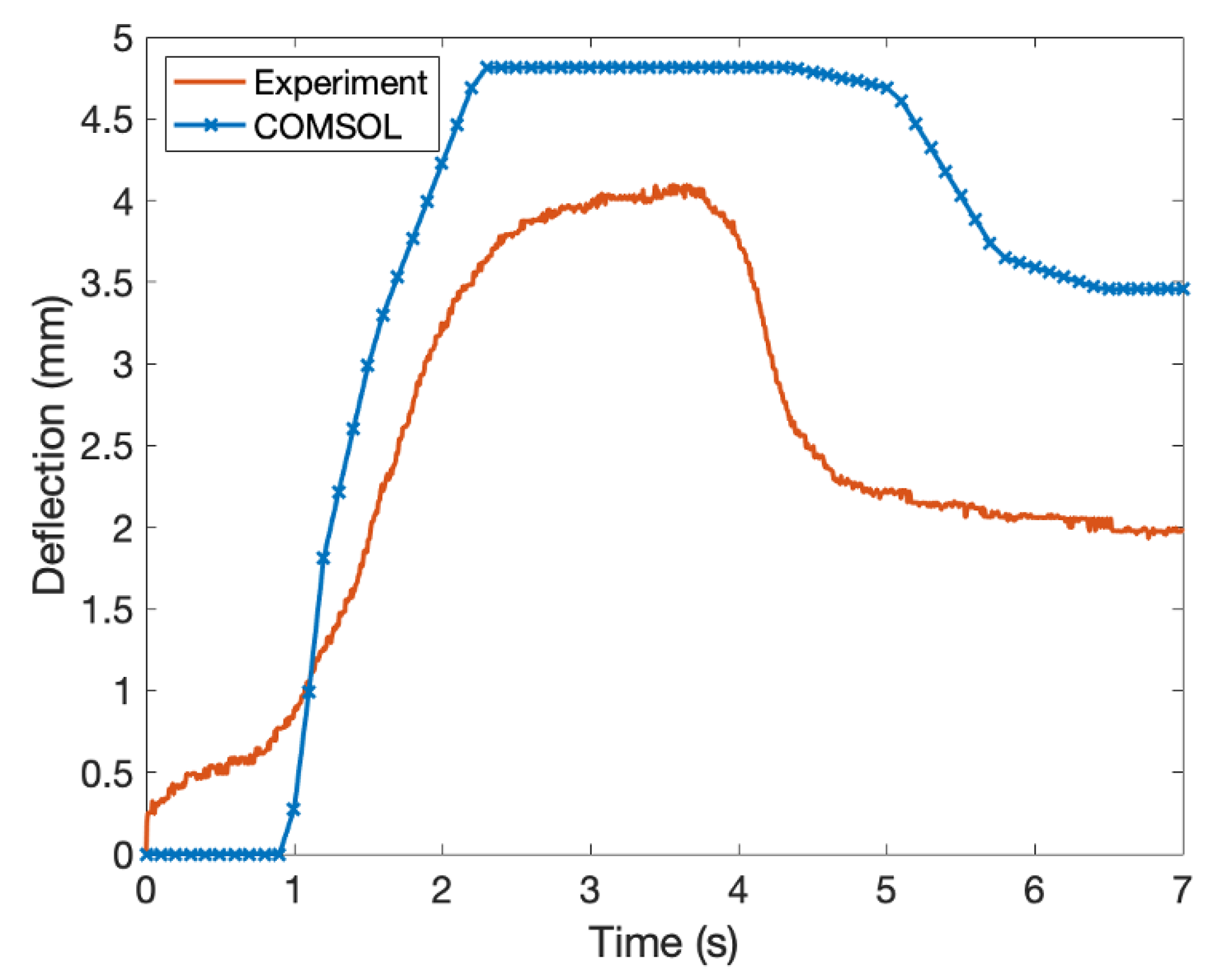
Figure 10 provides the mid-point deflection of the SMC over time for the experimental specimen and deflection predicted by the simulation model. It is noticeable that the prediction of the simulation model the during phase transformation of the SMA matched the trend observed in the experimental values. Although the simulation model predicted the max deflection with an error of 0.8 mm, certain discrepancies were present with the isothermal assumption.
The simulation model settled at a higher value of deflection as the entire volume fraction of the SMP was softened, whereas the experimental specimen had only a smaller a region of the SMP softened to the rubbery phase due to the low thermal conductivity and variation in the environmental condition. It can also be seen that the SMP was unable to recover its original shape due to the narrow difference in the transformation temperatures and relative stiffness. The chosen SMP material had a glass transition temperature of 44.59 °C, which was closer to the temperature of 45.67 °C. This means that a portion of the SMP would have already transformed to the glassy phase before the SMA became soft in the martensitic phase. This provided the SMP with little time to recover its memorised flat shape. The relative stiffness between the SMA and SMP also affected the shape recovery of the SMP as the bending stiffness of the SMP for the chosen sample in the rubbery phase, 10.981 N mm, was less than that of the bending stiffness of the SMA in the soft martensite phase, 21.54 N mm. Further, the FEA model was exploited to study the viability of the periodic actuation and parametric studies, e.g., increasing the number of SMA wires inside the SMC.
3.3. Periodic Actuation
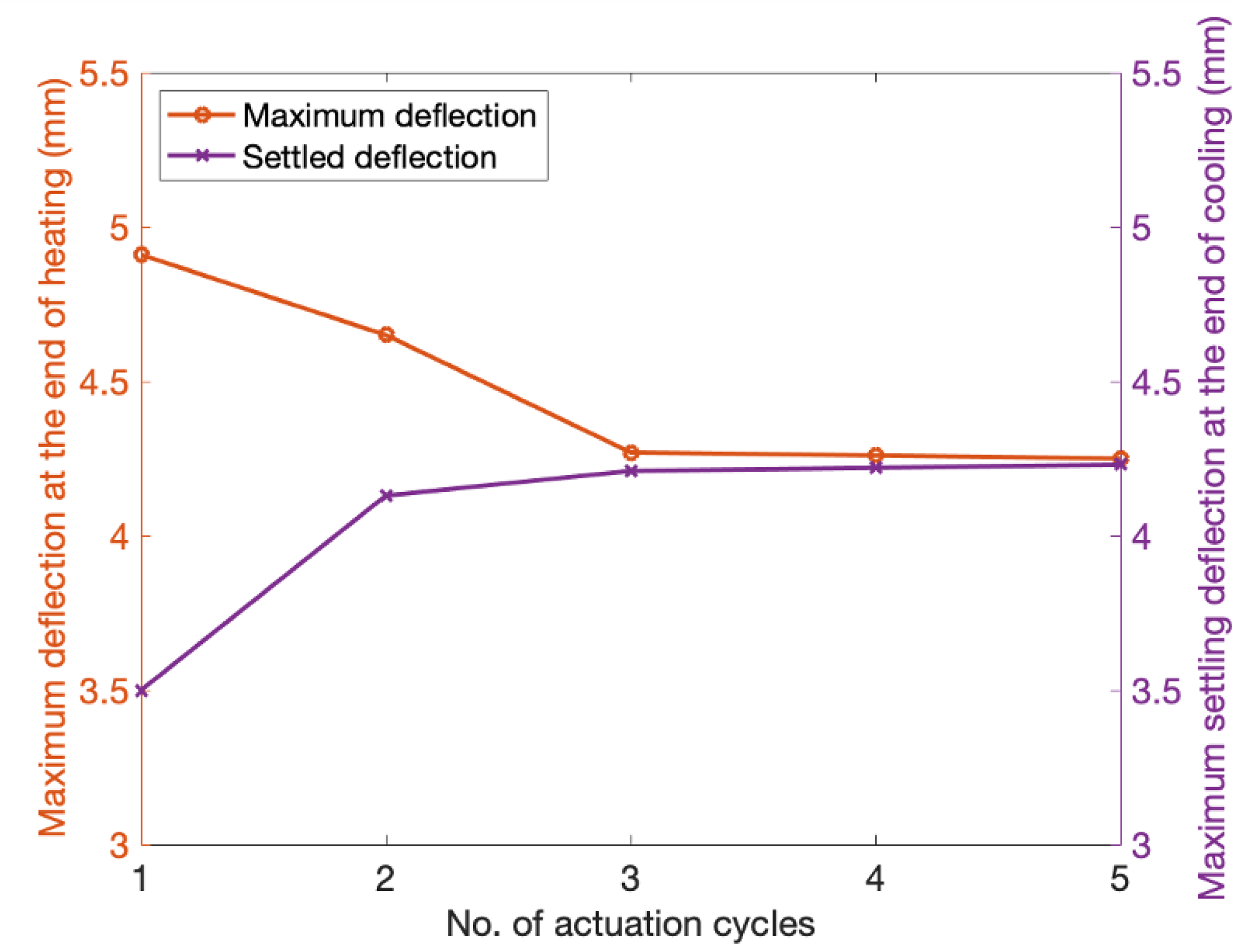
Figure 11 demonstrates the periodic actuation behaviour of the SMC with one SMA wire. The maximum deflection was obtained in the first cycle, and a decreasing trend was observed for the subsequent actuation cycles. On the contrary, the settled deflection at the end of the cooling for each actuation cycle increased and saturated after four actuation cycles. It can be seen from
Figure 11 that the effective amount of actuation decreased for the given geometry. This showed that the actuator was not viable for periodic actuation after five actuation cycles. The relative stiffness of the rubbery phase SMP and the narrow temperature difference present between
and
made the actuator inapplicable after five actuation cycles. The sudden decrease in the maximum deflection obtained for the initial actuation cycles was because the prestrain stored in the SMP during the previous cycle was partially recovered before the SMA transformed into austenite. This recovery happened till the SMA wire completely transformed to austenite. The SMA was required to perform additional work to resist the shape recovery due to the stored strain in addition to the stiffness of the rubbery phase SMP. Appropriate geometric dimensions and material parameters are critical in order to achieve periodic actuation. The developed actuator after the sequence of optimisation in the design put together as multiple components can serve as fingers for a robotic gripper end effector. The individual actuator with onboard electronics and control implementation can also be considered as an inchworm robot for navigating complex environments.
3.4. Effect of Increasing the Volume Ratio of the SMA Wire
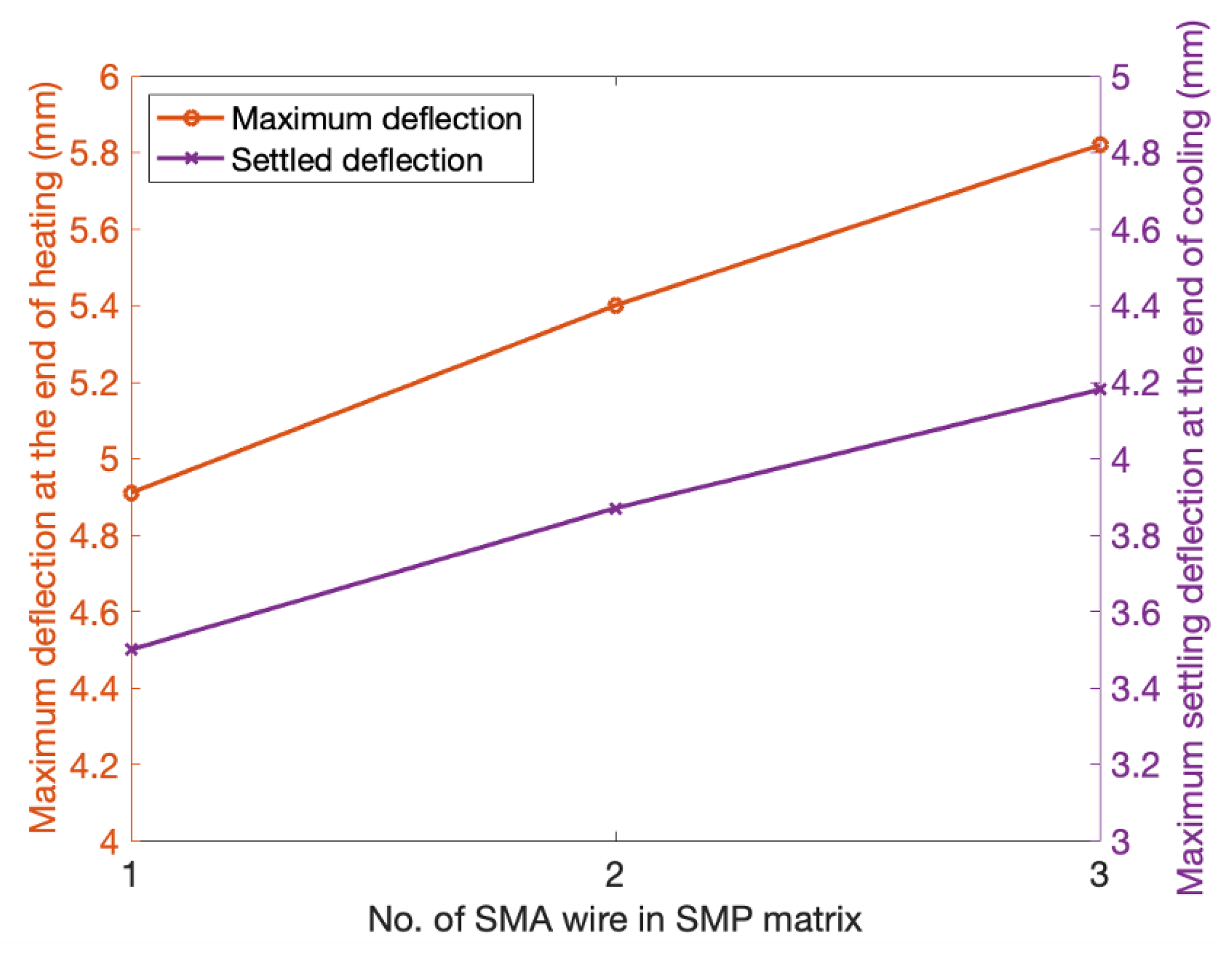
Figure 12 shows the effect of increasing the volume ratio of the SMA wires in the SMC on the maximum and settled deflection at the end of one cycle of actuation. There was a linearly increasing trend in the maximum and recovered deflection. The maximum deflection increased with the addition of another SMA wire because of the combined stiffness of two or more SMA wires in the SMC. The addition of the SMA wires increased the recovery stiffness that needed to be overcome by the soft rubbery phase SMP.
Figure 12 shows that the deflection settled at the end of each cooling cycle increased for an increased volume ratio of the SMA. Although providing a solid proof of concept for the use of SMC composite actuators, we expect the tunable performance profile of the actuator to be more fully exploited when co-designed with more complex morphologies.
3.5. Reflections from the Experiment
The shape recovery of the SMC was influenced by the difference between the and temperatures. Thus, a numerical study was essential to choose appropriate characterizing temperatures. Although it was essential to have an increased difference in temperature between and , there was an upper limit on the temperature that the SMP could be exposed to before the breakdown of the polymer chains occurred. This is critical while choosing the transformation temperatures of the SMA, as it can save on the energy consumption.
Fabricating the SMC using additive manufacturing techniques and handling thin SMA wire requires care and attention. The SMA wire needs to be slowly deformed along the plane of bending without rotating the wire to achieve appropriate deformation. Care must be employed to not create bumps as it might destroy the subsequent printing layers. It is advisable to have a fixture or jig to be accommodated with the printing bed in order to make this process easier. The adhesion of the SMA with the SMP is important for proper force and heat transfer. Increasing the bed temperature is helpful, but appropriate surface treatment methods are necessary for proper adhesion. The extrusion process of 3D printing causes localised heating of the SMA wire, which can induce phase transformation. This is undesirable as it can damage the composite while printing occurs, thereby discarding the specimen. Therefore, firmly fixing the SMA wire using crimps or a fixture on the printing bed and separate cooling of the wire are helpful.
4. Conclusions
The main objective of this research was to design a bi-state shape memory material composite soft actuator that combined the strengths of the SMA and SMP and provided a tunable performance profile. Experimentation was used to generate a working model in COMSOL Multiphysics, including understanding of the shape memory properties and actuation mechanism, material characterisation, model setup in COMSOL, and proof of concept testing.
The feasibility of the SMC was studied by (i) analysing the shape recovery, (ii) examining the longevity of the periodic actuation, and (iii) evaluating the effect of increasing the number of SMA wires to create a tunable actuating structure. Our results demonstrated the above objectives.
The feasibility of the design was validated through experiments and simulations with COMSOL Multiphysics. The relative stiffness between the SMA and SMP largely influenced the bi-state condition of the SMC. This is important to consider while designing such actuators because a large bending stiffness of the SMA may cause delayering of the specimen and loss in recovery of the shape of the SMP. Furthermore, the viability of the periodic actuator studied through the simulation showed higher deflection during the first cycle of actuation, as there was no stored inelastic strain present in the SMP that needed to be overcome by the SMA. This is critical because in the subsequent actuation cycles, the SMP lost its shape fixity and displayed reduced actuation. Although this served as a limitation on the periodic nature of the SMC, it can be improved by programming the SMP to have lower and the same order of bending stiffness as the SMA wire. The effect of increasing the number of SMA wires in the SMC is considerable and particularly useful for designs requiring a faster heating rate and larger deflection. However, this reduces the robustness of the actuator, as it results in the reduced shape recovery of the SMP.
Additional work can model a more realistic simulation of the real-world operating conditions. Rigorous experimental characterisation testing can be performed to obtain the thermo-mechanical properties of the conductivity for the SMP and the stress influence coefficient of the SMA. Strip or foil SMAs may be able to circumvent the fabrication and heating problems we encountered. Further research holds the experimental and simulation studies for understanding the bistability and evolution of the shape during the thermal cycles of the actuator. This area for exploration will push the boundaries of shape-memory-based soft actuators.
Overall, the complex multiphysics interaction of the SMC presented the necessity for numerical FEA simulation to aid the design of such actuators. The proposed COMSOL Multiphysics workflow can help reduce the wastage of materials, accelerate the process of soft actuator design, and provide a path towards highly optimised composite SMC components.


