Modeling and Experimental Research of One Kind of New Planar Vortex Actuator Based on Shape Memory Alloy
Abstract
:1. Introduction
2. Mechanical Model of SMA Vortex Spring
2.1. The Constitutive Model of SMA Material
2.2. The Mechanical Model of PVA
- Based on the assumption of one-dimensional deformation, describe the deformation process of the SMA vortex spring, and set the material to have the same elastic modulus and maximum recoverable strain during tension and compression.
- All physical parameters of the material are the same in the deformation process.
- The material is pure bending strain and the cross-sectional shape remains unchanged.
- The strain caused by thermal expansion is much smaller than the elastic strain caused by torsion and the material phase change strain, so the third term in the equation is ignored.
- The length of the deformed section of the PVA remains unchanged.
3. Calculation of Driving Performance
- Each parameter in the initial state is represented by subscript 0. Temperature is lower than martensitic initial phase transition temperature, namely t0 < Ms torque T0 = 0. The volume fraction of martensite is φ0 = 1, the memory factor is η0 = 0, the strain angle is ψ0 = 0.
- Parameters in the pre-tightening stage are set as 1. Temperature t1 = t0 < Ms. The deformation angle of PVA under the pretightening torque T1 is ψ1:
- 3.
- The parameter in the in-use stage is set as subscript 2. Keep the temperature t2 = t0 < Ms, T2 = 0 after the preload torque is removed. After PVA recovered the elastic deformation, the residual deformation angle was ψ2:
- 4.
- The parameters of the excited output state are indicated by the subscript 3. When the temperature is increased to t3 > As, the PVA generates shape recovery and outputs torque and angular displacement, which are T3 and ψ3, respectively. Since the stress change is caused by the difference between the elastic modulus during the transformation from martensite to austenite, there are constraints:
4. Validations and Discussions
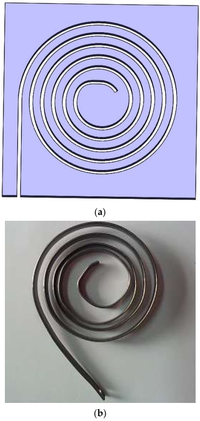
4.1. Design and Manufacture of PVA Sample
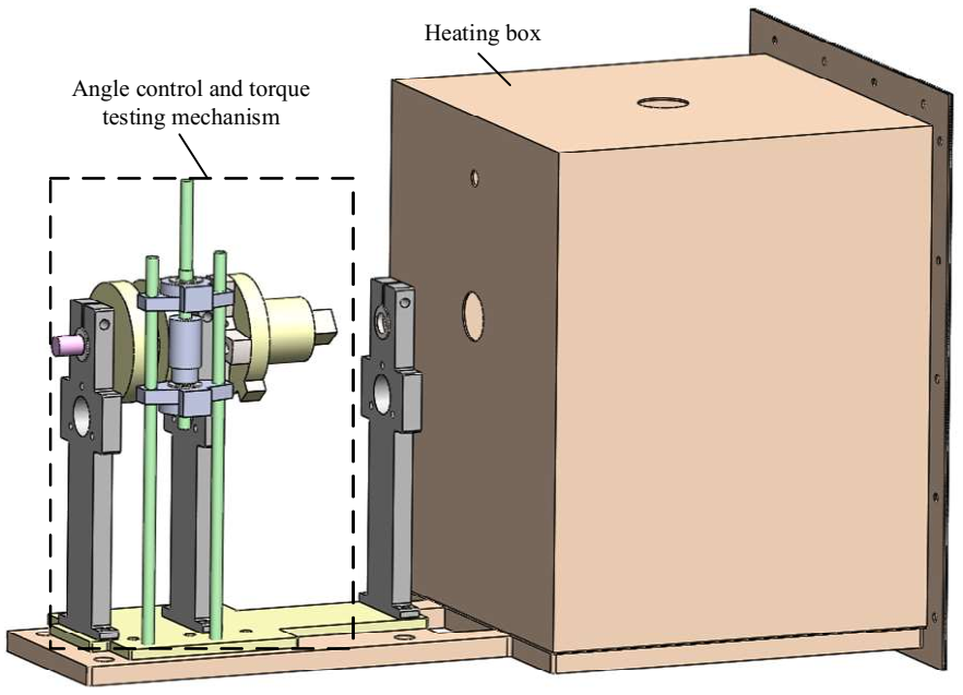
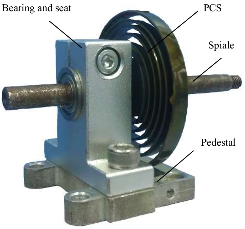
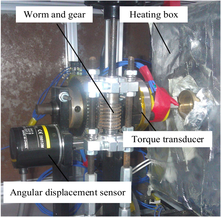
4.2. Test System Design and Construction
4.3. Experimental Validations
- Heat the PVA to 80 °C (above Af) in a free state, and slowly decrease the temperature to 20 °C (below Mf). Repeat more than three times to make sure the material is in full twin martensite state.
- Set the ambient temperature to 20 °C (lower than As), and preload the PVA to 270° according to the constraints of Equation (20), and the Tpre is 0.069 N·m. After the restraint is released, the residual strain is 214°. Connect the test device to the test system.
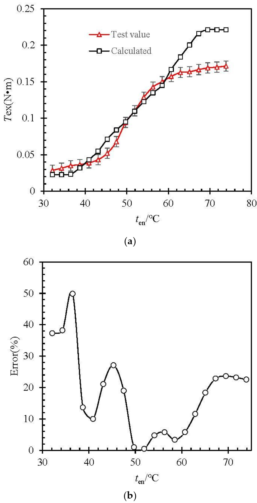
- The initial temperature of the water bath was set at 30 °C (lower than As), and the temperature is raised at 2 °C/min. The values of ten and Tex of the water bath are recorded. The values recorded in the test are compared with those calculated by Equations (33) and (34), and the results are shown in Figure 6.
- 4.
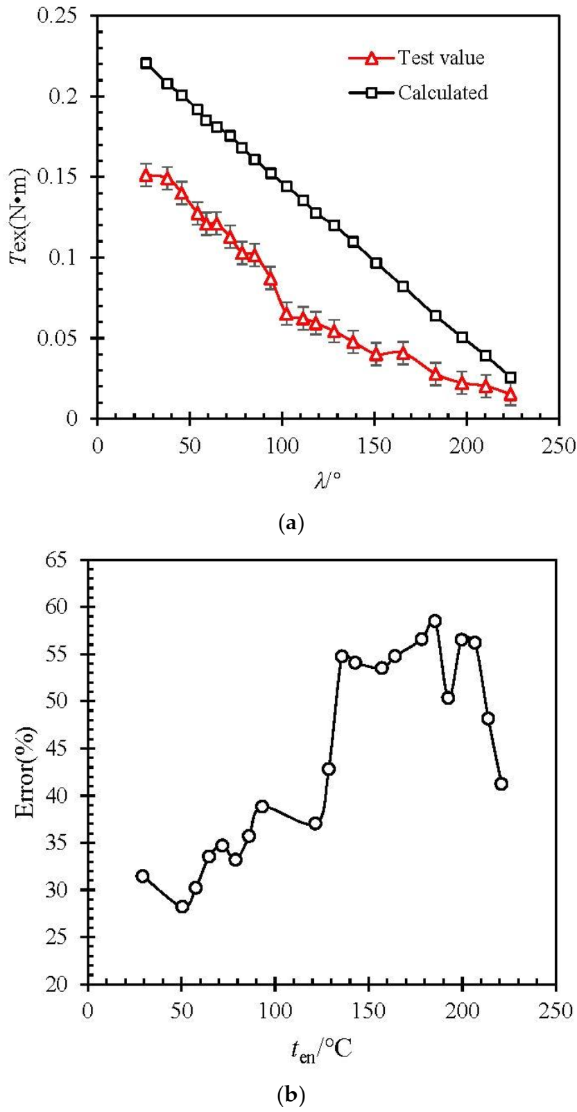
- When the torque output value Tex is stable, keep the excitation temperature ten unchanged (70 °C). Through the limit device, the angular displacement of the SMA vortex spring is increased by 3 (°)/s, and the value of the angular displacement λ and the torque output Tex are recorded. Compare the value of the test record with the value calculated according to Equations (33) and (34). The result is shown in Figure 7.
4.4. Error Discussions
- More experiments were conducted to increase the correction coefficient of the effect of spring vortex number on the mechanical model.
- The deformation model of large deformation and non-pure bending is established.
- It is no longer assumed that the stress and strain of each part of the strip are the same, but the distribution law of stress and strain is emphatically discussed.
- The influence of thermal expansion caused by temperature on the mechanical model is considered, especially when the number of vortex springs is large and the material length is long.
- The one-dimensional constitutive equation in the mechanical model is replaced by three-dimensional constitutive equation.
- The finite element method is used as the numerical calculation method to provide a verification means for the establishment of the theoretical model.
5. Conclusions
Author Contributions
Funding
Institutional Review Board Statement
Informed Consent Statement
Data Availability Statement
Conflicts of Interest
References
- Lambert, T.R.; Gurley, A.; Beale, D. SMA actuator material model with self-sensing and sliding-mode control; experiment and multibody dynamics model. Smart Mater. Struct. 2017, 26, 035004. [Google Scholar] [CrossRef]
- Park, S.; Hwang, D. An experimental study on precision positioning characteristics of shape memory alloy actuator. Microsyst. Technol. 2020, 26, 2801–2807. [Google Scholar] [CrossRef]
- Nizamani, A.M.; Daudpoto, J.; Nizamani, M.A. Development of faster SMA actuators. Shape Mem. Alloys Fundam. Appl. 2017, 105–126. [Google Scholar] [CrossRef] [Green Version]
- Mehrabi, H.; Aminzahed, I. Design and testing of a microgripper with SMA actuator for manipulation of micro components. Microsyst. Technol. 2020, 26, 531–536. [Google Scholar] [CrossRef]
- Khan, A.M.; Mansour, N.A.; Kim, Y.; Shin, B.; Ryu, B. Modeling of Novel Arc Shaped SMA Actuator. In Information Storage and Processing Systems; American Society of Mechanical Engineers: New York, NY, USA, 2021; Volume 84799, p. V001T09A004. [Google Scholar]
- Brinson, L. One-Dimensional Constitutive Behavior of Shape Memory Alloys: Thermomechanical Derivation with Non-Constant Material Functions and Redefined Martensite Internal Variable. J. Intell. Mater. Syst. Struct. 1993, 4, 229–242. [Google Scholar] [CrossRef]
- Tanaka, K. A thermomechanical sketch of shape memory effect: One-dimensional tensile behavior. Res. Mech. 1986, 18, 251–263. [Google Scholar]
- Liang, C.; Rogers, C.A. One-Dimensional Thermomechanical Constitutive Relations for Shape Memory Materials. J. Intell. Mater. Syst. Struct. 2013, 1, 207–234. [Google Scholar] [CrossRef]
- Zhou, B.; Wang, Z.Q.; Liang, W.Y. A micromechanical constitutive model of shape memory alloys. Acta Metall. Sin. 2006, 42, 919–924. (In Chinese). [Google Scholar]
- Zhou, B.; Liu, Y.J.; Leng, J.S. A macro-mechanical constitutive model of shape memory alloys. China Ser. G 2009, 7, 998–1006. [Google Scholar] [CrossRef]
- Wang, W.; Liu, Y. Structure Design and Research of Dexterous Finger based on the SMA Driver. In IOP Conference Series: Materials Science and Engineering; IOP Publication: Bristol, UK, 2018; Volume 439, p. 032078. [Google Scholar]
- Zhang, Q.; Tang, B.; Cai, J.; Yang, R.; Feng, J. Development and experimental verification of an adaptive structure for phased antenna array using SMA bunch. Eng. Struct. 2020, 225, 111293. [Google Scholar] [CrossRef]
- Kalra, S.; Bhattacharya, B.; Munjal, B.S. Design of shape memory alloy actuated intelligent parabolic antenna for space applications. Smart Mater. Struct. 2017, 26, 095015. [Google Scholar] [CrossRef]
- Pan, X.; Zhang, Y.; Lu, Y.; Yang, F.; Yue, H. A reusable SMA actuated non-explosive lock-release mechanism for space application. Int. J. Smart Nano Mater. 2020, 11, 65–77. [Google Scholar] [CrossRef]
- Wang, Y. Future Prospects of Space Robots. In Space Robotics; Springer: Singapore, 2021; pp. 353–363. [Google Scholar]
- Bian, K.; Zhou, C.; Zhao, F.; Wu, Y.; Xiong, K. Investigation of a shape memory alloy releasable mechanism applied in space environment. Int. J. Appl. Electromagn. Mech. 2020, 64, 393–401. [Google Scholar] [CrossRef]
- Yu, D.; Zhang, B.M.; Jinl, X. Structural Design Method of Rotation Gear Actuated by Shape Memory Alloys. J. Mech. Eng. 2010, 14, 91–94. (In Chinese). [Google Scholar] [CrossRef]
- Yang, K. Research and Application of New Inserted Shape Memory Alloy Actuators. IEEE Trans. Ind. Electron. 2010, 57, 2845–2850. [Google Scholar] [CrossRef]
- Kotb, Y.; Elgamal, I.; Serry, M. Shape Memory Alloy Capsule Micropump for Drug Delivery Applications. Micromachines 2021, 12, 520. [Google Scholar] [CrossRef] [PubMed]
- Barbarino, S.; Ameduri, S.; Pecora, R. Wing chamber control architectures based on SMA: Numerical investigations. In International Conference on Smart Materials and Nanotechnology in Engineering; International Society for Optics and Photonics: San Diego, CA, USA, 2007; Volume 6423, p. 64231E. [Google Scholar]
- Zhang, W.; Zhang, C.; Liu, B.; Zhang, B.; Wang, L. Research on Variable Sweepback Angle of Winglet Driven by Shape Memory Alloy. In IOP Conference Series: Materials Science and Engineering; IOP Publication: Bristol, UK, 2020; Volume 926, p. 012014. [Google Scholar]
- Xu, L.; Fu, Z. Multifield coupled analysis for a harmonic movable tooth drive system integrated with shape memory alloys. Appl. Math. Model. 2019, 69, 493–505. [Google Scholar] [CrossRef]
- Borboni, A.; Aggogeri, F.; Pellegrini, N.; Faglia, R. Innovative modular SMA actuator. In Advanced Materials Research; Trans. Tech. Publications Ltd.: Zurich, Switzerland, 2012; Volume 590, pp. 405–410. [Google Scholar]
- Sun, J. Parameters design of spiral spring in solar panel. Spacecr. Eng. 2000, 9, 37–43. (In Chinese). [Google Scholar]
- Bucolo, M.; Buscarino, A.; Famoso, C. Control of imperfect dynamical systems. Nonlinear Dyn. 2019, 98, 2989–2999. [Google Scholar] [CrossRef]

| r1 (mm) | N | tr (mm) | l (mm) | h/(mm) | b (mm) |
|---|---|---|---|---|---|
| 6 | 4.5 | 3.5 | 390 | 0.8 | 4.5 |
| Ms/°C | Mf/°C | As/°C | Af/°C | EM/GPa | EA/GPa |
|---|---|---|---|---|---|
| 27 | 22.5 | 35 | 55 | 22 | 50 |
| CM/MPa·(°C)−1 | CA/MPa·(°C)−1 | /MPa | /MPa | /% | |
| 8 | 17 | 35 | 150 | 5.5 | |
| b/mm | h/mm | Rs/mm | p/mm | n0 |
|---|---|---|---|---|
| 6.5 | 0.83 | 3 | 5 | 3.5 |
Publisher’s Note: MDPI stays neutral with regard to jurisdictional claims in published maps and institutional affiliations. |
© 2021 by the authors. Licensee MDPI, Basel, Switzerland. This article is an open access article distributed under the terms and conditions of the Creative Commons Attribution (CC BY) license (https://creativecommons.org/licenses/by/4.0/).
Share and Cite
Kong, X.; Gu, Y.; Wu, J.; Yang, Y.; Shen, X. Modeling and Experimental Research of One Kind of New Planar Vortex Actuator Based on Shape Memory Alloy. Actuators 2022, 11, 8. https://doi.org/10.3390/act11010008
Kong X, Gu Y, Wu J, Yang Y, Shen X. Modeling and Experimental Research of One Kind of New Planar Vortex Actuator Based on Shape Memory Alloy. Actuators. 2022; 11(1):8. https://doi.org/10.3390/act11010008
Chicago/Turabian StyleKong, Xiangsen, Yilei Gu, Jiajun Wu, Yang Yang, and Xing Shen. 2022. "Modeling and Experimental Research of One Kind of New Planar Vortex Actuator Based on Shape Memory Alloy" Actuators 11, no. 1: 8. https://doi.org/10.3390/act11010008
APA StyleKong, X., Gu, Y., Wu, J., Yang, Y., & Shen, X. (2022). Modeling and Experimental Research of One Kind of New Planar Vortex Actuator Based on Shape Memory Alloy. Actuators, 11(1), 8. https://doi.org/10.3390/act11010008


