
A Computational Geometric Parameter Optimization of the Thermomechanical Deicing Concept


Abstract
:1. Introduction
1.1. A Brief Look into Deicing Systems
1.2. Thermomechanical Deicing Concept Using an SMA Actor
2. Materials and Methods
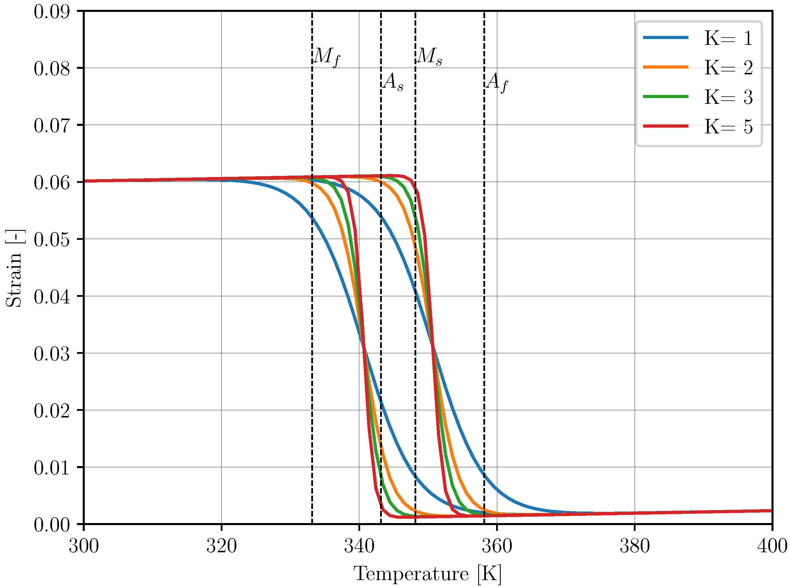
2.1. Shape Memory Alloy Material Model
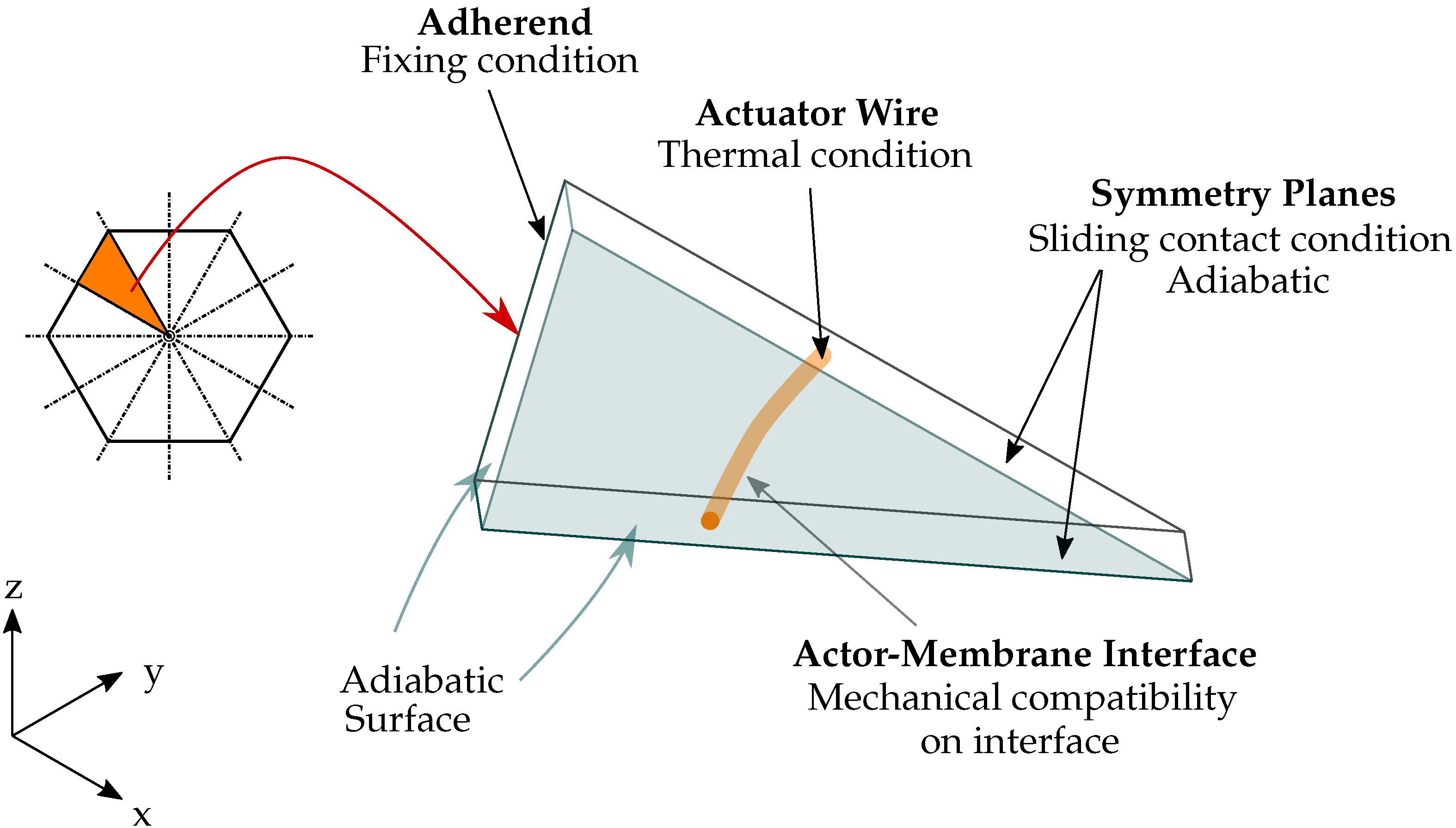
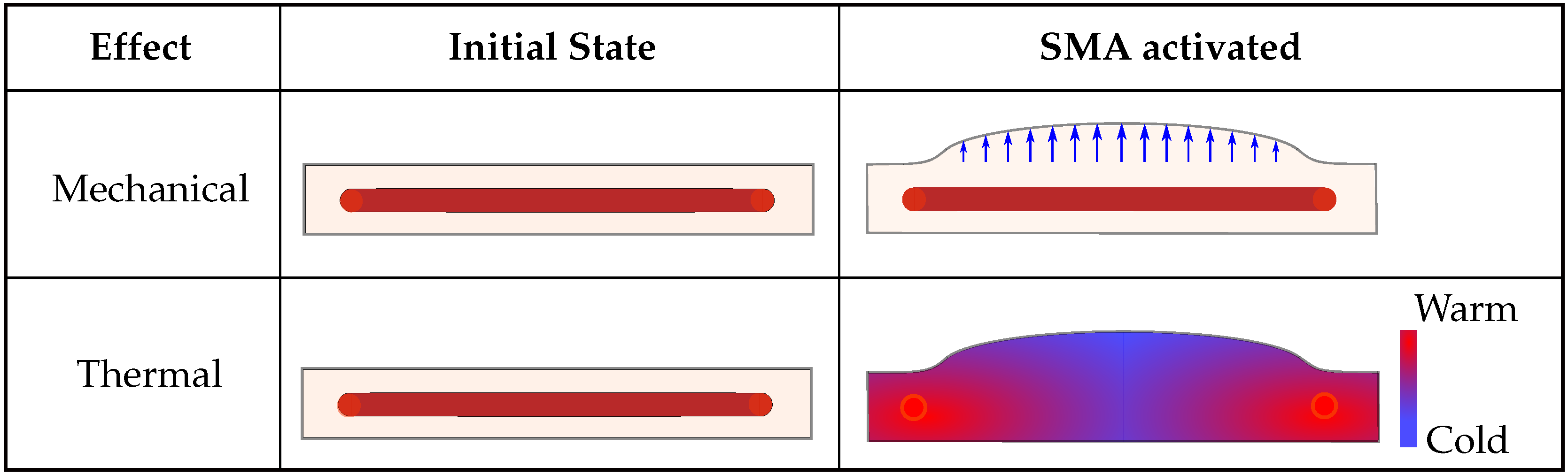
2.2. FEM Model of the Deicing Concept
3. Results
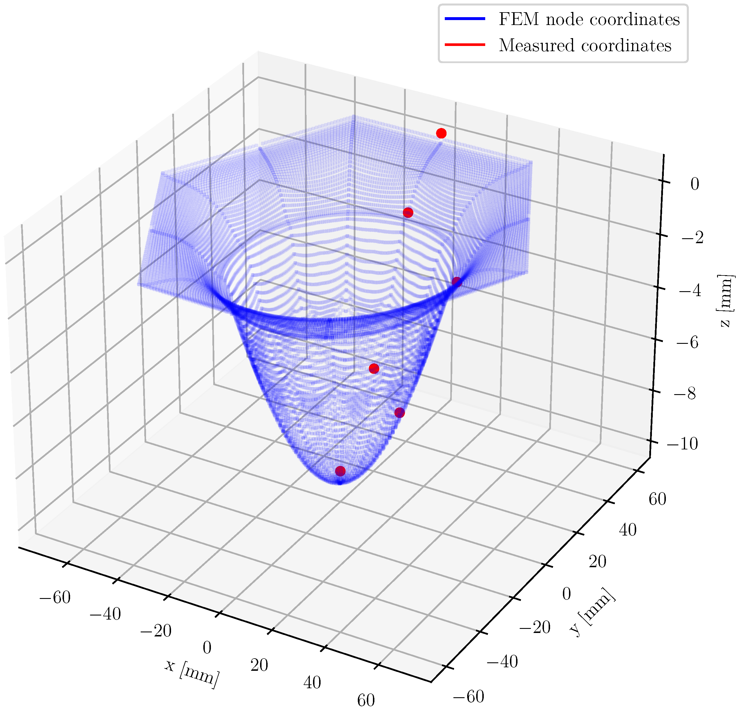
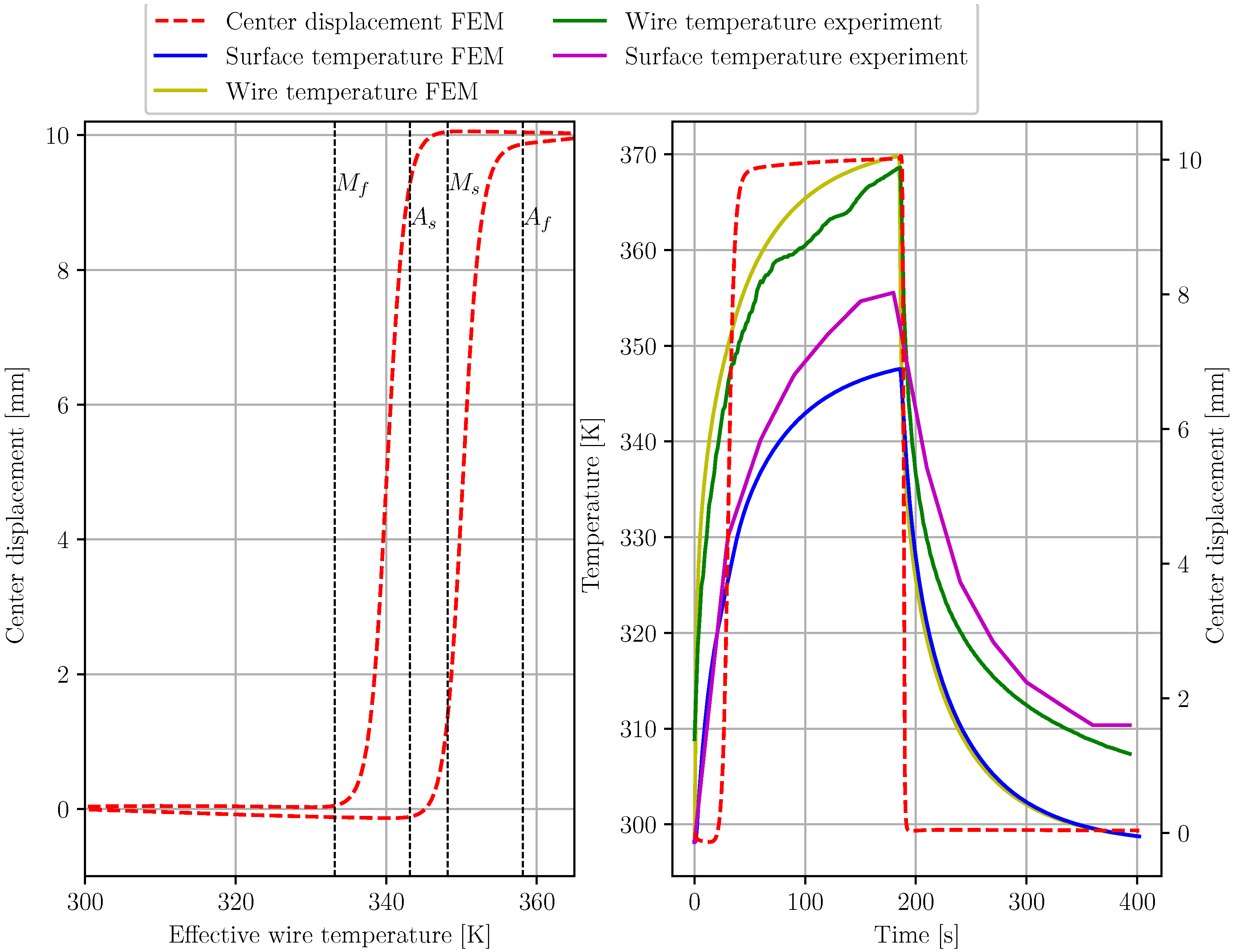
3.1. Model Validation
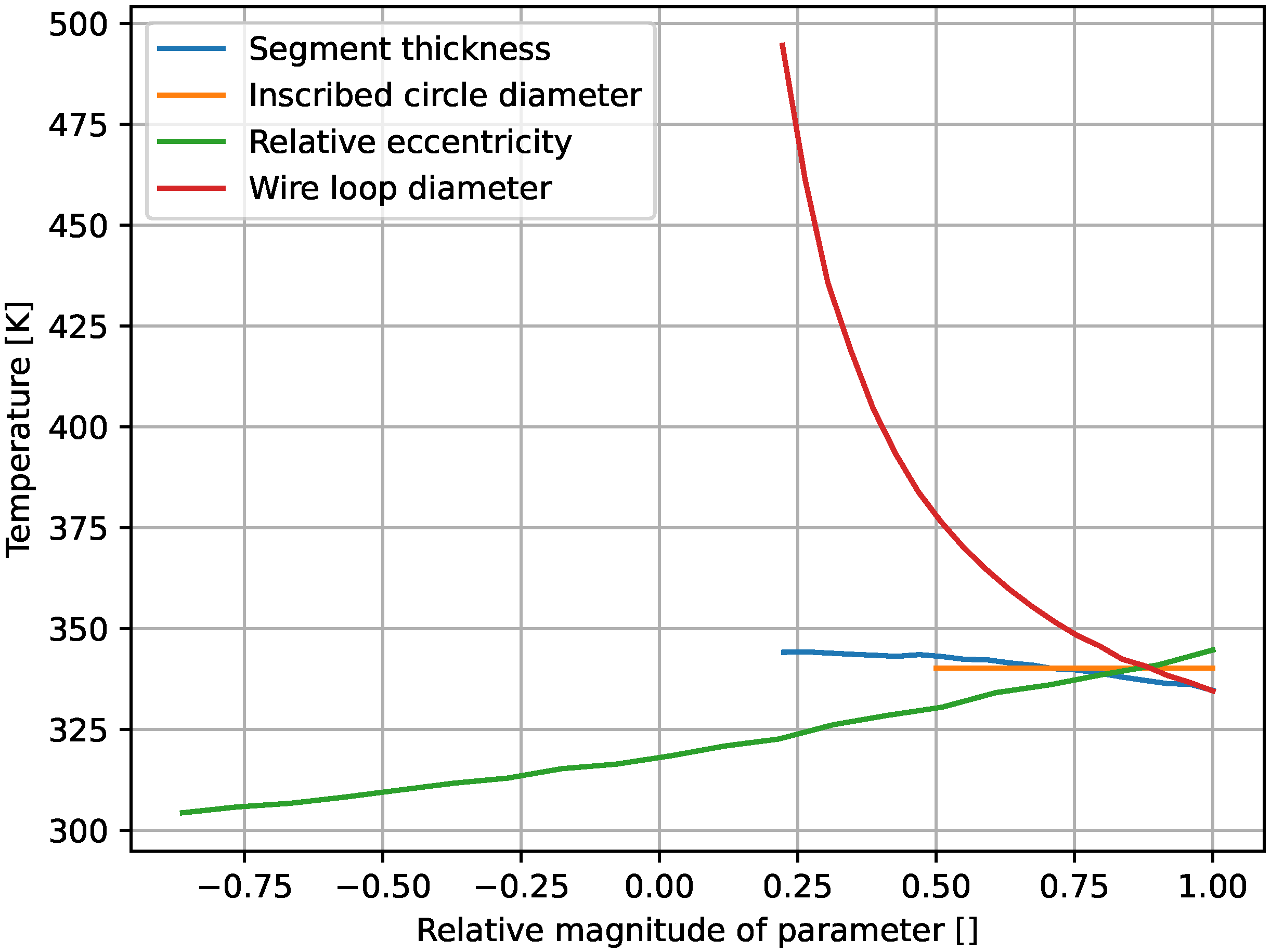
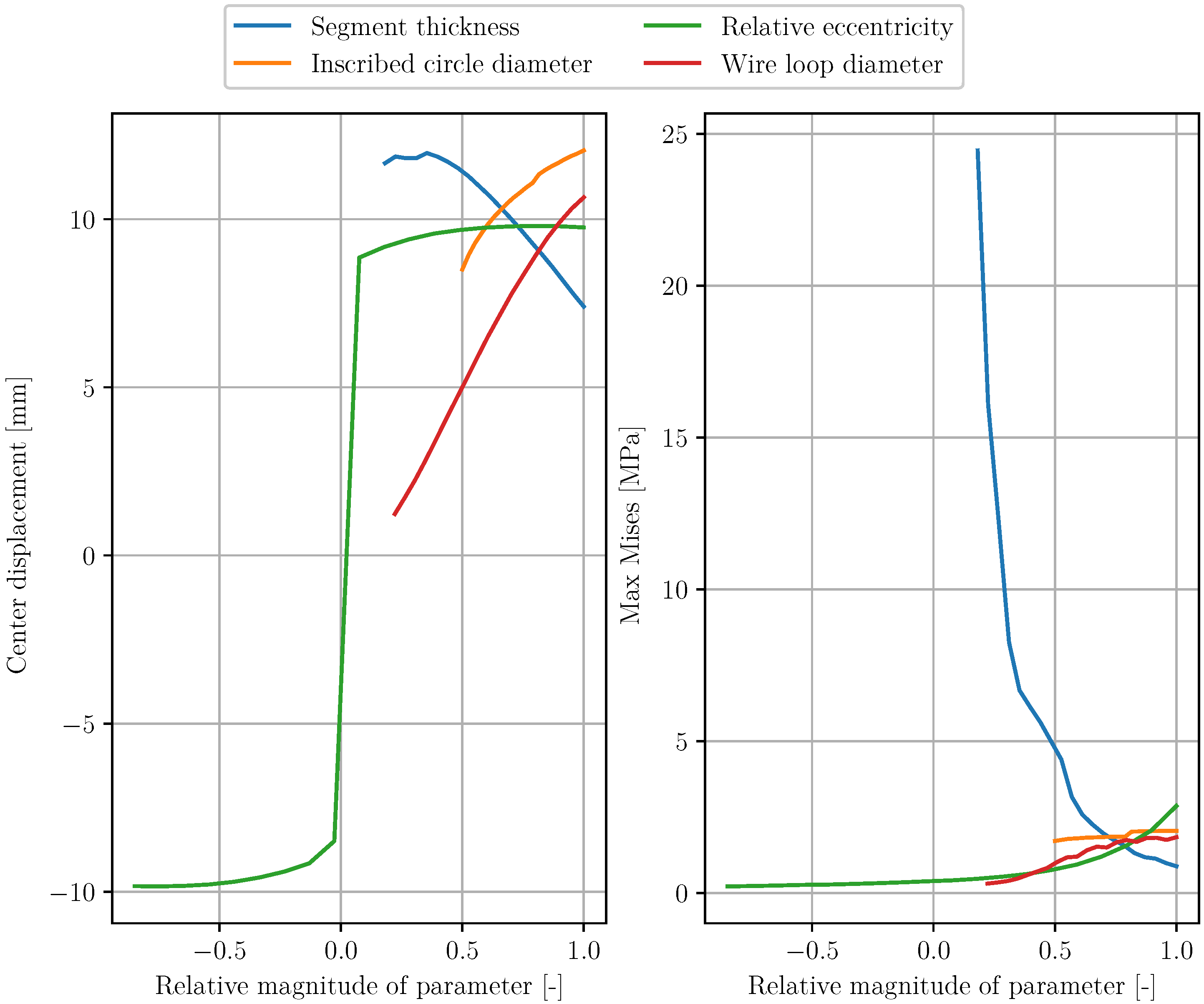
3.2. Parameter Study
4. Discussion
Author Contributions
Funding
Institutional Review Board Statement
Informed Consent Statement
Data Availability Statement
Conflicts of Interest
Abbreviations
| bwd | backward |
| fwd | forward |
| FE | finite element |
| FEA | finite element analysis |
| FEM | finite element method |
| SMA | shape memory alloy |
| SME | shape memory effect |
| T | temperature |
| TWSME | two-way shape memory effect |
| coefficient of thermal expansion of the backward transformation | |
| coefficient of thermal expansion of the forward transformation | |
| coefficient of thermal expansion | |
| c | spring constant |
| material parameter for elastomer | |
| specific heat capacity | |
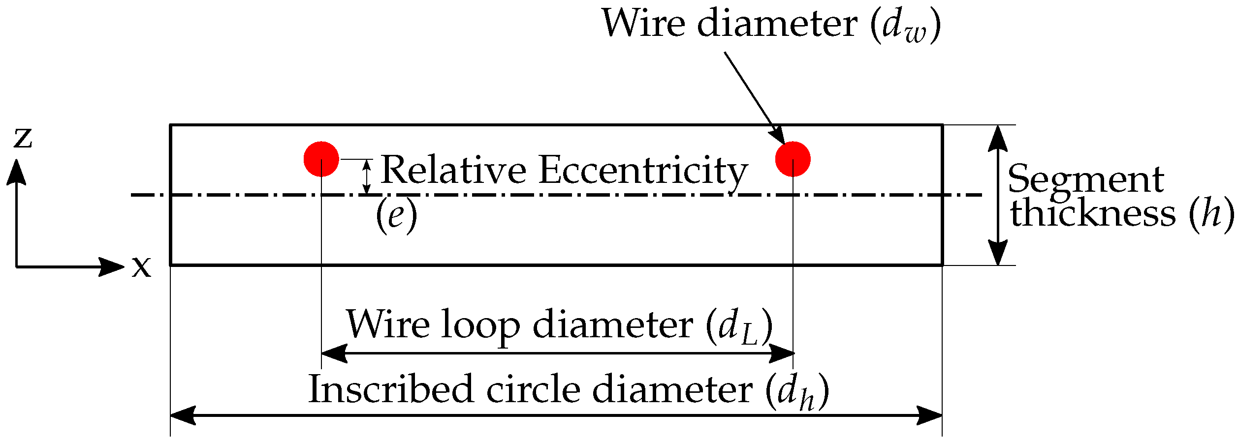
| inscribed circle diameter | |
| wire loop diameter | |
| wire diameter | |
| e | relative eccentricity |
| strain | |
| inelastic strain | |
| maximum strain | |
| E | elastic modulus |
| elastic modulus (austenite) | |
| G | shear modulus |
| h | segment thickness |
| invariants of the right Cauchy–Green tensor | |
| k | thermal conductivity |
| K | constant for demonstrate of hysteresis behavior |
| stretching in directions 1, 2 and 3 | |
| Poisson’s ratio | |
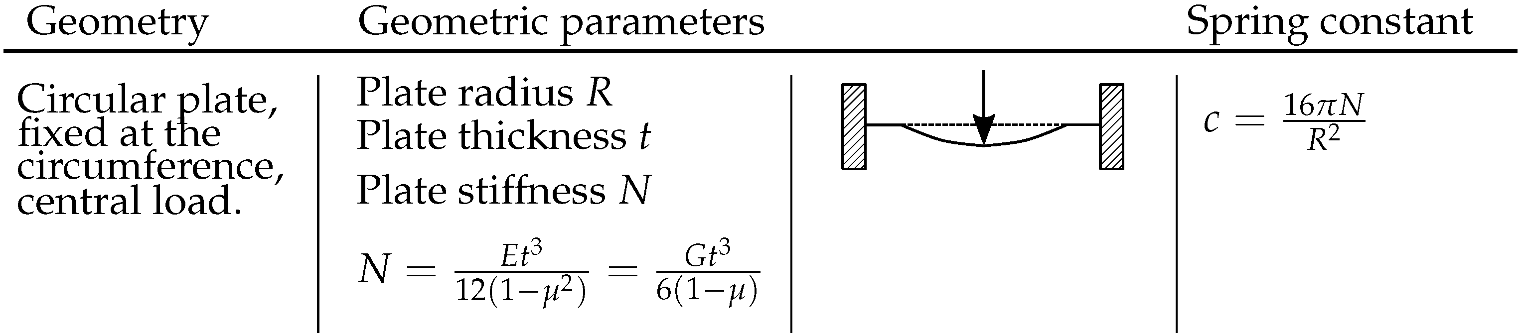
| N | plate bending stiffness |
| R | plate radius |
| density | |
| t | plate thickness |
| martensite fraction |
Appendix A
Appendix A.1. Figures Relating to Geometric Specifications


Appendix A.2. Geometry and Material Properties of Matrix and SMA Wire

| Parameter | Geometry | Matrix 1 | Wire |
|---|---|---|---|
| Segment thickness (h) | 8 | ||
| Relative eccentricity (e) | 50% | ||
| Wire loop diameter () | 80 | ||
| Wire diameter () | 375 | ||
| Inscribed circle diameter () | 120 | ||
| 1/12 Segment angle | 30 | ||
| 0 | |||
| 0 | |||
| Thermal conductivity (k) | |||
| Specific heat capacity () | 1400 | ||
| Density () | 500 | ||
| Thermal expansion coefficient () | |||
| 70 | |||
| Poisson’s ratio | 0.33 | ||
| Thermal conductivity (k) | 21 | ||
| Specific heat capacity () | 320 | ||
| Density () | 6690 | ||
Appendix A.3. Circular Plate Geometric Properties
Appendix A.4. Simulation Data
| Parameter | Value |
|---|---|
| Ambient temperature | |
| Film coefficient convection | |
| Time period actuation | 402 |
| actuation | 0 |
| actuation | 200 |
| actuation | 402 |
| Initial increment actuation | |
| Min. increment actuation | |
| Max. increment actuation | |
| Max. number of increments | |
| Current | |
| Voltage |
References
- Sinapius, J.M. Adaptronics-Smart Structures and Materials; Springer: Berlin, Germany, 2021. [Google Scholar]
- Lagoudas, D.C. Shape Memory Alloys: Modeling and Engineering Applications; Springer Science & Business Media: New York, NY, USA, 2008. [Google Scholar]
- Lecce, L.; Concilio, A. Shape Memory Alloy Engineering: For Aerospace, Structural and Biomedical Applications; Elsevier: Oxford, UK, 2014. [Google Scholar]
- Mabe, J.; Calkins, F.; Butler, G. Boeing’s variable geometry chevron, morphing aerostructure for jet noise reduction. In Proceedings of the 47th AIAA/ASME/ASCE/AHS/ASC Structures, Structural Dynamics, and Materials Conference, Newport, RI, USA, 1–4 May 2006; p. 2142. [Google Scholar]
- Savi, M.A.; Paiva, A.; Pacheco, P.M. Phenomenological modeling of shape memory alloy thermomechanical behavior. In Proceedings of the International Symposium on Solid Mechanics, São Paulo, Brazil, 3–7 January 2007; pp. 497–511. [Google Scholar]
- Paiva, A.; Savi, M.A. An overview of constitutive models for shape memory alloys. Math. Probl. Eng. 2006, 2006, 56876. [Google Scholar] [CrossRef]
- Patoor, E.; Lagoudas, D.C.; Popov, P.; Entchev, P.B.; Brinson, L.C.; Gao, X. Shape memory alloys, Part I: General properties and modeling of single crystals. Mech. Mater. 2006, 38, 391–429. [Google Scholar] [CrossRef]
- Lagoudas, D.C.; Entchev, P.B.; Popov, P.; Patoor, E.; Brinson, L.C.; Gao, X. Shape memory alloys, Part II: Modeling of polycrystals. Mech. Mater. 2006, 38, 430–462. [Google Scholar] [CrossRef]
- Lagoudas, D.C.; Entchev, P.B.; Popov, P.; Patoor, E.; Brinson, L.C.; Gao, X. Models for shape memory alloy behavior: An overview of modeling approaches. Int. J. Solids Struct. 2009, 1, 111–148. [Google Scholar]
- Tanaka, K. A thermomechanical sketch of shape memory effect: One-dimensional tensile behavior. Res. Mech. 1986, 18, 251–263. [Google Scholar]
- Liang, C.; Rogers, C.A. One-dimensional thermomechanical constitutive relations for shape memory materials. J. Intell. Mater. Syst. Struct. 1990, 1, 207–234. [Google Scholar] [CrossRef]
- Brinson, L.C.A. One-dimensional constitutive behavior of shape memory alloys: Thermomechanical derivation with non-constant material functions and redefined martensite internal variable. J. Intell. Mater. Syst. Struct. 1993, 4, 229–242. [Google Scholar] [CrossRef]
- Takagi, T.; Luo, Y.; Suzuki, S.; Matsumoto, M.; Tani, J. Modeling and numerical simulation on thermomechanical behavior of SMA plates with two-way shape memory effect. J. Intell. Mater. Syst. Struct. 2001, 12, 721–728. [Google Scholar] [CrossRef]
- Goraj, Z. An overview of the deicing and anti-icing technologies with prospects for the future. In Proceedings of the 24th International Congress of the Aeronautical Sciences, Yokohama, Japan, 29 August–3 September 2004. [Google Scholar]
- Gerardi, J.; Ingram, R.; Catarella, R. A shape memory alloy based de-icing system for aircraft. In Proceedings of the 33rd Aerospace Sciences Meeting and Exhibit, Reno, NV, USA, 9–12 January 1995. [Google Scholar]
- Myose, R.Y.; Horn, W.J.; Hwang, Y.; Herrero, J.; Huynh, C.; Boudraa, T. Application of Shape Memory Alloys for Leading Edge Deicing; SAE International: Warrendale, PL, USA, 1999. [Google Scholar]
- Sullivan, D.B.; Righi, F.; Hartl, D.J.; Rogers, J. Shape Memory Alloy Rotor Blade Deicing. In Proceedings of the 54th AIAA/ASME/ASCE/AHS/ASC Structures, Structural Dynamics, and Materials Conference, Boston, MA, USA, 8–11 April 2013; p. 1915. [Google Scholar]
- Liu, X.; Xing, Y.; Zhao, L. Study of shape memory alloy de-icing device for nonrotating components of aircrafts. In Proceedings of the IOP Conference Series: Materials Science and Engineering, Xishuangbanna, Yunnan, China, 16–17 June 2018; p. 032106. [Google Scholar]
- Tamer, O.; Kyriazis, A.; Sinapius, M. Parameter study and experimental analysis of a thermo-mechanical de-icing concept. Smart Mater. Struct. 2020, 29, 045021. [Google Scholar] [CrossRef]
- Kyriazis, A. Parameterstudie und Experimentelle Überprüfung eines Integrierten Thermo-Mechanischen Enteisungssystems. Master’s Thesis, Technical University of Braunschweig, Braunschweig, Germany, 2018. [Google Scholar]
- Xu, L.; Solomou, A.; Baxevanis, T.; Lagoudas, D.C. Finite strain constitutive modeling for shape memory alloys considering transformation-induced plasticity and two-way shape memory effect. Int. J. Solids Struct. 2021, 221, 42–59. [Google Scholar] [CrossRef] [Green Version]
- Den Hartog, J.P. Mechanische Schwingungen; Springer: Berlin/Heidelberg, Germany, 2013. [Google Scholar]


| Parameter | Min. Value | Max. Value (100%) |
|---|---|---|
| Segment thickness (h) | 11 | |
| Relative eccentricity (e) | ||
| Wire loop diameter () | 20 | 90 |
| Inscribed circle diameter () | 100 | 200 |
Publisher’s Note: MDPI stays neutral with regard to jurisdictional claims in published maps and institutional affiliations. |
© 2022 by the authors. Licensee MDPI, Basel, Switzerland. This article is an open access article distributed under the terms and conditions of the Creative Commons Attribution (CC BY) license (https://creativecommons.org/licenses/by/4.0/).
Share and Cite
Tamer, O.; Walter, F.; Sinapius, M.; Böl, M. A Computational Geometric Parameter Optimization of the Thermomechanical Deicing Concept. Actuators 2022, 11, 223. https://doi.org/10.3390/act11080223
Tamer O, Walter F, Sinapius M, Böl M. A Computational Geometric Parameter Optimization of the Thermomechanical Deicing Concept. Actuators. 2022; 11(8):223. https://doi.org/10.3390/act11080223
Chicago/Turabian StyleTamer, Ozan, Fabian Walter, Michael Sinapius, and Markus Böl. 2022. "A Computational Geometric Parameter Optimization of the Thermomechanical Deicing Concept" Actuators 11, no. 8: 223. https://doi.org/10.3390/act11080223
APA StyleTamer, O., Walter, F., Sinapius, M., & Böl, M. (2022). A Computational Geometric Parameter Optimization of the Thermomechanical Deicing Concept. Actuators, 11(8), 223. https://doi.org/10.3390/act11080223