Abstract
The bionic design of muscles is a research hotspot at present. Many researchers have designed bionic elastic actuators based on the Hill muscle model, and most of them include an active contraction element, passive contraction element and series elastic element, but they need more parametric design of mechanical structure and control under the guidance of Hill muscle model. In this research, a nonlinear series elastic cable actuating mechanism is designed in which the parameters of the elastic mechanism are optimized based on the Hill muscle model to fit the nonlinear passive elasticity of a muscle. Through the force–position relationship determined by the Hill muscle model, the output force and position of a nonlinear series elastic cable actuator are controlled to simulate the active contraction performance of a muscle. The experiments show that the proposed design and control method can make the nonlinear cable actuator have good muscle-like output force–displacement characteristics.
1. Introduction
In recent years, various wearable exoskeleton and rehabilitation robots have developed rapidly. To meet the requirements of safe human–robot physical interaction and wearability, robot actuators need to have the characteristics of compliant driving and high-power weight ratios [1]. Skeletal muscle is one of the most important tissues in the human body. It can produce enough force to drive joint movement smoothly and efficiently. At present, most robot-actuating mechanisms are rigid, and there is still a big gap compared with the performance of skeletal muscle, so bionic skeletal muscle design is a research hotspot at present [2]. Researchers mainly use two engineering methods to achieve the bionic design of muscles: One method is to design artificial muscle using various new driving principles [3]. Additionally, traditional motor and hydraulic driving parts are used to design various adaptive elastic actuators to simulate the function of a musculoskeletal system so that robot joints show the characteristics of flexibility, safety, and high energy efficiency in the movement process [4].
The new driving principles of artificial muscle mainly include fluid pressure actuating, thermal deformation actuating, and electric deformation actuating. Compared with other driving methods, fluid pressure actuating artificial muscle is mature and has obvious advantages in terms of power density, load capacity, flexibility, and service life, but it also has some disadvantages, such as the need to provide pressure source, instability in rapid response, and obvious hysteresis [5]. Among them, hydraulic actuators and pneumatic actuators belong to fluid pressure actuators. A hydraulic actuator has a large actuating force, but it is heavy, and its nonlinear characteristics such as hysteresis, creep, thermal drift will also affect the overall performance [6]. A pneumatic artificial muscle actuator has greater contraction and activation force, and it is lighter than hydraulic components, but the nonlinear relationship between its acting force and driving pressure is complex and difficult to control [7]. A thermal deformation-driven artificial muscle mainly includes the phase change type and the fiber type. It can produce a large driving force and has a small volume, but it also has a slow response rate, low energy conversion efficiency, and obvious hysteresis [8,9]. Electric deformation actuators mainly include dielectric elastomer actuators (DEAs) [10] and ion-exchange polymer–metal composites (IPMCs) [11]. A DEA has high power density, stress, strain, response speed, and energy efficiency. However, the driving voltage is high (10–100 V)/μm), and the hysteresis is obvious [12]. Although the driving voltage of an IPMC is low, the power density and the electric stress are small [13]. At present, the artificial muscles with new driving principles have their own advantages, but they are still immature, and there is a gap in the comprehensive performance level of biological muscles. An elastic actuator driven by a motor or hydraulic pressure is more mature and reliable than the artificial muscle with new driving principles. The Hill muscle model can describe muscle contraction well. The model is usually composed of three units: a contraction element (CE), a series elastic element (SE), and a parallel elastic element (PE) [14]. SEs and PEs regulate the passive elasticity of muscle stiffness and energy storage, which is of great significance to the efficiency and safety of joint movement. A CE is the core element of the Hill muscle model, and it can produce active muscle contraction [15]. According to the structural similarity of the Hill muscle model, researchers have designed various elastic actuators, which are mainly divided into series elastic actuators (SEAs) [16], parallel elastic actuators (PEAs) [17], clutchable elastic actuators (CEAs), and multi-configuration elastic actuator (MEAs) [18,19]. In terms of the transmission mode, elastic actuators can be divided into rotary types and linear types. The Bowden cable-driven mechanism is often used in linear elastic actuators. This mechanism can transfer force and displacement from the proximal end to the distal end and propagate for a long distance in a narrow bending space. The transmission path can be changed into a specific shape according to the space requirements. Therefore, it has been widely used in some wearable exoskeletons and rehabilitation robots [20].
At present, elastic actuators often simulate the series elasticity, parallel elasticity, and active contraction elements of muscle in terms of the structural composition [21]. If a cable-driven elastic actuator can be parametrically designed and controlled under the guidance of the Hill muscle model to simulate the active and passive output characteristics of skeletal muscle, it will undoubtedly make the actuator more in line with the characteristics of biological muscle. Some researchers have carried out similar research work. D. F. B. Haeufle designed a series elastic actuator. The actuator used a linear spring to simulate the passive characteristics of a muscle. The motor was controlled based on the Hill muscle model to achieve the muscle-like force velocity output characteristics of the actuator, and a rapid release experiment was carried out [22]. However, compared with muscle, the passive elastic stiffness of the driver was a fixed value. Shen developed a type of artificial muscle actuated by a motor and tendon-sheath system based on the Hill muscle model [23], and Shao also designed artificial muscles to express the transmission characteristics of skeletal muscle [24]. However, the series elastic element in these actuators are treated as linear elasticity, which is inconsistent with the characteristics of the real skeletal muscle. He also proposed the force deformation transfer model and control method of a flexible cable actuator, which were verified by simulation and experiments [15]. The actuator adopted the combination of series and parallel springs to achieve the nonlinear passive stiffness of skeletal muscle, which could completely simulate the output characteristics of muscle, but the overall structure was slightly complex. Gialias and Matsuoka used nonlinear elastic composites to simulate the passive nonlinear elasticity of skeletal muscle, and they used a cable driven by a motor to simulate the active contraction force [25]. The passive elastic composite was connected in parallel with the motor drive cable to achieve the complete simulation of skeletal muscle output force–displacement characteristics, but the elastic composite in the actuator needed to be customized to fit the nonlinear passive stiffness of different skeletal muscles. Richter and Asano used a cable-driven nonlinear elastic actuator to simulate human muscle in the design of a humanoid musculoskeletal robot [26,27], but they did a smaller study on the method of parametric design and control of the actuator based on the Hill muscle model.
It can be seen from the above research status that many researchers have designed bionic elastic actuators based on the Hill muscle model, and most of them include active a contraction element, passive contraction element and series elastic element, but they need a more parametric design of mechanical structure and control under the guidance of the Hill muscle model. In this research, the passive elastic mechanism of an actuator is parameterized and designed based on the Hill muscle model to fit the nonlinear passive elasticity of a muscle. Based on the force–position relationship determined by the Hill muscle model, the sensorless force control method is used to control the NSECA and to achieve the muscle-like active force–position characteristics. Compared with previous studies, the muscle-like actuator discussed in this research is simple in composition and easy to manufacture and control, and it can simulate the nonlinear passive elasticity and active contraction force of skeletal muscle well. The rest of this paper is organized as follows: The second section introduces the Hill muscle model briefly. In the third section, the composition and basic principle of the NSECA in this research are introduced, and the main mechanical parameters are optimized based on the Hill muscle model. In the fourth section, the theoretical model of the actuator is established and the force position control method according to the Hill muscle model is introduced. The fifth section describes how the experimental research is carried out. The sixth section gives the conclusion of this paper.
2. Muscle Model
Figure 1 shows the improved Hill muscle model [28]. The Hill muscle model consists of a series elastic element (SEE), passive elastic element (PEE), contraction element (CE), viscous damping element (VE), and pinnate angle . In Figure 1, lmt is the muscle length, lm is the muscle fiber length, and lt1 and lt2 are the tendon lengths at both ends.
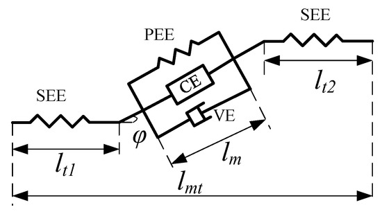
Figure 1.
Hill muscle model.
The relationships of the muscle length, muscle fiber length, and tendon length are as follows:
The formula of the muscle force is as follows:
In Equation (2), FCE, FPE, and FVE are the active forces of the muscle fibers, the passive forces of the muscle fibers, and the viscous damping forces.
The size of FCE is determined by the muscle activation, muscle fiber length, muscle fiber contraction speed, and maximum muscle force. The formula for FCE is as follows:
In Equation (3), , fl, fv, and F0 are the muscle activation degree, the influence factor of the muscle fiber length, the influence factor of the muscle fiber contraction speed, and the maximum isometric contraction force at rest, respectively.
In Equation (3), the muscle activation is calculated with the following formula:
In Equation (4), u(t) and A are the normalized EMG signal and the nonlinearity degree.
The influence factor fl of the muscle fiber length and the influence factor fv of the muscle fiber contraction speed in Equation (3) are calculated with the method of Thelen [12].
In Equation (5), lm and lmopt are the real-time muscle fiber length and the resting muscle fiber length. γ is the shape coefficient, which is 0.5 for older people and 0.45 for younger people.
The calculation formula of fv in Equation (3) is as follows:
In Equation (6), vn is the normalized contraction velocity. As is the curve parameter, and its value is 0.25. fM is the maximum force of muscle fiber elongation (the normalization of the muscle fiber active force), which is 1.4 for younger people and 1.8 for older people.
The calculation of FPE can be obtained by multiplying fPE and F0.
fPE can be calculated using the length of the muscle fiber. When the length of the muscle fiber is less than or equal to the rest length, no passive force is generated. When the length of the muscle fiber is greater than the rest length, passive force is generated. We also use the formula of Thelen for calculation [12]. The formula is as follows:
In Equation (8), kPE is the curve shape parameter, and its value is 4. is the maximum passive strain.
The addition of the viscous damping force FVE helps to simulate the ability of a muscle to eliminate high-frequency oscillation. However, the damping force of a muscle at low speed is very small, so viscous damping force is ignored in this research. Letting the normalized muscle contraction velocity vn be −0.01, the minus sign represents contraction. The maximum muscle force is normalized, and then, according to Equations (1)–(8), the schematic diagram of the muscle force composition (muscle activation degree is 1), as shown in Figure 2, can be obtained. The parameters in the Hill muscle model are obtained according to the research by Thelen and Holzbaur [17,29].
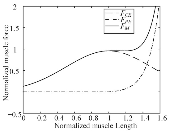
Figure 2.
Schematic diagram of muscle force composition.
3. Mechanism of the Actuator
3.1. Mechanism Design
It can be seen from Figure 2 that in order to simulate the output characteristics of a muscle, it is mainly necessary to simulate the active contraction force and passive elastic properties of a muscle. To reduce the complexity of the muscle-like actuator’s mechanical structure, because the motor is more mature, reliable, and can provide more accurate control, in this research, a motor and a nonlinear series elastic element are used to design a muscle-like flexible cable actuator. As shown in Figure 3, the motor is actively controlled according to the Hill muscle model. Nonlinear spring modules are connected in series at the motor output to provide passive variable stiffness characteristics like those of a muscle.
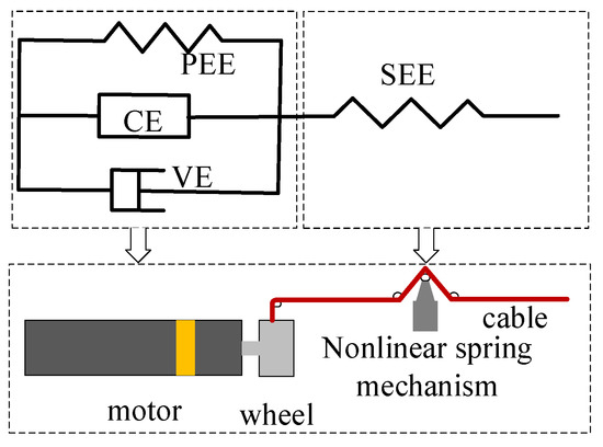
Figure 3.
Equivalent nonlinear series elastic mechanism of muscle.
As shown in Figure 4, the NSECA includes a motor, a planetary reducer, a winding wheel, a cable, a guide rod, a linear bearing, a linear compression spring, and three pulleys. The winding wheel is directly connected to the reducer output rotating shaft, and the motor’s rotation torque is transformed into the cable’s tension through the winding wheel shown in Figure 4b. The linear spring passes through the linear guide rod. One end of the linear guide rod passes through the linear bearing and connects with pulley 2, and they are all connected to a linear displacement sensor. The motor in the actuator is a CBL2453-2423f motor from the TECHSERVO Company (Shenzhen, China), and it is equipped with a gear reducer. The rated output torque of the motor is 27.28 Nm, and the reduction ratio of the reducer is 100. The KSF50 of Miran is selected as the linear displacement sensor, which is based on the principle of a potentiometer. Its stroke is 50 mm, and its linear accuracy reaches 0.1%. The cable in the existing cable driving mechanism generally adopts Bowden wire, Kevlar wire, and Dyneema wire. Bowden wire has low friction and high strength, but its bending capacity is poor, and its winding requires a large diameter. Dyneema wire is easy to break due to friction overheating. Kevlar wire has high strength, good wear, and fire resistance, and it is soft and easy to bend. In order to reduce the volume of the actuator, the diameters of the winding wheel and the pulley are 6 mm. Considered comprehensively, Kevlar wire with a good bending capacity is adopted in this research.
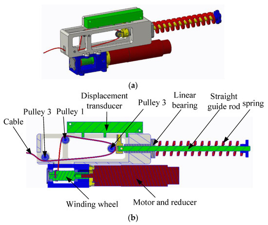
Figure 4.
Schematic diagram of NSECA. (a) Appearance drawing. (b) Profile of the actuator.
3.2. Nonlinear Elastic Analysis
The force analysis of the cable actuator is shown in Figure 5. We let the centers of the three pulleys be points Ac, Bc, and Cc, and the friction is ignored. It is assumed that the cable tension at the pulleys Ac and Cc is Fc, and the spring force at the pulley Cc is Fe. We define the direction of spring compression as the vertical direction. We let the initial vertical distance between AcBc be b, the vertical distance between AcCc be c, the horizontal distance between AcBc and the horizontal distance between AcCc be a, and the angle between the connecting line of BcCc and the vertical line be a α. The angle between the AcBc line and the vertical line is β. After spring compression, the real-time vertical distance between the AcBc points is ξ, and the value range of ξ is [0, b]. The elastic coefficient of the spring is k.
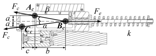
Figure 5.
Force analysis of cable actuator.
According to the force analysis of the cable actuator in Figure 4, the cable tension Fc can be deduced as follows:
In Equation (9), α and β can be obtained using the geometric relationship.
The spring force Fe satisfies the following formula:
Combining Equations (9)–(12), the tension Fc on the cable can be obtained as follows:
We let the change of the cable length caused by the spring deformation be Δl. From the geometric relationship, Δl satisfies the following formula:
If the equivalent stiffness of the cable actuator is Km, then:
The equivalent passive stiffness of the NSECA is:
According to Equations (13)–(16), the equivalent stiffness of the rope driver in this research can be obtained. The equivalent stiffness is related to the four parameters k, a, b, and c.
3.3. Mechanism Parameter Optimization for Passive Elastic Imitation
Taking the long head of the biceps brachii of a human’s upper limb as an example, according to the Hill muscle model described in Section 2, the muscle output force–displacement relationship of the long head of biceps brachii can be obtained. By optimizing the four parameters k, a, b, and c in the actuator, the actuator can have the passive elastic property of the long head of the biceps brachii. Among the four parameters, parameter c is used to maintain the pulley spacing, which can be taken as a fixed value. Considering the size of the whole mechanism, the parameter takes the value of 0.01 m. For parameter b, take a value slightly larger than a half of the length variation as the initial estimate, which is 0.02 m based on the anatomical data of the long head of the biceps. The minimum value of parameter a is 0.01 m, which is used to maintain the pulley spacing. The initial value of k is 3750N/m. The initial value of k is calculated according to the maximum output force of the actuator and the initial values of a, b, and c. when the maximum output force Fc of the actuator designed in the experiment is 50 N, and the geometric parameters a, b and c are 0.01 m, 0.02 m and 0.01 m, the value range of ξ is [0, b]. According to Equation (13), the initial stiffness k of the linear spring is 3750 N/m. We add a description of how to calculate the initial value of k. After selecting the initial value, the three parameters are divided into three levels, and the test object is three factors and three levels, as shown in Table 1. The optimal combination of parameters is quickly selected with an orthogonal test. The L9 (34) scale is used to select the combination of test objects, and nine groups of test parameters combinations are obtained. Then, nine groups of data are simulated and compared to obtain the optimal scheme.

Table 1.
Selection of test parameters.
Figure 6 shows the simulation results of the test combination. When the seventh group of parameters is taken, the passive force–displacement curve of the actuator obtained by simulation is closer to the muscle’s passive force–displacement curve obtained with the Hill muscle model. At this point, k, a, b, and c are 4250 N/m, 0.025 m, 0.025 m, and 0.01 m, respectively.
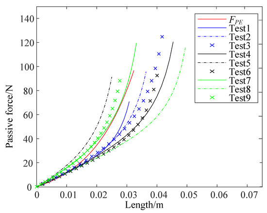
Figure 6.
Simulation results of passive force–displacement relationship obtained by nine groups of parameters.
4. Active Contraction Force Control
4.1. Modeling of the Actuator
In order to control the active contraction force, as described in this section, the theoretical model of the cable actuator is established first, and then the force control method is introduced. The motor in the cable actuator is described with the following equation:
where τm is the torque output of the motor, kgear is the reduction ratio of the planetary reducer, r is the radius of the winding wheel, Jm is the inertia moment of the motor, JW is the inertia moment of the winding wheel, and θm is the angular displacement of the motor. If the total displacement of the cable actuator is Δlmt (which includes the cable displacement caused by the deformation of the elastic element and the displacement caused by the active rotation of the motor), the angular displacement θm of the motor is:
In Equation (18), Δl(ξ) represents the cable length change caused by nonlinear spring deformation, which can be obtained according to the geometric relationship of the mechanism, and which satisfies Equation (14). Equation (13) deduces the relationship between the cable force Fc and ξ when the friction is neglected.
However, in the working process of the cable actuator, friction will inevitably occur between the cable and pulley, as well as between the cable and the sheath. In this research, only the friction between the cable and pulley is considered, and the friction between the cable and the cable sheath is not considered. The influencing factors of the friction force between the cable and the pulley include the roller material, the angle of the cable wrapping rotating mechanism, and the load on the cable. Relevant references have analyzed and modeled the influencing factors of this kind of cable driving mechanism [30]. Studies have shown that the cable angle has little effect on the friction force. Additionally, the pulley in this research is a rolling pulley with bearings. Therefore, the friction between the cable and the pulley mainly comes from the load on the cable.
We let the load-related friction coefficient be k1.
In Equation (19), Fc1 is the cable end tension after compensation.
According to the existing research [30], the model of the load and friction coefficient is in accord with the exponential function characteristics, as shown in Equation (20).
In Equation (20), u, v, and w are shape parameters that have no practical significance and can be fitted after the data are obtained from experiments.
According to Equations (13), (19), and (20), the end tension Fc1 of the cable actuator after friction compensation is:
The armature voltage and the output torque of the motor in the actuator satisfy the following formula:
In Equations (22) and (23), ua represents the armature voltage of the motor, ra represents the interphase resistance, i represents the loop current, La represents the interphase inductance, kb represents the back electromotive force constant, and kt represents the torque constant of the motor.
4.2. Force Control Method of the Actuator
In order to achieve force control, the traditional mechanism needs to be equipped with force sensors. In this research, the cable tension is indirectly obtained by measuring the spring deformation in the series elastic mechanism. At present, the common SEA controller includes an inner loop and an outer loop. The outer loop is a force control loop that obtains the force control command according to the force reference value and the displacement feedback of the elastic element. The inner loop is a position loop that obtains the motor position control command according to the force control command. This method is also adopted in this research [31]. Figure 7a shows a block diagram of the tension control system of the cable actuator in this research. For a given force reference value Fc1ref, according to the Hill muscle model, the displacement reference value Δlmtref corresponding to Fc1ref can be obtained. In the working process of the actuator, ξ can be obtained with the linear displacement sensor in the actuator, so the tension feedback Fcla can be obtained with Equation (21). After passing through the PID controller, the passive displacement Δlref of the cable actuator caused by the tension on the cable can be solved. Since the total displacement at the end of the cable actuator is Δlmtref, the displacement of the cable caused by the active rotation of the motor can be obtained and output to the motor for position closed-loop control. Figure 7b shows the motor control block diagram, which adopts double closed-loop control combining the position loop and the current loop.
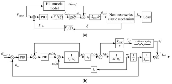
Figure 7.
Block diagram of rope driver control system. (a) System control block diagram. (b) Motor closed-loop control block diagram.
5. Experiments
Firstly, the output force–displacement performance test platform of a rope driver is built. Then, the passive elastic characteristics and active contraction force–position control performance of the cable actuator are verified by experiments.
5.1. Experiments Platform
As shown in Figure 8, the experimental platform built in this research mainly includes a controller, motor driver, base plate, cable actuator, tension sensor, and load. The cable actuator is affixed to the flat base, the cable output end is affixed to the tension sensor, and the other end of the tension sensor is affixed to the load. In the passive elastic performance experiment, different tensile forces are applied at the end of the cable actuator, the data for the linear displacement sensor are recorded, and the relationship between the tension and the passive displacement is obtained. In the active contraction control experiment, the force command is given first, and then the cable displacement command is determined according to the Hill muscle model. In the experiment, the embedded single-chip microcomputer is used as the controller. The motor position control command is obtained by using the control method introduced in Section 4, and the motor driver is used to control the motor rotation. The BSLS-1 model from the BUFSON company is selected as the tension sensor, and its measuring range is ±20 kg a precision of 0.03 %. The tension sensor used in this research is only used to measure the cable tension in the path and does not participate in the actual control process. The linear displacement sensor in the actuator selects the KSF50 model of MIRAN, whose stroke is 50 mm, and the linear accuracy is 0.1%.
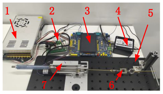
Figure 8.
Schematic diagram of experimental platform (1—power supply, 2—motor driver, 3—controller, 4—signal converter, 5—base plate, 6—tension sensor, 7—cable actuator).
5.2. Force Control Experiments of the Actuator
In order to achieve the simulation of active contraction force–position relationship based on the Hill muscle model, firstly, the tension on the cable actuator needs to be reliably controlled. The end of the cable is fixed. Given the tension command, the tension on the cable actuator is controlled according to the method described in Section 4.2. Without the addition of friction compensation, the tension sensor data in the test-bed is recorded, and the relationship between the tension command and the actual tension is shown in Figure 9. The tension data in the red dotted line in Figure 9 indicate the average tension obtained after 10 measurements, and the maximum and minimum values are excluded. It can be seen from the figure that the tension command differs greatly from the actual value, the maximum error reaches 4.4629 N, and the corresponding error ratio reaches 17.19%.
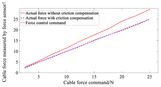
Figure 9.
Comparison of NSECA control effect based on friction compensation.
According to the experimental data shown in Figure 9, it is assumed that the model of the rope tension and the friction coefficient conforms to the characteristics of the exponential function (Equations (19) and (20)). It can be determined that u is −0.4077, v is −0.603, and w is 0.247. Figure 10 shows the fitting curve of the friction coefficient for different cable tensions. The fitting coefficient is substituted into Equations (20) and (21) is used to calculate the cable tension with friction compensation, as shown in the purple dotted line in Figure 9. At this time, the tension command is very close to the value observed by the tension sensor, and the tension error after compensation is within 0.5 N.
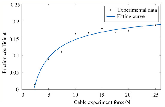
Figure 10.
Friction coefficient of NSECA under different rope tensions.
After friction compensation, the force step response and the dynamic force following experiment for the cable actuator are carried out. In order to cause the cable to be under tension, an initial tension force of 0.6 N is applied to the cable. As shown in Figure 11, the step force response result of the cable actuator is shown. The actuator receives a 20 N tension command in 0.17 s, reaches 20 N in 0.82 s, and then remains stable. The adjustment time of the step response is about 0.7 s, and the overshoot is 0.166 N. The above experiments show that the tension control and the friction compensation method described in Section 4.2 are effective, and they can control the tension on the cable actuator accurately.
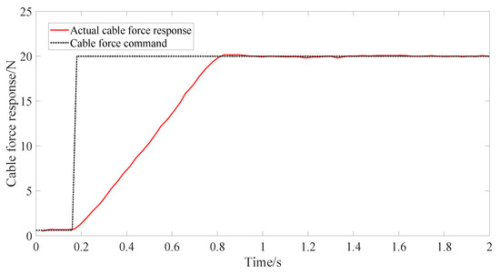
Figure 11.
Step force response of cable actuator.
Figure 12a shows the experimental result of the sine force following the nonlinear cable SEA, in which the amplitude of the input force command is 22 N and the period is 4 s. Figure 12b shows the tracking error of the sinusoidal force command, in which the initial error is the process when the cable actuator is loaded to the preset tension of 2.5 N. Then, the error changes nearly periodically, and the peak value is within 1.5 N. It can be seen from Figure 12 that there is a good dynamic force following effect for the period of 4 s. Due to the slow movement of an elderly wearer, this can meet the requirements of the exoskeleton for the force control bandwidth, and it can meet the requirements of the force control bandwidth of the assist exoskeleton. Because the inner loop of force tracking control is based on PID position control, the phase lag of Figure 12 is due to the time lag of position feedback control. Without changing the control method, this delay can only be reduced by adjusting the controller parameters or increasing the driving ability of the motor. The control effect can be improved by adding feedforward to make the controller phase synchronization or advance.
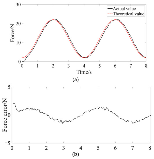
Figure 12.
The sinusoidal force command following experimental results. (a) Sinusoidal command tracking curve. (b) Sinusoidal command tracking error curve.
5.3. Passive Elastic Performance Verification
Figure 13 shows the results of the passive elastic performance test using the method described in Section 5.1. According to the results of the optimization design described in Section 3.3, the stiffness k of the linear spring in the cable actuator is 4250 N/m. The Geometric a, b, and c are 0.025 m, 0.025 m, and 0.01 m, respectively. In Figure 13, the red curve shows the passive force of the biceps brachii calculated according to the Hill muscle model theory. The black curve is the passive force–displacement theoretical curve of the nonlinear elastic mechanism optimized according to the Hill muscle model. The round points represent the experimental values. In the experiment, the resting length of the long head of the biceps brachii is 0.116 m. Therefore, when the length of the cable actuator is greater than 0.116 m, the cable begins to stretch and there is tension on the cable. When the length is less than 0.116 m, there is no tension on the cable. It can be seen from Figure 13 that the nonlinear spring mechanism optimized in this research can simulate the nonlinear elasticity of the long head of the biceps brachii well. However, compared with the theoretical force–displacement curve of the nonlinear spring mechanism, there are some differences, which are mainly caused by the friction compensation deviation, machining and assembly deviation, and measurement error. If the simulation of the nonlinear elasticity of different muscles is desired, the redesign of the main parameters of the nonlinear spring mechanism is necessary.
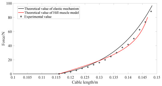
Figure 13.
Passive elastic characteristic experiment.
5.4. Contraction Force–Position Relationship Verification
According to Equation (3), the active contraction force is related to the activation degree of muscle. This paper does not actually collect the actual EMG signal of the long head of biceps brachii, but uses the open source biomechanical simulation software Opensim4 1 to obtain the EMG signal of the long head of biceps brachii in the specified motion state (in the isotonic state, the elbow moves from 0° to 90° and then returns to 0° within 4 s), and then the activation degree of biceps brachii after processing is obtained (as shown in Figure 14). By substituting this activation degree into the Hill muscle model of the long head of biceps brachii, the theoretical active contraction force (blue dotted line in Figure 15), passive contraction force (red dotted line in Figure 15) and resultant force (red solid line in Figure 15) of the long head of biceps brachii can be obtained. Take the active contraction force as the force control command and use the force control method introduced in the previous section to control the active contraction force. Use the experimental platform shown in Figure 8 to measure the resultant force at the end of the cable actuator and the change of the cable length, and the output force–displacement experimental curve of the nonlinear series elastic actuator is obtained, as shown by the diamond point in Figure 15.
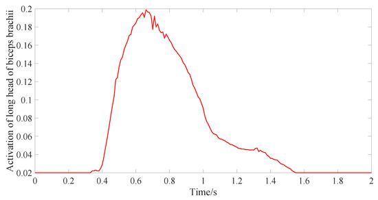
Figure 14.
Activation of the long head of the biceps brachii during flexion.
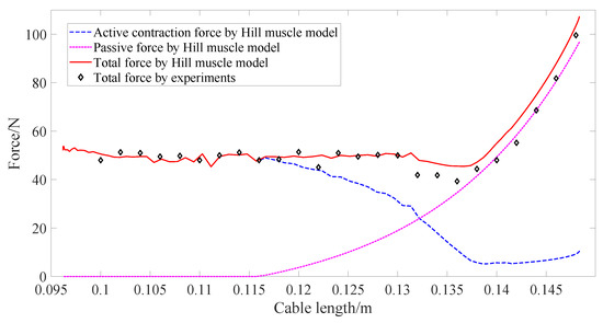
Figure 15.
Active contraction experimental verification.
As can be seen from Figure 15, the passive contraction force does not work when the cable length of the actuator is less than the resting length of long head of biceps brachii (about 0.116 m). Once the cable length of the actuator is stretched beyond the resting length under the action of the end load, the passive contraction force will gradually occupy most of the end force of the actuator, and the active contraction force will reduce gradually, which can protect muscle fibers from strong loading force. The bionic design and control method in this paper can simulate the output force displacement relationship of the long head of biceps brachii under isotonic contraction. Compared with the theoretical value obtained by the Hill muscle model, the root mean square error is 3.3483. The error of experimental data and theoretical data mainly comes from mechanism model error and friction. In terms of mechanical structure, the cable actuator designed in this paper does not simulate the parallel elastic (PEE) element included in the Hill muscle model, but uses the method of active control of motor to simulate the combined effect of active contraction element and parallel elastic element in the Hill muscle model. In addition, the output force velocity characteristics of muscle have not been studied in this paper.
6. Conclusions and Discussion
In this research, the design and control method of a type of nonlinear series elastic cable actuating mechanism with a muscle-like force–displacement relationship is studied. The nonlinear passive elasticity is simulated by a triangular spring assembly composed of a linear spring and a pulley block, in which the mechanism parameters are optimized based on the Hill muscle model. The simulation of the relationship between the active contraction force and the displacement is achieved with the active control of the motor. The experimental results show that the nonlinear series elastic actuator designed in this research can simulate the force–displacement output characteristics of muscle well. The actuator is suitable for robots, exoskeletons, and medical equipment that require flexible actuators and large output.
Compared with the existing research, the bionic actuating mechanism in this research adopts a simple pulley block and linear spring, which achieves the simulation of muscle nonlinear series elasticity and avoids the difficulty of obtaining elastic elements that meet the nonlinear elastic characteristics of muscle. By establishing an accurate mathematical model of the actuating mechanism, introducing friction compensation, and obtaining the tension and position command of the cable actuator based on the Hill muscle model, the imitation of muscle active contraction force and position control is achieved. The limitations of this research are that the mechanism parameters need to be changed when simulating different muscles, and the friction between the cable and the sheath of the cable actuator and the influence of the cable bending on the friction have not been compensated for in the model. In addition, the isometric contraction and the rapid release performance of the bionic cable actuator need to be studied in follow-up work.
Author Contributions
Conceptualization, Y.S.; methodology, B.H., H.L. and H.Z.; supervision, H.Y.; data curation, H.L.; writing—review and editing Y.S. and B.H. All authors have read and agreed to the published version of the manuscript.
Funding
This work was supported in part by National Key R&D Program of China (2020YFC2005800 & 2020YFC2005804) and in part by Natural Science Foundation of Shanghai China (20ZR1437800).
Institutional Review Board Statement
Not applicable.
Informed Consent Statement
Not applicable.
Data Availability Statement
Not applicable.
Acknowledgments
The authors would like to thank the National Key R&D Program of China (2020YFC2005800 & 2020YFC2005804) and the Natural Science Foundation of Shanghai China (20ZR1437800) for their support.
Conflicts of Interest
The authors declare that they have no conflict of interest.
Abbreviations and Symbols
| NSECA | nonlinear series elastic cable actuator |
| SEE | series elastic element |
| PEE | passive elastic element |
| CE | contraction element |
| VE | viscous damping element |
| PID | Proportion-Integration-Differentiation |
| pinnate angle | |
| lmt | muscle length |
| lm | muscle fiber length |
| lt1, lt2 | the tendon lengths at both ends |
| muscle force | |
| FCE | active forces of the muscle fibers |
| FPE | passive forces of the muscle fibers |
| FVE | viscous damping forces |
| muscle activation degree | |
| fl | influence factor of the muscle fiber length |
| fv | influence factor of the muscle fiber contraction speed |
| F0 | maximum isometric contraction force at rest |
| u(t) | normalized EMG signal |
| A | nonlinearity degree |
| lm | real-time muscle fiber length |
| lmopt | resting muscle fiber length |
| γ | shape coefficient |
| vn | normalized contraction velocity |
| As | curve parameter |
| fM | maximum force of muscle fiber elongation |
| kPE | curve shape parameter |
| maximum passive strain | |
| Fe | spring force |
| Δl | change of the cable length caused by the spring deformation |
| k | elastic coefficient of the spring |
| Fc | the tension on the cable |
| Km | the equivalent stiffness of the actuator |
| τm | torque output of the motor |
| kgear | reduction ratio of the planetary reducer |
| r | the radius of the winding wheel |
| Jm | inertia moment of the motor |
| JW | inertia moment of the winding wheel |
| θm | angular displacement of the motor |
| Δlmt | the total displacement of the cable actuator |
| θm | the angular displacement of the motor |
| Δl(ξ) | cable length change caused by nonlinear spring deformation |
| k1 | load-related friction coefficient |
| Fc1 | the cable end tension after compensation. |
| ua | armature voltage of the motor |
| ra | interphase resistance |
| i | loop current |
| La | interphase inductance |
| kb | back electromotive force constant |
| kt | torque constant of the motor |
References
- Chen, W.; Xiong, C.; Wang, Y. Analysis and synthesis of underactuated compliant mechanisms based on transmission properties of motion and force. IEEE Trans. Robot. 2020, 36, 773–788. [Google Scholar] [CrossRef]
- Shao, Z.; Wu, Q.; Chen, B.; Wu, H.; Zhang, Y. Modeling and inverse control of a compliant single-tendon-sheath artificial tendon actuator with bending angle compensation. Mechatronics 2019, 63, 102262. [Google Scholar] [CrossRef]
- Chen, S.; Tan, M.W.M.; Gong, X.; Lee, P.S. Low-voltage soft actuators for Interactive human–machine interfaces. Adv. Intell. Syst. 2021, 4, 2100075. [Google Scholar] [CrossRef]
- Xu, Y.; Guo, K.; Sun, J.; Li, J. Design, modeling and control of a reconfigurable variable stiffness actuator. Mech. Syst. Signal Processing 2021, 160, 107883. [Google Scholar] [CrossRef]
- Higueras-Ruiz, D.R.; Shafer, M.W.; Feigenbaum, H.P. Cavatappi artificial muscles from drawing, twisting, and coiling polymer tubes. Sci. Robot. 2021, 6, eabd5383. [Google Scholar] [CrossRef]
- Sabarianand, D.; Karthikeyan, P.; Muthuramalingam, T. A review on control strategies for compensation of hysteresis and creep on piezoelectric actuators based micro systems. Mech. Syst. Signal Processing 2020, 140, 106634. [Google Scholar] [CrossRef]
- Zhao, S.; Li, D.; Zhou, J.; Sha, E. In Numerical and Experimental Study of a Flexible Trailing Edge Driving by Pneumatic Muscle Actuators. Actuators 2021, 10, 142. [Google Scholar] [CrossRef]
- Guan, J.H.; Pei, Y.C.; Wu, J.T. A driving strategy of shape memory alloy wires with electric resistance modeled by logistic function for power consumption reduction. Mech. Syst. Signal Processing 2021, 160, 107839. [Google Scholar] [CrossRef]
- Bombara, D.; Fowzer, S.; Zhang, J. Compliant, large-strain, and self-sensing twisted string actuators. Soft Robot. 2020, 9, 72–88. [Google Scholar] [CrossRef]
- Zhang, C.; Wei, W.; Sun, H.; Zhu, Q. Study on the properties of different dielectric elastomers applying to actuators. Sens. Actuators A Phys. 2021, 329, 112806. [Google Scholar] [CrossRef]
- Doregiraei, M.J.; Moeinkhah, H.; Sadeghi, J. A fractional order model for electrochemical impedance of IPMC actuators based on constant phase element. J. Intel. Mat. Syst. Str. 2021, 32, 880–888. [Google Scholar] [CrossRef]
- Seo, J.S.; Kim, D.; Hwang, S.; Shim, S.E. A review on recent development and applications of dielectric elastomers. Elastomers Compos. 2021, 56, 57–64. [Google Scholar]
- Zhang, C.; Zhu, P.; Lin, Y.; Jiao, Z.; Zou, J. Modular soft robotics: Modular units, connection mechanisms, and applications. Adv. Intell. Syst. 2020, 2, 1900166. [Google Scholar] [CrossRef] [Green Version]
- Thelen, D.G. Adjustment of muscle mechanics model parameters to simulate dynamic contractions in older adults. J. Biomech. Eng. 2003, 125, 70–77. [Google Scholar] [CrossRef] [Green Version]
- Zhang, Q.; Yang, M.; Shen, X.; Tian, M.; Wang, X. Muscle-like contraction control of tendon-sheath artificial muscle. Mechatronics 2021, 77, 102584. [Google Scholar] [CrossRef]
- Shao, Y.; Zhang, W.; Su, Y.; Ding, X. Design and optimisation of load-adaptive actuator with variable stiffness for compact ankle exoskeleton. Mech. Mach. Theory 2021, 161, 104323. [Google Scholar] [CrossRef]
- Niehues, T.D.; Rao, P.; Deshpande, A.D. Compliance in parallel to actuators for improving stability of robotic hands during grasping and manipulation. Int. J. Robot. Res. 2015, 34, 256–269. [Google Scholar] [CrossRef]
- Plooij, M.; Wolfslag, W.; Wisse, M. Clutched elastic actuators. IEEE/ASME Trans. Mechatron. 2017, 22, 739–750. [Google Scholar] [CrossRef] [Green Version]
- Furnémont, R.; Mathijssen, G.; Verstraten, T.; Lefeber, D.; Vanderborght, B. Bi-directional series-parallel elastic actuator and overlap of the actuation layers. Bioinspir. Biomim. 2016, 11, 016005. [Google Scholar] [CrossRef] [Green Version]
- Moore, R.; Schimmels, J.M. Design of a quadratic, Antagonistic, Cable-driven, Variable stiffness actuator. J. Mech. Robot. 2021, 13, 031001. [Google Scholar] [CrossRef]
- Zhang, Q.; Wang, X.; Tian, M.; Shen, X.; Wu, Q. Modeling of novel compound tendon-sheath artificial muscle inspired by hill muscle model. IEEE T Ind. Electron. 2017, 65, 6372–6381. [Google Scholar] [CrossRef]
- Schmitt, S.; Haeufle, D.F.B.; Blickhan, R.; Günther, M. Nature as an engineer: One simple concept of a bio-inspired functional artificial muscle. Bioinspir. Biomim. 2012, 7, 036022. [Google Scholar] [CrossRef] [PubMed]
- Shen, X.; Wang, X.; Tian, M.; Zhang, Q. Modeling and sensorless force control of novel tendon-sheath artificial muscle based on hill muscle model. Mechatronics 2019, 62, 102243. [Google Scholar] [CrossRef]
- Shao, Z.; Wu, Q.; Chen, B.; Wu, H. Horce and deformation transmission characteristics of a compliant tendon–sheath actuation system based on Hill-type muscle model. Proc. Inst. Mech. Eng. Part H J. Eng. Med. 2019, 233, 695–705. [Google Scholar] [CrossRef] [PubMed]
- Gialias, N.; Matsuoka, Y. Muscle actuator design for the ACT Hand. In Proceedings of the IEEE International Conference on Robotics and Automation (ICRA), New Orleans, LA, USA, 26 April–1 May 2004; pp. 3380–3385. [Google Scholar]
- Richter, C.; Jentzsch, S.; Hostettler, R.; Garrido, J.A.; Ros, E.; Knoll, A.; Rohrbein, F.; van der Smagt, P.; Conradt, J. Musculoskeletal robots: Scalability in neural control. IEEE Robot. Autom. Mag. 2016, 23, 128–137. [Google Scholar] [CrossRef] [Green Version]
- Asano, Y.; Okada, K.; Inaba, M. Design principles of a human mimetic humanoid: Humanoid platform to study human intelligence and internal body system. Sci. Robot. 2017, 2, eaaq0899. [Google Scholar] [CrossRef] [Green Version]
- Shao, Q.; Bassett, D.N.; Manal, K.; Buchanan, T.S. An EMG-driven model to estimate muscle forces and joint moments in stroke patients. Comput. Biol. Med. 2009, 39, 1083–1088. [Google Scholar] [CrossRef] [Green Version]
- Holzbaur, K.R.; Murray, W.M.; Delp, S.L. A model of the upper extremity for simulating musculoskeletal surgery and analyzing neuromuscular control. Ann. Biomed. Eng. 2005, 33, 829–840. [Google Scholar] [CrossRef]
- Reinecke, J.; Chalon, M.; Friedl, W.; Grebenstein, M. Guiding effects and friction modeling for tendon driven systems. In Proceedings of the 2014 IEEE International Conference on Robotics and Automation (ICRA), Hong Kong, China, 31 May–7 June 2014; pp. 6726–6732. [Google Scholar]
- Wang, J.; Zhang, H.; Dong, H.; Zhao, J. Partial-state feedback based dynamic surface motion control for series elastic actuators. Mech. Syst. Signal Processing 2021, 160, 107837. [Google Scholar] [CrossRef]
Publisher’s Note: MDPI stays neutral with regard to jurisdictional claims in published maps and institutional affiliations. |
© 2022 by the authors. Licensee MDPI, Basel, Switzerland. This article is an open access article distributed under the terms and conditions of the Creative Commons Attribution (CC BY) license (https://creativecommons.org/licenses/by/4.0/).