Article

Control Design for CABLEankle, a Cable Driven Manipulator for Ankle Motion Assistance

by
Idumudi Venkata Sai Prathyush
1,
Marco Ceccarelli
2,* and
Matteo Russo
3
1
Department of Mechanical Engineering, Birla Institute of Technology and Science Pilani, Hyderabad 500078, India
2
LARM2: Laboratory of Robot Mechatronics, University of Rome “Tor Vergata”, 00133 Rome, Italy
3
The Rolls-Royce UTC in Manufacturing and On-Wing Technology, Faculty of Engineering, University of Nottingham, Nottingham NG8 1BB, UK
*
Author to whom correspondence should be addressed.
Actuators 2022, 11(2), 63; https://doi.org/10.3390/act11020063
Submission received: 27 January 2022 / Revised: 18 February 2022 / Accepted: 18 February 2022 / Published: 21 February 2022
(This article belongs to the Special Issue Dynamics and Control of Robot Manipulators)

Abstract

:
A control design is presented for a cable driven parallel manipulator for performing a controlled motion assistance of a human ankle. Requirements are discussed for a portable, comfortable, and light-weight solution of a wearable device with an overall design with low-cost features and user-oriented operation. The control system utilizes various operational and monitoring sensors to drive the system and also obtain continuous feedback during motion to ensure an effective recovery. This control system for CABLEankle device is designed for both active and passive rehabilitation to facilitate the improvement in both joint mobility and surrounding muscle strength.

1. Introduction

The ankle is a complex joint that forms a kinematic linkage between the lower limb and the foot, allowing day-to-day tasks. It is under high compressive and shear forces during gait, but due to its structure, it functions with a high degree of stability [1,2,3]. Unfortunately, this joint is very prone to acute and long-term injuries in physically active individuals. Thus, there is a need for rehabilitation to ensure the injured joint returns to its complete functionality [4,5,6,7,8].
Effective rehabilitation is a long process and also requires a qualified physiotherapist to help bring back the joint mobility. Hence, in this regard, robotics has been involved in rehabilitation therapy to constantly monitor the patient and help in movement execution [9,10,11]. Most of the past robotic designs are based on a static platform design, where a non-portable device requires the patient to keep his foot on a grounded platform (usually while sitting down) to perform rehabilitation [12,13,14,15,16,17,18,19,20,21]. A similar design involves a mechanism driven by pneumatic muscles to help exercise a single leg [22,23]. Most of such designs are not only bulky, but also fixed to the ground. As such, patients are required to travel to the hospital or facility where the rehabilitation device is installed despite a potential mobility impairment [24].
To overcome this issue, cable-driven parallel robots (CDPR) were introduced into the field of rehabilitation, owing to their lighter weight, safe nature, and better payload-to-weight ratio [25]. Devices such as the ones developed by Aggogeri et al. [26] and Dai et al. [27] adopted the CDPR models for leg and elbow rehabilitation. For the case of ankle rehabilitation, a CDPR with a grounded base platform was proposed by Liu et al. [28]. A portable CDPR solution for ankle motion assistance is the CABLEankle introduced in [29].
Previous work regarding CABLEankle [29] describes the working of the model along with the necessary kinematics, static, and force closure analysis to evaluate the performance based on parameter such as maximum cable tension, load on the ankle joint, and range of motion. However, whereas previous work discusses the CABLEankle’s mechanical design, a control system design is needed to integrate the sensors and motors with proper motion capabilities, which are required to perform a desired motion assistance by exerting forces and tensions according to the requirements of different stages of rehabilitation. This is usually achieved by developing three different operational modes, namely active training, passive training, and assistive training. Preliminary work on such control schemes has been presented in [30,31], but it is only applied to designs with a static platform, rather than wearable ones.
Therefore, in this work, such a motion controller is developed to ensure the proper functioning of a wearable ankle rehabilitation device. In this regard, this article is organized as follows. After introducing the problem requirement, the working of the model, the important equations, and results of CABLEankle from [27] are summarized. Section 4, which explains in detail, including with simulations, the control system that is developed as a solution to make the CABLEankle controllable and adapt to user requirements. In Section 5, the results of the simulations report cable tensions and motor torques during different rehabilitation modes, as well as motor input and platform orientation. Finally, the discussion sums up the work performed and gives insights into future research directions.

2. Requirements and Problems

Rehabilitation is a very important and necessary component to fully heal an injured joint/limb to ensure recovery of its functional abilities and range of motion. There are two main types of rehabilitation—active and passive rehabilitation. In passive rehabilitation, an external force is applied to move the injured joints/muscles to reduce the localized stiffness and to also regain the range of motion. On the other hand, active rehabilitation requires the patient to use their own muscles to work the injured joint to recover its functional ability, endurance, and strength. Hence, there is a need for the design and development of more sophisticated and flexible rehabilitation robots.
Problems in designing and operating a cable-driven system for motion assistance can be identified along the lines of (i) mechanical design with proper features that can also provide comfort to the wearer and (ii) control design for a user-oriented motion-controlled operation. These design problems bring upon design requirements such as a lightweight design with comfort operation, a user-oriented operation for user feedback, a flexible controller that can switch between from active to passive rehabilitation modes and vice-versa, limited power consumption for the duration of usage, and, finally, the necessary safety conditions of design and operation. A complete control system considers all the above-mentioned requirements in designing and operating the cable-driven robot with proper limits and requirements that are adjustable as a function of the user.
Depending on the type of injury, the status of the patient and the recommendation of a physiotherapist, both active and passive or either one of the rehabilitation modes might be required. Hence, it is necessary to make both these modes available to the patient to ensure their speedy and efficient recovery. In this regard, this work has developed a motion controller for the CABLEankle that can accommodate both active and passive rehabilitation modes. The control system has sensors for both monitoring and operation to ensure that the rehabilitation process proceeds smoothly even in the absence of physiotherapists. Additionally, the controller can both assist the motion by using the servomotors to generate an external moment to drive the foot platform and generate an external moment against the intended direction of motion to increase the strength and endurance of the joint. The detailed solution to the problem statement along with the description of the motion controller and the sensors used is provided in the following section.

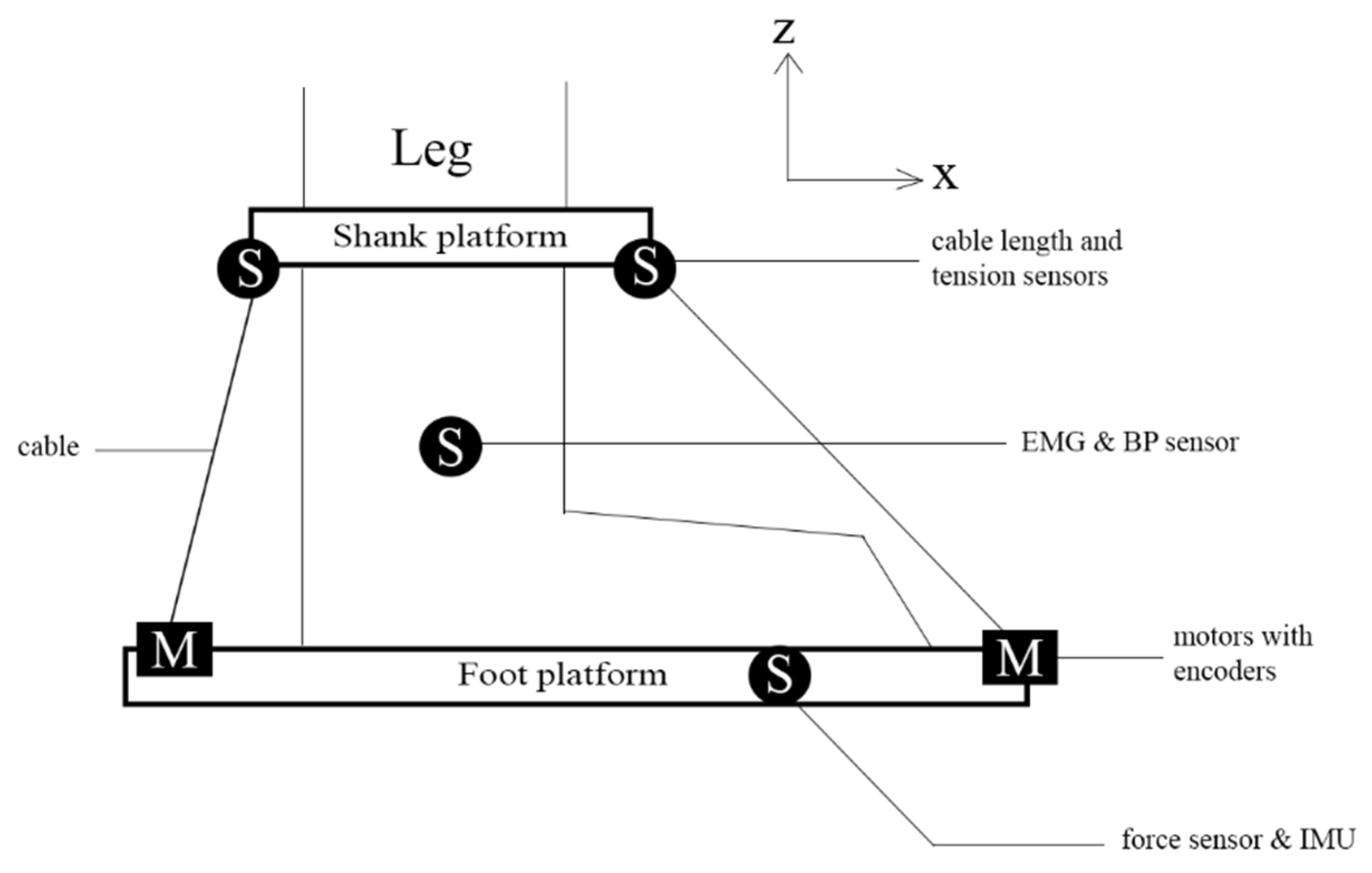
3. CABLEankle, an Ankle Assisting Device

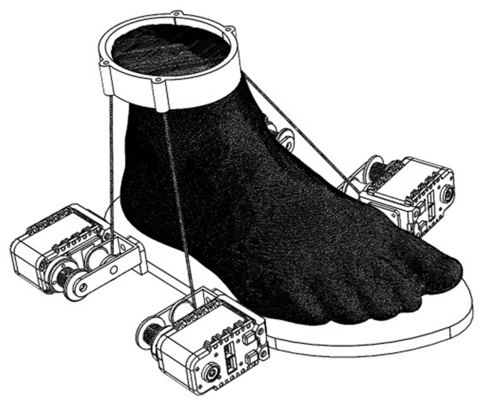
3.1. Mechanism Design of a Cable-Driven Assistive Device

The CABLEankle is a S-4SPS cable-driven parallel mechanism that functions as a lightweight wearable robot for ankle rehabilitation [32,33]. The ankle joint has three main motion modes—dorsiflexion/plantarflexion, abduction/adduction, and inversion/eversion. This device can accommodate the ankle joint motion along all the three motion modes but within a limited range, as described in Table 1 [27]. Four cables are used to achieve this triaxial motion, with the help of motors, according to the requirement of the patient. The motors help orient the foot platform with respect to the stationary shank platform, as shown in Figure 1 and Figure 2, and help provide motion assistance or guidance to the user.

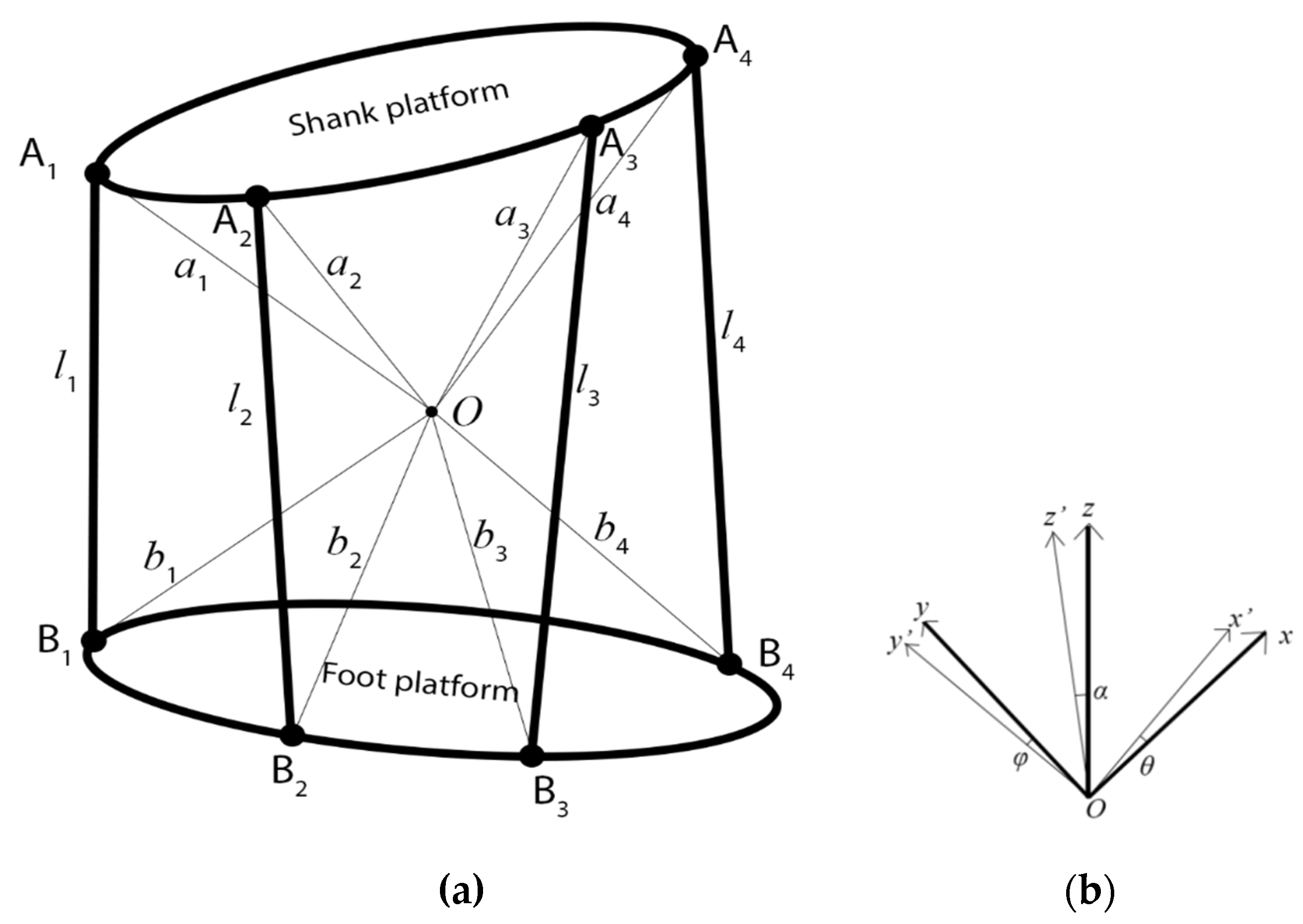
3.2. Kinematic Analysis

The CABLEankle device consists of two platforms, one at the base of the foot and the other at the shank of the patient. They are fastened to the patient by means of straps and can be considered as fixed to the patient’s leg. Their relative motion is here analysed by assuming the shank platform as fixed, while the foot platform can orient itself relative to the shank by varying the length of the cables connecting the two platforms. This relative motion of the foot platform happens about the ankle joint, whose kinematic behavior can be assumed to be a passive spherical joint with a restricted range of angular motion.
The shank platform is represented by a reference frame A contains Oxyz frame, while the reference frame B of the foot platform is given by Ox’y’z’, as seen in Figure 3. The relative motion of the foot platform with respect to the shank platform is a roll–pitch-–yaw motion that can be expressed as ABR = Rz(α) Ry(ϕ) Rx(θ), where ϕ measures dorsiflexion/plantarflexion, θ measures inversion/eversion, and α measures abduction/adduction. During the motion, three assumptions are followed: (i) all cables are always under tension, (ii) the points where the cable is attached to the platform act as spherical joints, and (iii) the cables are considered to be prismatic joints with negligible axial deformation.
The positions where the cables are attached can be generalized as A a i = ( a i x     a i y   a i z ) T at the shank platform and B b i = ( b i x     b i y   b i z ) T at the foot platform. Using the model in Figure 3, the vectorial loop-closure equation for each cable can be written as
l A i = R A B b B i a A i
where, li is the distance between the points Ai and Bi for the ith cable. The scalar product of either side of the (1) is multiplied by itself, and the length of each cable is expressed as
l i = a A i T a A i + b B i T b B i 2 a A i T R A B b B i

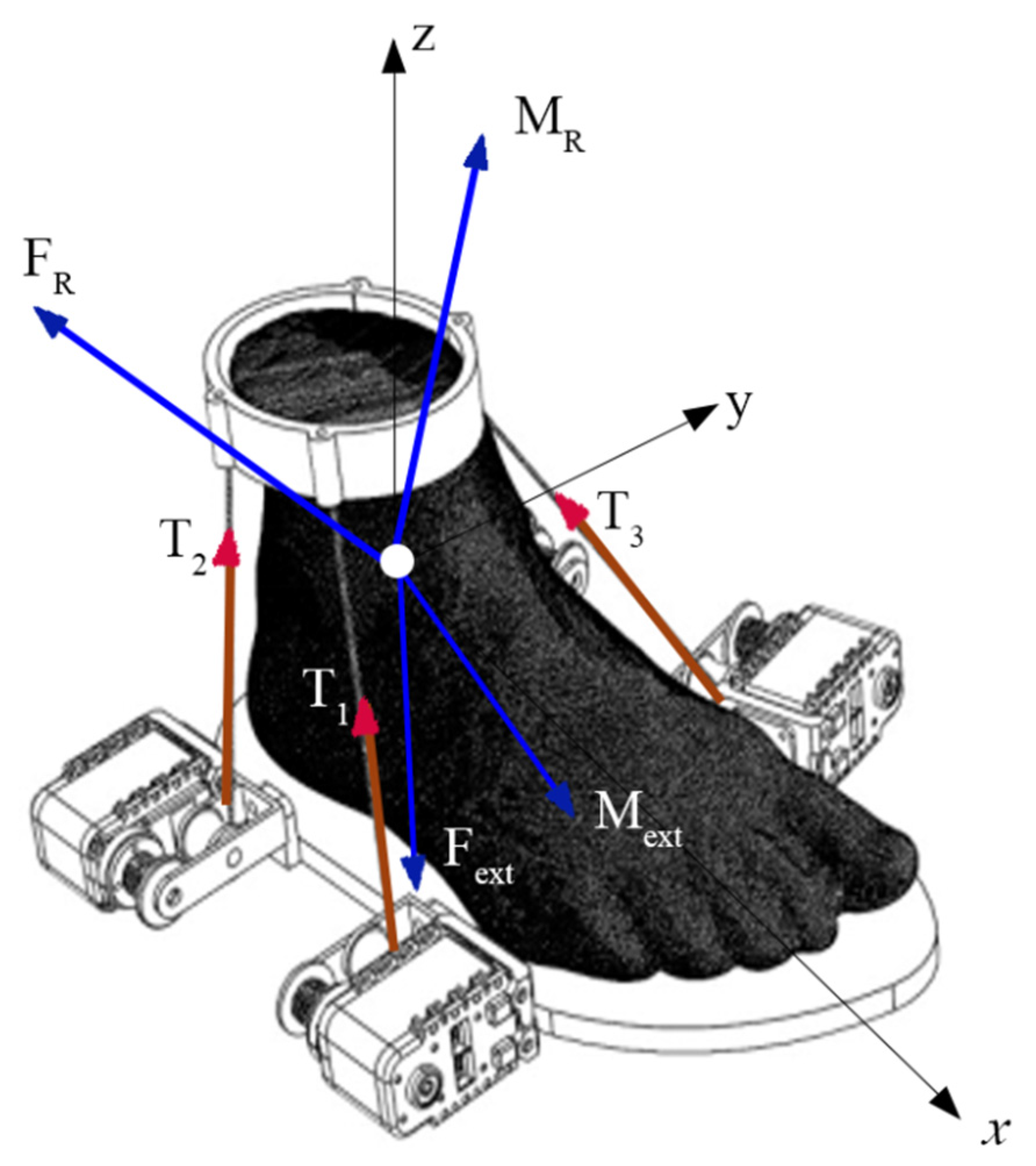
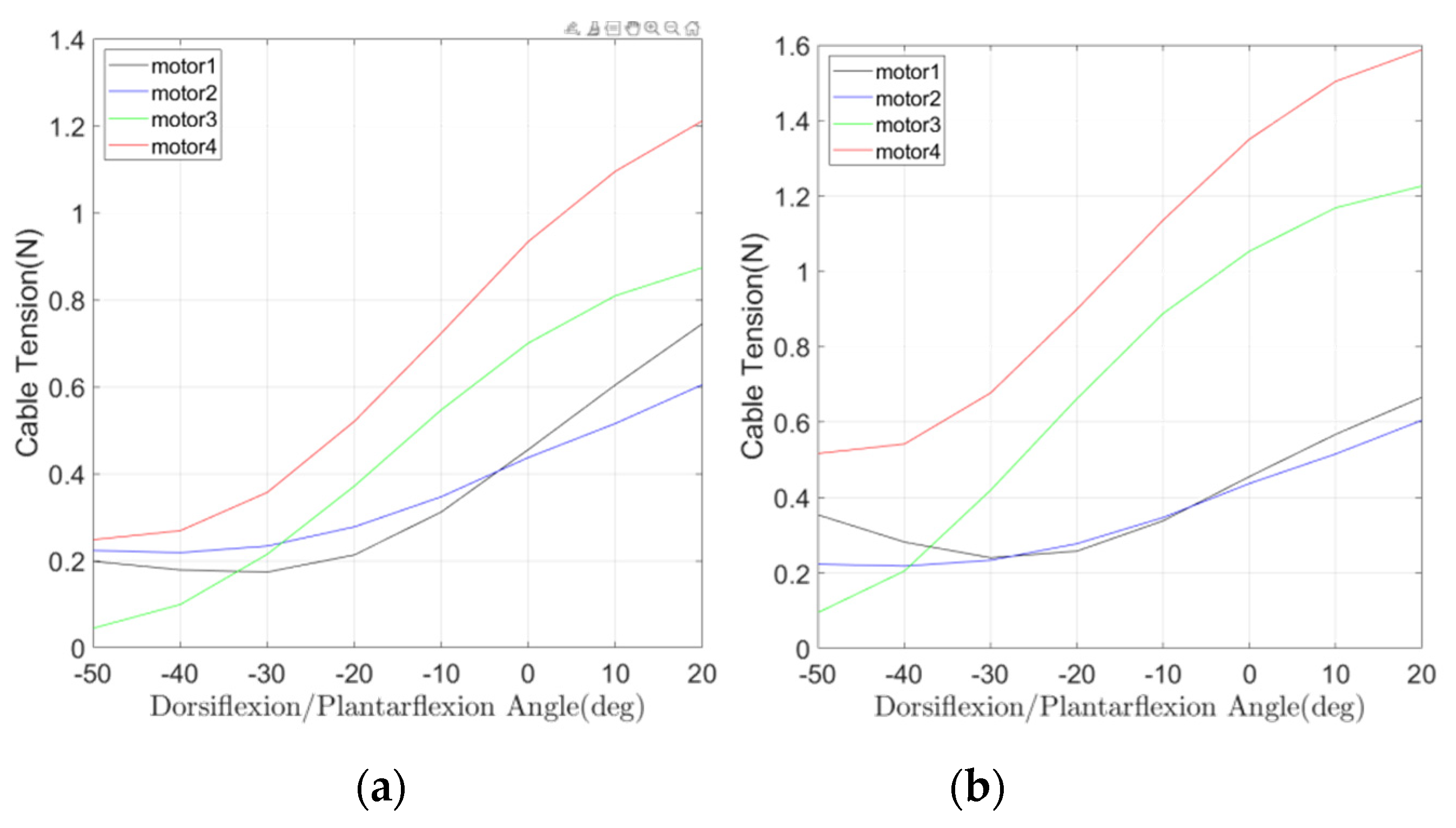
3.3. Static Analysis

Rehabilitation requires a smooth, slow, and controlled motion to ensure that minimal stress or pain is experienced by the patient. Since this mechanism is designed to operate with limited speed, inertial effects and dynamics can be neglected. Hence, a static analysis can be adopted for performance evaluation.
When an external wrench defined by force Fext and moment Mext is applied to the foot platform, static equilibrium is achieved through reactions such as tension T, reaction force FR, and reaction moment MR, as shown in Figure 4.
The equilibrium condition for translation in frame A can be expressed as
i = 1 n T i + F R + F e x t = 0
while the equilibrium condition for rotation is given by
i = 1 n b i × T i + M R + M e x t = 0
where Ti is the tension in the ith cable. The tension in each cable is expressed as the product of it’s magnitude and cable unit vector as Ti = −Ti pi, where the actuation vector T is defined as (T1 T2 T3 T4)T. Using this, Equations (3) and (4) can, respectively, be rewritten as
P T · T F R = F e x t
and,
Q T · T M R = M e x t
where, PT = [p1 p2 p3 p4] and QT = [b1 × p1b4 × p4].
As discussed previously, since the ankle joint’s kinematic behavior is assumed to be that of a spherical joint, rotational motion is not constrained within the limited range of the ankle joint and hence the reaction moment MR is considered a null vector. Hence, Equations (5) and (6) can be combined to represent the full equilibrium given by
[ P T I 3 Q T 0 3 ] ( T F R ) = ( F e x t   M e x t )
The operation problem can be characterized by solving the actuating torque as function of a prescribed ankle motion in controlled assisted exercise.

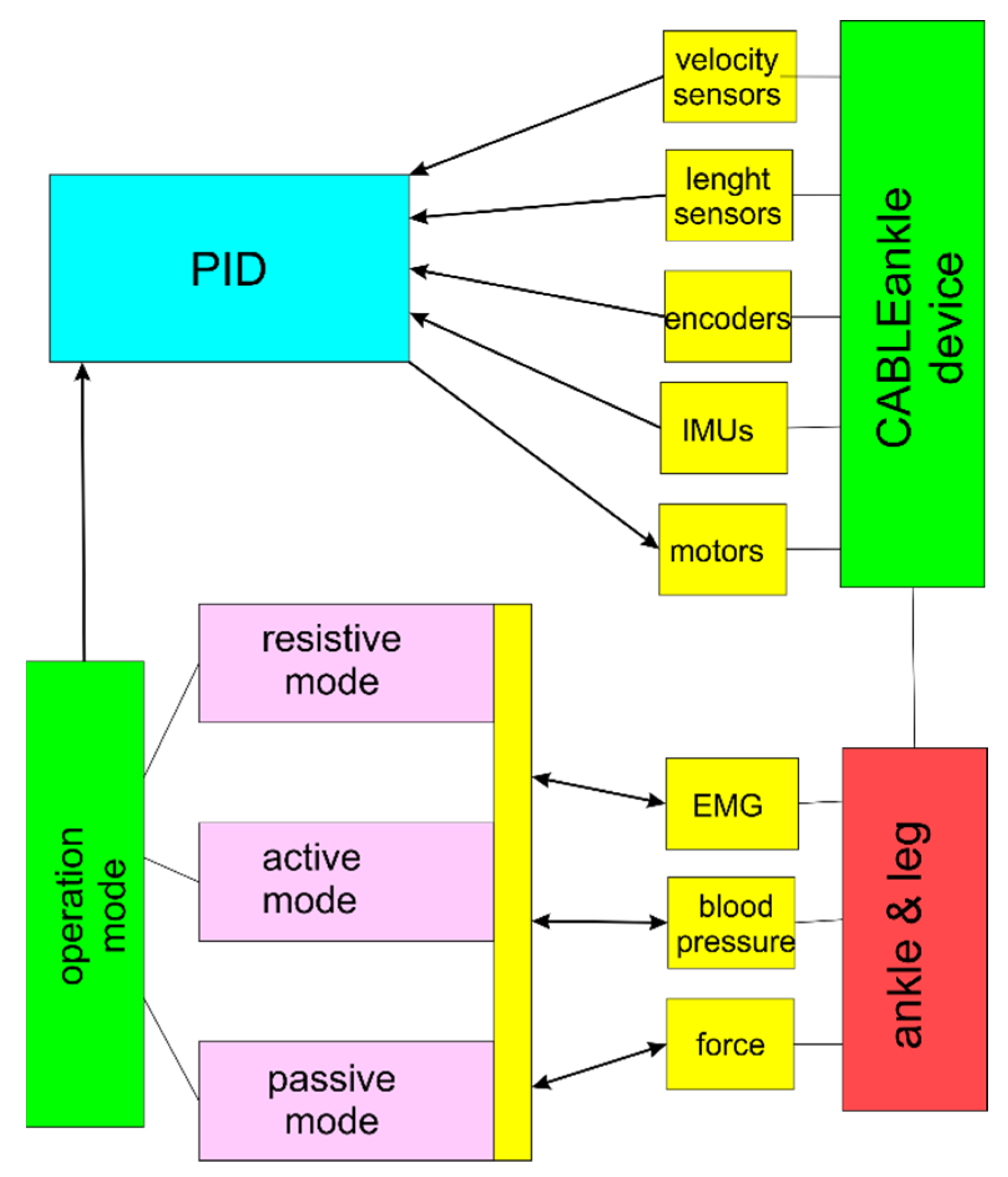
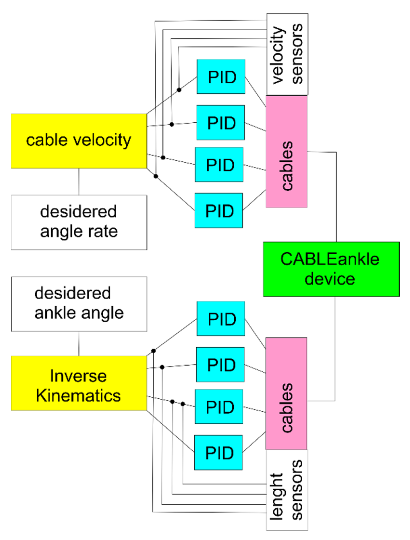
4. Solution for Control Design Unit

A complete control system for CABLEankle would involve both position and force control for achieving a desired position of the platform and a desired force and torque from the motors based on user input. The flowchart of such a control system design is provided in Figure 5. It is designed to incorporate two modes of rehabilitation, active and passive, for the efficient recovery of the patient.
Resistive mode and co-operative mode fall under the category of active rehabilitation. In resistive mode, a resistive torque is applied by the motors forcing the user to apply additional effort to move the platform. This mode causes a moment that opposes the force exerted by the muscles. Hence, it is especially used for increasing the strength of the joint. For the case of co-operative mode, any force exerted by the patient is understood as an intention to perform the motion in that direction, and torque is applied to assist that motion. On the other hand, passive mode rehabilitation is where only the motors perform all the work required to move the leg rested on the platform and no muscular activity is involved from the user’s side. These types of exercises are aimed at improving the flexibility of the joint. There are two main subcategories of passive exercises, relaxed and forced passive exercises. As noted earlier, joints have a set range of motion, and forced passive exercises force the joint to move a little beyond the limited range. Here, relaxed passive exercises that simply move the joint with the help of a motor are adopted since this work focuses on functioning within the limited range.
The remaining blocks in the flowchart in Figure 5 represent sensors that can be divided into two categories, namely, operation control and monitoring. Sensors such as motor encoder, IMU, and cable-length and cable-tension sensors fall under operation control sensors. They help to obtain information such as angular position/velocity, pose of the platform, length of the cable measured in real-time, and tension values in the cables to ensure they always satisfy the force-closure equation, respectively. In the other category are the force sensors that are placed on the platform to measure the force exerted by the patient and to determine the direction in which the user wants to rotate the platform. The EMG sensor is used to monitor the muscle activity in the region and provide information on the healing status of the ankle. Prior research in rehabilitation robotics has shown various successful ways in which EMG sensors could be used to monitor the muscular activity in the muscles surrounding the joint to measure the progress of the strength of the joint. A blood pressure sensor is used to monitor the blood pressure levels in the ankle region to monitor both for indicating patient reaction and patient safety since active exercises can cause a pressure increase that could be either a good signal or harmful after an ankle injury (e.g., avoid harmful increase in blood pressure in individuals with edema from the ankle injury as pointed out in [34]). In addition, this sensor is used only in the case of active rehabilitation because, in general, the mean average pressure does not change during passive rehabilitation.
In this work, a control framework is designed as in Figure 6 for passive and active-resistive modes with cable length sensors and cable velocity sensors as per the control feedback during dorsiflexion/plantarflexion. From the kinematic and static analysis in Section 2, it can be noted that cable length influences the tension in the cables and the load on the ankle and is also directly related to the flexion angle. Hence, it is chosen as the primary control input to achieve position control of the foot platform during ankle exercise. During the motion, errors could arise from physical inaccuracies in the mechanical components that are due mainly to parameter identification and tolerance in construction and assembly, and to deal with such scenarios, this framework is equipped with PID controllers to ensure that the actual cable length and velocity values are close enough to the desired values. Referring to Figure 6, the Inverse Kinematics block calculates the cable lengths taking the flexion angle as the input by using formulation in Section 2 with Equations (2) and (3). The Cable Velocity block outputs the cable velocities based on the rate of ankle pose, which can be computed yet by using a formulation. The data necessary to generate results for control design refer to the configuration in Table 2, with the design parameters that have been obtained through an optimization procedure that considers both design and path [33], and the control parameters tuned through Matlab Simulink. When a velocity control is implemented, the PID controller thus operates as per Figure 6 according to
l ˙ i ( t ) = K p l i , e r r ( t ) + K i   l i , e r r ( t ) d t + K d d l i , e r r ( t ) d t
where l ˙ i represents the velocity of the ith cable (i.e., its length variation over time), l i , e r r is the difference between the current and desired cable configuration, K p is the proportional gain of the controller, K i is the integral gain of the controller, and K d is the derivative gain of the controller. While this represents a way of controlling the proposed device, when other sensors are included (e.g., EMG, blood pressure, and force), their inputs can be implemented in the control scheme to better react to the patient’s behavior and improve the rehabilitation therapy.

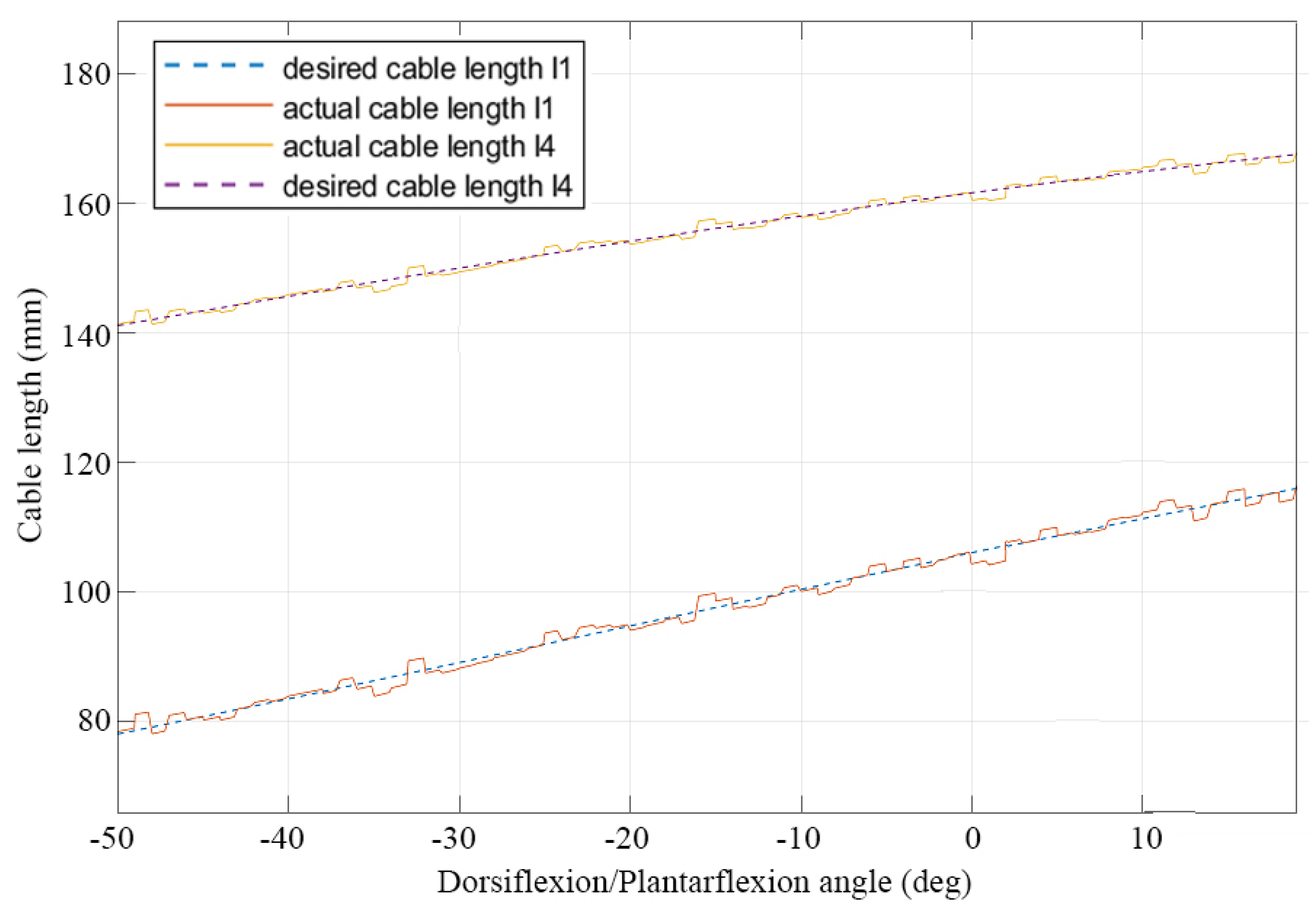
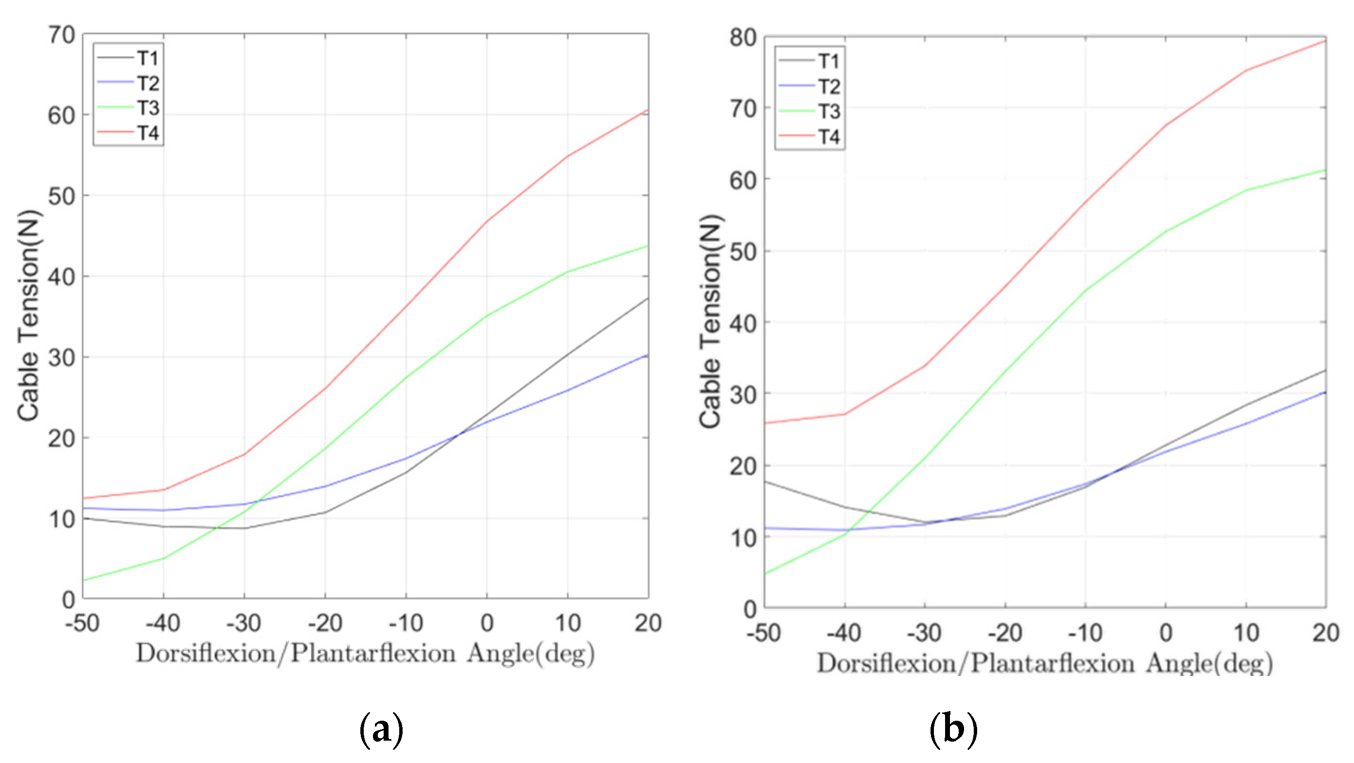
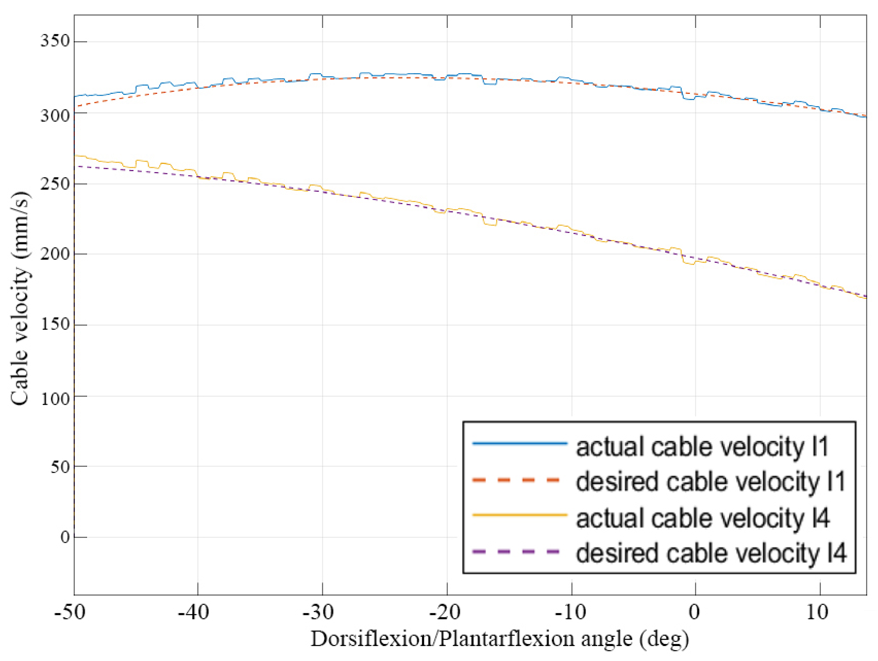
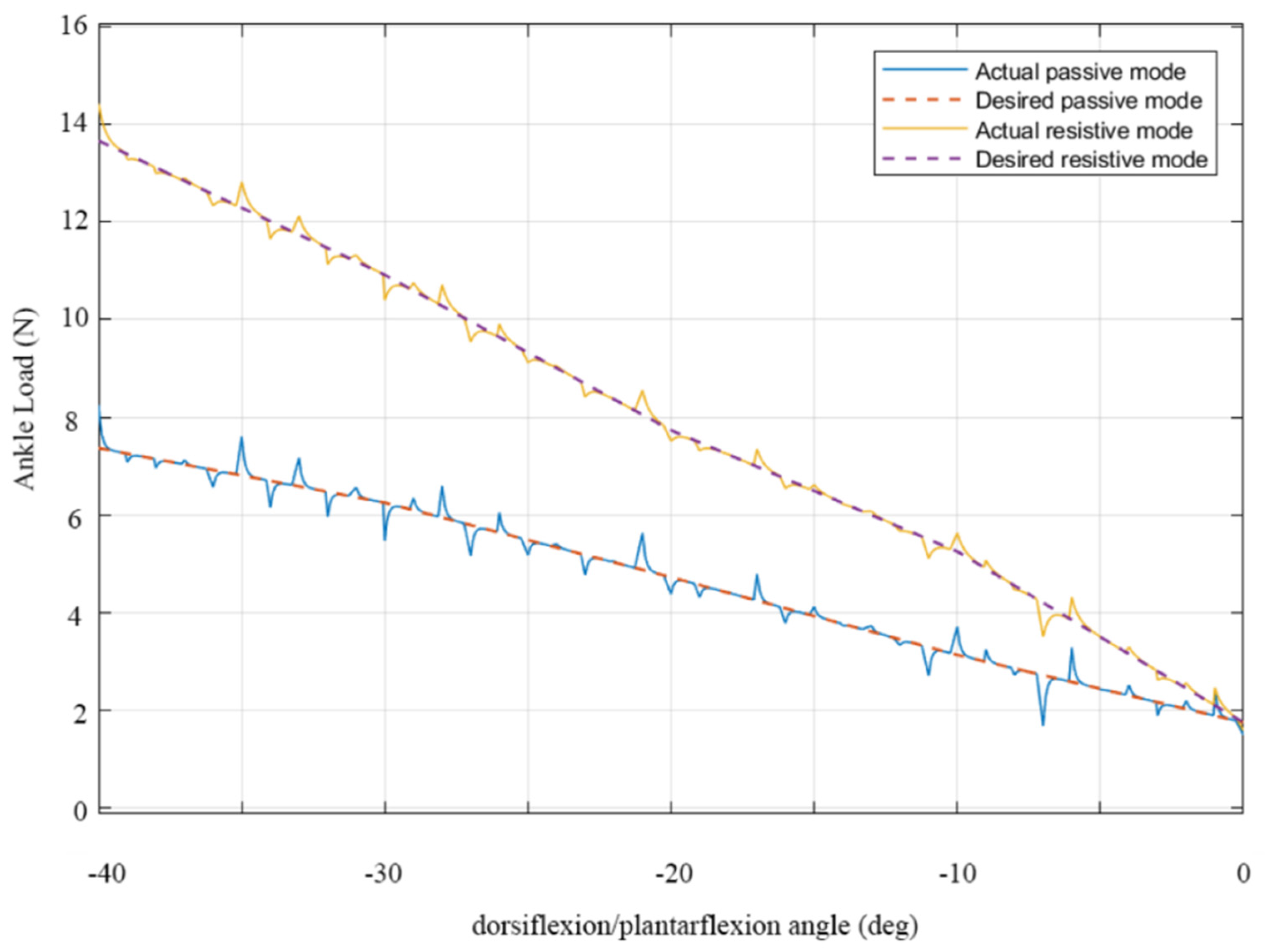
5. Performance Analysis

Based on the kinematic and static analysis performed in Section 2, the controller was designed referring to the scheme in Figure 6. Using Equation (2), the length of each cable can be computed for the simulated motion modes. The static analysis gives information about the cable tensions and reaction forces. These values have been computed for different inclinations of the mobile platform within the motion range of the ankle joint and for different rehabilitation modes such as resistive and passive. For the passive rehabilitation scenario, the cable tensions and motor torque are computed by assuming no external wrench being applied on the foot except for its own mass of 1 Kg. For the active resistive rehabilitation case, an external moment of 0.5 Nm is applied about the y-axis. The motor torques for the ith motor was calculated by multiplying the tension of the ith cable by the pulley diameter, which was assumed to be 0.02 m. The results of cable tensions and motor torques during dorsiflexion/plantarflexion are provided in Figure 7 and Figure 8.
The developed PID controller ensures that the position of the platform always reaches the desired inclination of the user by taking control variables such as cable length and velocity as inputs. The kinematic and static analysis shows a direct relationship between the control inputs and desired angle and rate of desired angle, respectively. Thus, it can be implied that reducing the error in the above control inputs would help achieve the desired flexion angle as well. Simulation has been carried out on a controlled operation for an example of dorsiflexion/plantarflexion assisted motion from 0° to 40°. Results are reported in Figure 9, Figure 10 and Figure 11 to characterize the designed control system for the device.
In particular, plots representing the desired and actual cable length and velocity values are shown in Figure 9 and Figure 10. It can be noted that, with the proposed controller, the system is able to achieve a stable behaviour, which closely follows the desired one, with a maximum error of 2 mm throughout the full range of motion over dorsiflexion/plantarflexion exercises.
Apart from achieving the desired angle of inclination of the foot platform, it is equally important to pay attention to the ankle load. The developed controller also provides information about the force on the ankle, as illustrated in the results in Figure 11 for the same exercise reported in Figure 9 and Figure 10. The graph reports the results from two different control modes: the upper line represents the forces in resistive mode, when the user has to overcome an additional load from the rehabilitation device, while the lower line characterizes functioning in passive mode, with the device fully supporting and controlling the ankle of the patient throughout a rehabilitation exercise.
For the case of dorsiflexion/plantarflexion, it can be observed that, as the ankle moves from 0° to −40°, there is a visible increase in the load on the joint for both functioning modes. This is expected, as the foot moves from its “resting” position to a more “uncomfortable” one and thus requires effort to sustain the resulting bent position. For the passive control mode, this increase goes from 2 N to less than 8 N, which is a safe value for an injured ankle and can be used in early rehabilitation stages to avoid straining the joint further. Conversely, the increase is steeper for the resistive mode, imposing a load up to 14 N, suggesting that the ankle is being compelled to apply a force to counteract the resistive torque from the cables and motors. This higher load is more suited to later stages of rehabilitation or daily exercising.
When compared to the expected load for the ideal motion, which can be computed with Equation (7), the load on the joint relative to the control simulation in Figure 9 and Figure 10 presents a less smooth behaviour with local force peaks. Nevertheless, these fluctuations are always within 1 N, and the overall load on the joint never reaches a critical threshold throughout the whole rehabilitation exercise, thus validating the proposed control.

6. Discussion

The results in Figure 7 and Figure 8 show for the motion of dorsiflexion/plantarflexion that the maximum cable tension values are less than 90 N for both passive and active resistive rehabilitation cases. Thus, with an appropriate pulley design, the device can operate without reaching the servo motor’s upper limit for the ankle’s whole range of motion as planned in a full exercise [27].
Apart from the motor limits, the results in Figure 9 and Figure 10 show the error between the computed and desired cable length and velocity values that implies achieving position control of the angle of inclination of the foot platform, which is necessary for the safe operation with a patient. These values, upon being extended to find the load on the ankle joint as reported in Figure 11, confirm the validity of both active and passive rehabilitation modes. From these results, it can be noted that this solution satisfies the requirement and solves the problems mentioned in Section 3. As such, the proposed robot can be successfully used to perform rehabilitation for both early treatment of an injury (in passive mode, thanks to the limited load imposed on the ankle in this more critical phase) and later daily exercises (in resistive mode, when the added load helps the patient exercise ankle muscles and recover full mobility and strength).
Even though the requirements have been met, advances can still be made to provide a user with more flexibility and to equip the controller with more control parameters for achieving improved monitoring and operation functionalities. The designed control framework presented in this work considers only cable length and cable velocity. However, as mentioned in the general design scheme in Section 4, future work could include utilizing IMUs, force sensors, blood pressure sensors, and EMG sensors in order to build a more complete controller. Typically, EMG sensors are used just for monitoring purposes, but it would be interesting to utilize them along with the feedback loop to take in motor control commands based on myoelectric signals and deliver them to the PID controller so that the rehabilitation device could better react to the patient’s behaviour during therapy and provide an overall better rehabilitation experience.
Overall, the control system introduced in this manuscript integrates previous hardware with novel software capability and functionality, providing an adaptive control that can evaluate and apply actuation forces and torques as required from different stages of ankle rehabilitation and assistance while ensuring safe operation within the physical limits of a patient. In particular, the proposed controller is able to assist users in both passive and active exercise, by either controlling the load on the ankle, increasing it to a desired value for strengthening exercises, or supporting and guiding ankle motion in earlier rehabilitation phases. While the performance of the proposed system has been evaluated through simulations, future works will focus on prototype development and experimental validations on both healthy subjects and people with limited ankle mobility.

Author Contributions

Conceptualization, I.V.S.P., M.C. and M.R.; methodology, I.V.S.P. and M.C.; software, I.V.S.P.; validation, I.V.S.P.; formal analysis, I.V.S.P. and M.C.; investigation, I.V.S.P., M.C. and M.R.; resources, M.C.; data curation, I.V.S.P.; writing—original draft preparation, I.V.S.P. and M.C.; writing—review and editing, I.V.S.P., M.R. and M.C.; visualization, I.V.S.P.; supervision, M.C.; project administration, M.C.; funding acquisition, M.C. All authors have read and agreed to the published version of the manuscript.

Funding

This research received no external funding.

Conflicts of Interest

The authors declare no conflict of interest.

References

  1. Wang, C.; Wang, L.; Wang, T.; Li, H.; Du, W.; Meng, F.; Zhang, W. Research on an Ankle Joint Auxiliary Rehabilitation Robot with a Rigid-Flexible Hybrid Drive Based on a 2-S′PS′ Mechanism. Appl. Bionics Biomech. 2019, 2019, 7071064. [Google Scholar] [CrossRef] [Green Version]
  2. Brockett, C.L.; Chapman, G.J. Biomechanics of the ankle. Orthop. Trauma 2016, 30, 232–238. [Google Scholar] [CrossRef] [Green Version]
  3. Knudson, D. Fundamentals of Biomechanics; Springer Science & Business Media: Berlin/Heidelberg, Germany, 2007. [Google Scholar]
  4. Mattacola, C.G.; Dwyer, M.K. Rehabilitation of the Ankle After Acute Sprain or Chronic Instability. J. Athl. Train. 2002, 37, 413–429. [Google Scholar]
  5. Chen, E.T.; McInnis, K.C.; Borg-Stein, J. Ankle sprains: Evaluation, rehabilitation, and prevention. Curr. Sports Med. Rep. 2019, 18, 217–223. [Google Scholar] [CrossRef]
  6. Chinn, L.; Hertel, J. Rehabilitation of Ankle and Foot Injuries in Athletes. Clin. Sports Med. 2010, 29, 157–167. [Google Scholar] [CrossRef] [Green Version]
  7. Nagaya, S.; Hayashi, H.; Fujimoto, E.; Maruoka, N.; Kobayashi, H. Passive ankle movement increases cerebral blood oxygenation in the elderly: An experimental study. BMC Nurs. 2015, 14, 14. [Google Scholar] [CrossRef] [Green Version]
  8. Díaz, I.; Gil, J.J.; Sánchez, E. Lower-Limb Robotic Rehabilitation: Literature Review and Challenges. J. Robot. 2011, 2011, 759764. [Google Scholar] [CrossRef]
  9. Zhang, M.; Davies, T.C.; Xie, S. Effectiveness of robot-assisted therapy on ankle rehabilitation–a systematic review. J. Neuroeng. Rehabil. 2013, 10, 30. [Google Scholar] [CrossRef] [Green Version]
  10. Alvarez-Perez, M.G.; Garcia-Murillo, M.A.; Cervantes-Sánchez, J.J. Robot-assisted ankle rehabilitation: A review. Disabil. Rehabil. Assist. Technol. 2020, 15, 394–408. [Google Scholar] [CrossRef]
  11. Miao, Q.; Zhang, M.; Wang, C.; Li, H. Towards Optimal Platform-Based Robot Design for Ankle Rehabilitation: The State of the Art and Future Prospects. J. Health Eng. 2018, 2018, 1534247. [Google Scholar] [CrossRef]
  12. Yoon, J.; Ryu, J.; Lim, K.-B. Reconfigurable ankle rehabilitation robot for various exercises. J. Robot. Syst. 2006, 22, S15–S33. [Google Scholar] [CrossRef]
  13. Jamwal, P.K.; Hussain, S.; Ghayesh, M.H.; Rogozina, S.V. Impedance Control of an Intrinsically Compliant Parallel Ankle Rehabilitation Robot. IEEE Trans. Ind. Electron. 2016, 63, 3638–3647. [Google Scholar] [CrossRef]
  14. Saglia, J.A.; Tsagarakis, N.G.; Dai, J.S.; Caldwell, D.G. Control Strategies for Patient-Assisted Training Using the Ankle Rehabilitation Robot (ARBOT). IEEE/ASME Trans. Mechatron. 2013, 18, 1799–1808. [Google Scholar] [CrossRef]
  15. Roy, A.; Krebs, H.I.; Williams, D.J.; Bever, C.T.; Forrester, L.W.; Macko, R.M.; Hogan, N. Robot-Aided Neurorehabilitation: A Novel Robot for Ankle Rehabilitation. IEEE Trans. Robot. 2009, 25, 569–582. [Google Scholar] [CrossRef]
  16. Rodríguez-León, J.F.; Chaparro-Rico, B.D.M.; Russo, M.; Cafolla, D. An Autotuning Cable-Driven Device for Home Rehabilitation. J. Health Eng. 2021, 2021, 6680762. [Google Scholar] [CrossRef]
  17. Sung, E.; Slocum, A.H.; Ma, R.; Bean, J.F.; Culpepper, M.L. Design of an Ankle Rehabilitation Device Using Compliant Mechanisms. J. Med. Devices 2011, 5, 011001. [Google Scholar] [CrossRef] [Green Version]
  18. Fan, Y.; Yin, Y. Mechanism design and motion control of a parallel ankle joint for rehabilitation robotic exoskeleton. In Proceedings of the 2009 IEEE International Conference on Robotics and Biomimetics (ROBIO), Guilin, China, 19–23 December 2009; Institute of Electrical and Electronics Engineers (IEEE): Piscataway, NJ, USA; pp. 2527–2532. [Google Scholar]
  19. Lin, C.C.; Ju, M.S.; Chen, S.M.; Pan, B.W. A specialized robot for ankle rehabilitation and evaluation. J. Med. Biol. Eng. 2008, 28, 79–86. [Google Scholar]
  20. Chang, T.-C.; Zhang, X.-D. Kinematics and reliable analysis of decoupled parallel mechanism for ankle rehabilitation. Microelectron. Reliab. 2019, 99, 203–212. [Google Scholar] [CrossRef]
  21. Nurahmi, L.; Caro, S.; Solichin, M. A novel ankle rehabilitation device based on a reconfigurable 3-RPS parallel manipulator. Mech. Mach. Theory 2019, 134, 135–150. [Google Scholar] [CrossRef] [Green Version]
  22. Park, Y.-L.; Chen, B.-R.; Pérez-Arancibia, N.O.; Young, D.; Stirling, L.; Wood, R.J.; Goldfield, E.C.; Nagpal, R. Design and control of a bio-inspired soft wearable robotic device for ankle–foot rehabilitation. Bioinspir. Biomim. 2014, 9, 016007. [Google Scholar] [CrossRef]
  23. Liu, Q.; Zuo, J.; Zhu, C.; Meng, W.; Ai, Q.; Xie, S.Q. Design and Hierarchical Force-Position Control of Redundant Pneumatic Muscles-Cable-Driven Ankle Rehabilitation Robot. IEEE Robot. Autom. Lett. 2021, 7, 502–509. [Google Scholar] [CrossRef]
  24. Dong, M.; Zhou, Y.; Li, J.; Rong, X.; Fan, W.; Zhou, X.; Kong, Y. State of the art in parallel ankle rehabilitation robot: A systematic review. J. Neuroeng. Rehabil. 2021, 18, 52. [Google Scholar] [CrossRef] [PubMed]
  25. Cafolla, D.; Russo, M.; Carbone, G. Design and Validation of an Inherently-Safe Cable-Driven Assisting Device. Int. J. Mech. Control. 2018, 19, 23–32. [Google Scholar]
  26. Aggogeri, F.; Pellegrini, N.; Adamini, R. Functional Design in Rehabilitation: Modular Mechanisms for Ankle Complex. Appl. Bionics Biomech. 2016, 2016, 9707801. [Google Scholar] [CrossRef] [Green Version]
  27. Dai, J.S.; Zhao, T.; Nester, C. Sprained Ankle Physiotherapy Based Mechanism Synthesis and Stiffness Analysis of a Robotic Rehabilitation Device. Auton. Robot. 2004, 16, 207–218. [Google Scholar] [CrossRef]
  28. Liu, Q.; Wang, C.; Long, J.J.; Sun, T.; Duan, L.; Zhang, X.; Zhang, B.; Shen, Y.; Shang, W.; Lin, Z.; et al. Development of a New Robotic Ankle Rehabilitation Platform for Hemiplegic Patients after Stroke. J. Health Eng. 2018, 2018, 3867243. [Google Scholar] [CrossRef] [Green Version]
  29. Russo, M.; Ceccarelli, M. Analysis of a Wearable Robotic System for Ankle Rehabilitation. Machines 2020, 8, 48. [Google Scholar] [CrossRef]
  30. Wang, Y.; Wang, K.; Zhang, Z.; Mo, Z. Control strategy and experimental research of a cable-driven lower limb rehabilitation robot. Proc. Inst. Mech. Eng. Part C J. Mech. Eng. Sci. 2021, 235, 2468–2481. [Google Scholar] [CrossRef]
  31. Oyman, E.L.; Korkut, M.Y.; Ylmaz, C.; Bayraktaroglu, Z.Y.; Arslan, M.S. Design and control of a cable-driven rehabilitation robot for upper and lower limbs. Robotica 2021, 40, 1–37. [Google Scholar] [CrossRef]
  32. Russo, M.; Ceccarelli, M. A Wearable Device for Ankle Motion Assistance. In Advances in Italian Mechanism Science; Springer: Berlin, Germany, 2020; pp. 173–181. [Google Scholar] [CrossRef]
  33. Russo, M.; Raimondi, L.; Dong, X.; Axinte, D.; Kell, J. Task-oriented optimal dimensional synthesis of robotic manipulators with limited mobility. Robot. Comput. Manuf. 2021, 69, 102096. [Google Scholar] [CrossRef]
  34. Cloughley, W.B.; Mawdsley, R.H. Effect of Running on Volume of the Foot and Ankle. J. Orthop. Sports Phys. Ther. 1995, 22, 151–154. [Google Scholar] [CrossRef] [PubMed]
Figure 1. Conceptual design of CABLEankle.
Actuators 11 00063 g001
Figure 2. CAD design of CABLEankle as in [27].
Actuators 11 00063 g002
Figure 3. (a) Kinematic scheme with motion variables and (b) reference frames.
Actuators 11 00063 g003
Figure 4. Static model of CABLEankle.
Actuators 11 00063 g004
Figure 5. A scheme for control design in CABLEankle device.
Actuators 11 00063 g005
Figure 6. Flowchart of the designed control system for CABLEankle device.
Actuators 11 00063 g006
Figure 7. Computed cable tensions during a simulated controlled operation: (a) in passive mode and (b) in active resistive mode.
Actuators 11 00063 g007
Figure 8. Computed motor torques during a simulated controlled operation: (a) in passive mode and (b) in active resistive mode.
Actuators 11 00063 g008
Figure 9. Desired and computed cable length values for a simulated operation of a controlled ankle assisted motion exercise.
Actuators 11 00063 g009
Figure 10. Desired and computed cable velocity values for a simulated operation of a controlled ankle assisted motion exercise.
Actuators 11 00063 g010
Figure 11. Desired and computed ankle load for simulated passive and resistive modes values of a controlled ankle assisted motion exercise.
Actuators 11 00063 g011
Table 1. Ranges of motion of the human ankle joint [1,2,3].
MotionDorsiflexionPlantarflexionAbduction/AddjuctionInversion/Eversion
Range Limits20 deg50 deg+/−10 deg+/−12 deg
Table 2. Parameters of performance evaluation for the control design.
Shank Platform (mm)Foot Platform (mm)Control Parameters
a A 1 = (20 30 50)T b B 1 = (80 75 −40)Tli ∈ [20 mm, 200 mm]
ϕ ∈ [−50°, 20°]
a A 2 = (−20 30 50)T b B 2 = (0 60 −40)T K p = 0.1
a A 3 = (20 −30 50)T b B 3 = (10 60 −40)T   K i = 1
a A 4 = (−20 −30 50)T b B 4 = (90 60 −40)T K p = 0.001
Publisher’s Note: MDPI stays neutral with regard to jurisdictional claims in published maps and institutional affiliations.

