1. Introduction
With the increasing demands for the high performance of motion control systems, advanced control strategies have been applied to the motor drives. For parametric uncertainties, model uncertainties, unknown dynamics, and disturbances, the unknown elements of the dynamics and disturbances need to be estimated and compensated to improve accuracy. During the past several decades, disturbance/uncertainty estimation and attenuation techniques have received considerable attention in mechanical drives [
1], including the disturbance observer (DOB) [
2,
3], unknown input observer (UIO) [
4], equivalent input disturbance (EID)-based estimator [
5], extended state observer (ESO), etc. [
6,
7,
8,
9,
10]. The mathematical model of the servo system is not accurate with unknown dynamics and uncertainties, but the disturbance observer methods need a precise model of the plant. Among the previously listed approaches, ESO does not require precise information of the plant; the internal dynamics and external disturbance are treated as total disturbance which could be estimated by ESO and compensated for the plant in real time by an active disturbance rejection controller (ADRC) [
11]. ESO is the key part of ADRC, which has been applied in solving a number of industry problems [
12,
13,
14,
15,
16,
17]. This control strategy draws the information needed to control the plant from ESO, instead of depending on the accurate model of the plant. For system uncertainties, variant load and noise, the disturbance must be estimated and compensated to improve system performance.
The load torque and moment of inertia are variable with the motion of robotic joint; however, the moment of inertia parameter in the nominal model of the servo system is constant. In this paper, the moment of inertia and load torque are variable in the model to approach the practical plant in which the total disturbance is estimated and rejected by ADRC to improve system performance. ADRC is an unconventional design strategy, which can actively estimate and compensate for the effects of unknown dynamics and uncertainties in real time. As some of the advantages of ADRC include not requiring a precise model, rejecting disturbance actively, etc., this control method is widely applied in motor servomechanisms [
18,
19], two-mass actuator systems [
20], robotic manipulators [
21], etc. Texas Instruments have developed motion control chips based on ADRC technology [
22]. The existing research has indicated that the linear extended state observer (LESO) is extremely simple and practical for system control when tuning only one parameter observer bandwidth [
23]. LESO has been applied in mechatronic systems with improving the system performance [
20].
The Kalman filter (KF) is the minimum-variance linear state estimator for linear dynamic systems with Gaussian noise [
24]. In a practical system, there are random noises in sensor measurement and plant running processes. In order to reduce noise, the Kalman filter and various modifications of the Kalman filter are important methods to restrain noise disturbance. The modifications include the extended Kalman filter, the unscented Kalman filter, and the particle filter, which are widely used in target tracking, robotics, navigation, state estimation of the servo system, and others [
25]. Since the error of the position sensor can be regarded as Gaussian white noise, the optimal estimation of the speed can be obtained by the Kalman the Filter from a series of position signals with noise [
26], so that the Kalman filter could improve system performance by reducing measurement noise.
The objective of this paper was to design a controller based on ADRC and the Kalman filter to improve performance of a servo system of which the moment of inertia is variable. The designed controller was based on variable gain obtained by the estimated inertia and the LESO with the measurement noise reduced by KF. The model was constructed with variable load torque and moment of inertia in real time. Due to the common controller PID causing the large overshoot of output, a tracking differentiator (TD) was used to approximate the system position and speed for reducing output overshoot. This paper is organized as follows. The dynamics of the servomechanism with variable moment of inertia is described in
Section 2. In
Section 3, the proposed controller based on the LESO and the Kalman filter is presented. The experiment verification is presented in
Section 4. Finally, some concluding remarks are given in
Section 5.
2. Dynamic Model of the Servomechanism
The dynamics of servomechanism is considered as:
where
x1 is the angular position of load,
x2 is the angular velocity of load,
x = [
x1,
x2]
T,
y is the measured position of load,
u is the control input, Bm is the viscous friction coefficient of motor side,
Jm(
t) is the variable moment of inertia of the system, which has been converted to the motor side,
Kt is the torque coefficient,
i is the reduction ratio,
dm(
x,
t) includes the uncertain dynamics and external disturbance viewed as total disturbance converted to motor side, and
n(
t) is the measurement noise.
Bm and Kt are treated as constant in the model while the moment of inertia Jm(t) is variable during the servomechanism motion. Variable feature of Jm(t) is considered as similar to the variance of cosine function according to the rotation characteristic of the robotic joint inertia. Load toque is also variable, which is set as a similar cosine function.
As we know, reference signals are often given as a step function causing the control signal step, and making the output largely overshoot. In order to reduce the output overshoot, tracking differentiator is applied to approximate to input position signal and velocity. Consider
x1d as the input signal of angular position, the tracking differentiator [
11] is written as
where
v1 is the output position of the tracking differentiator and
v2 is its derivative,
e0 is the tracking error,
h is the time step,
r0 is the parameter related to tracking speed, and function fhan (
e0,
v2,
r0,
h) is
Function fhan makes (2) be a time-optimal solution that guarantees fastest convergence from v1 to x1d without any overshoot.
The block diagram of the motion control system is illustrated in
Figure 1. As shown in the
Figure 1, the LESO is the designed observer, KF is the designed Kalman filter used to reduce measurement noise,
x1d is the reference signal,
u0 is the control law without disturbance compensation,
u is the control strategy,
z3 is the estimation of the extended state variable obtained by the LESO, representing the effect of the total disturbance, and
is the angular position with noise suppression by KF. The moment of inertia of the system
Jm(
t) is variable,
v1 is tracking
x1d, and
e is the error of system.
For motion control system-like robots, the moment of inertia
Jm(
t) is not a constant, varying with the robotic joint motion in real time. Consequently, we need to estimate
Jm(
t). As
x1 is the angular position of load,
x2 is the angular velocity of load, and
TL is the load torque converted to the motor side; neglecting unknown disturbance, from system (1) we can obtain:
and define
.
From (4), we obtain:
where
T is the sample time,
k = 0, 1, 2…
Define
,
, substituting into (5), and its discrete form is:
The estimation error is:
where
is the estimation of
.Define ,
where m is the amount of sample period.
The error evaluation function
is:
where
is the weight matrix,
,
,
i = 1, 2,…
m, and
is the confidence weight of testing value in
ith order.
The recursive least square method is:
where
is the estimation value at time
mT;
is the testing value at time (
m + 1)
T, which could be obtained by (5);
is the estimation error;
is the gain matrix update;
;
wm+1 is the (
m + 1)th order weight of
,
m = 0, 1, 2…
So, we can obtain which is the estimation value of Jm(t) from (10), for Jm(t) is varying with the robotic joint motion.
3. Controller Design Based on LESO and KF
3.1. Kalman Filter
Considering the process noise and measurement noise, and in order to obtain precise state values of the system, the Kalman filter is applied to filter the system noise. System (1) can be written as:
where
,
,
,
,
x = [
x1,
x2]
T,
.
System (11) is written as following discrete form:
where
,
is the state vector at time
, and
, respectively,
is the input control variable at time
,
I is the identity matrix, and
is the measurement.
Define
,
, the discrete equation of the system (11) is:
where
is the system noise with covariance
Q,
is measurement noise with covariance
R, and the Kalman filter equations are given as:
for
k = 1, 2, …, where
is the a priori estimate of the state
,
is the a posteriori estimate of the state
,
is the Kalman gain,
is the covariance of the a priori estimation error
, and
is the covariance of posteriori estimation error
. The Kalman filter is initialized with:
where E(·) is the expectation operator.
3.2. LESO Design
The linear extended state observer (LESO) is widely used to estimate states of the system and the extended state could represent the total disturbance [
23]. The extended state form of the motion control system (1) is:
where
is the extended state, which is also the effect of the total disturbance, and
x3 is differentiable.
The LESO of the system (21) is designed as:
where
z = [
z1,
z2,
z3]
T is the estimation of the system extended states
x = [
x1,
x2,
x3]
T, which is obtained by LESO, and
li,
i = 1, 2, 3, are the observer gain parameters to be designed.
The characteristic polynomial of (22) is
,
li,
i = 1, 2, 3, are selected to make (22) be Hurwitz. For simplicity, let:
From (23), we obtain , , . Here, is the observer bandwidth, which is the only tuning parameter of LESO, > 0.
Theorem 1. Assuming h(x,t) is bounded, there exists such that , i = 1, 2, 3.
Proof. Since
h(
x,
t) is bounded, there exists positive constant D such that
. Define estimation error
,
i = 1, 2, 3. From (21) and (22), the observer estimation error is:
(24) can be written as:
where
,
,
.
Solving (25), we can obtain:
From (25), matrix
A has three same eigenvalues
, then there exists constant
K > 0, such that:
Combining (27), (28) and (29) yields:
So, there exists constant M > 0, such that , i = 1, 2, 3. □
From (30), we can obtain that the larger the observer bandwidth ωo is, the more accurate the states estimation will be. If ωo is chosen as the suitable value, will approximate to , i = 1, 2, 3.
3.3. Controller Design
Due to the large overshoot of the system output when the input signal is the step function, a tracking differentiator is used to reduce the overshoot, as mentioned before. The system error is the tracking differentiator output v1, subtracting the system angular position.
The control law is designed as:
Substituting (31) into (21), the system is described as a cascade integral form:
where
u0 is designed as the linear controller.
Define as the position estimation of y by the Kalman filter, i.e., system output reducing the measurement noise by filtering.
Let:
where
and
are the controller gain parameters.
Define .
Combining (33) with (32) yields:
and
are selected to make
Hurwitz, then
. For simplicity, let:
so
,
, where
is the controller bandwidth, which is the only tuning parameter of the controller.
should be adjusted based on the requirements of performance and stability margin.
Substituting (33) into (31), ADRC control law is given by:
4. Experiment Verification
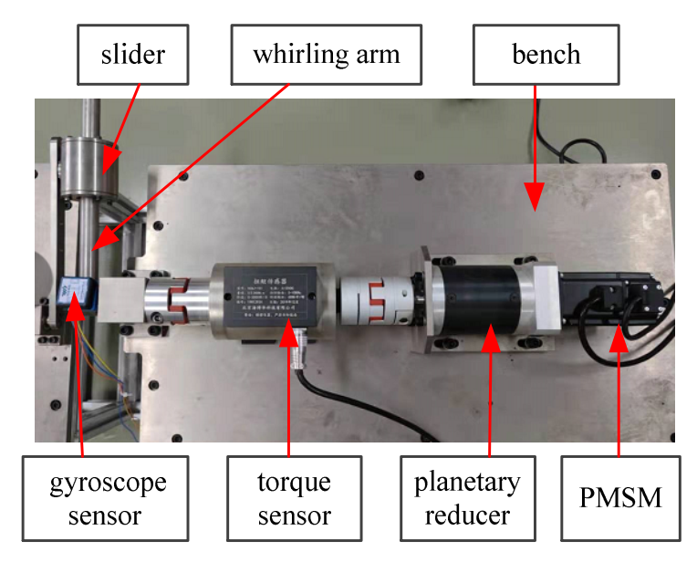
In this section, the robotic joint servo system is investigated to verify the effectiveness of the proposed control strategy. We developed an experimental platform with variable load, which consisted of a slider and a whirling arm. The inertia of the load varied when the slider moved, changing the distance between the slider and the center of the whirling arm. The verification platform for the motion control system was set up in
Figure 2. The gyroscope sensor was used to measure the actual position of the whirling arm with the slider. The torque sensor was applied to measure load torque, which was used to estimate the inertia of the load. The permanent magnet synchronous motor (PMSM) was selected as the actuator. The DSP-TMS320F28335 were the core part to control the servomechanism with control strategies. DSP-TMS320F28335 was used to produce the control law, which was the position controller output to track the position signals.
In the experiments, we take the following two controllers to compare:
- (1)
C1: The proposed controller based on LESO and estimated inertia with KF in this paper. The control parameters were set as: , , . Tracking differentiator parameters were given as: h = 0.001, r0 = 15. Kalman filter parameters were: , R = 0.01, . The parameter of the inertia estimation was set as: .
- (2)
C2: PID controller was used in C2 with the controller parameters , , .
The parameters of the experimental platform are shown in
Table 1.
In the first case, the sinusoidal-like input signal was utilized. In order to analyze the tracking performance of the two controllers, the maximum, average, and standard deviation of the tracking errors marked as M, and σ were utilized.
The experimental results are presented in
Figure 3,
Figure 4,
Figure 5 and
Figure 6. Specifically, as shown in
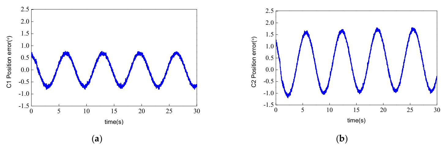
Figure 3, the actual position tracked the input signal well with the proposed controller C1, and C1 had the better performance compared with C2. The position tracking errors of the two controllers in
Figure 4 illustrate that the tracking error of C1 was smaller than that of C2, which means C1 had the better tracking performance than C2. The performance indices are exhibited in
Table 2, demonstrating that C1 can achieve higher tracking accuracy than C2. The states estimation by LESO is shown in
Figure 5. As seen,
and
can be well tracked by
and
, which were estimated by the LESO. The tracking errors of
and
tended to zero quickly, which means the LESO had good convergence rate and stability. The RMSE of
estimation error and
estimation error were 0.00901° and 1.087°, respectively. The system uncertainties and disturbances were compensated by the LESO, so that C1 had a better control performance than that of C2, with a relative poor robustness against the unknown dynamics. Control input voltage of the proposed controller is exhibited in
Figure 6. As shown, it was bounded.
In order to further verify the control performance of the proposed strategy, the input signal
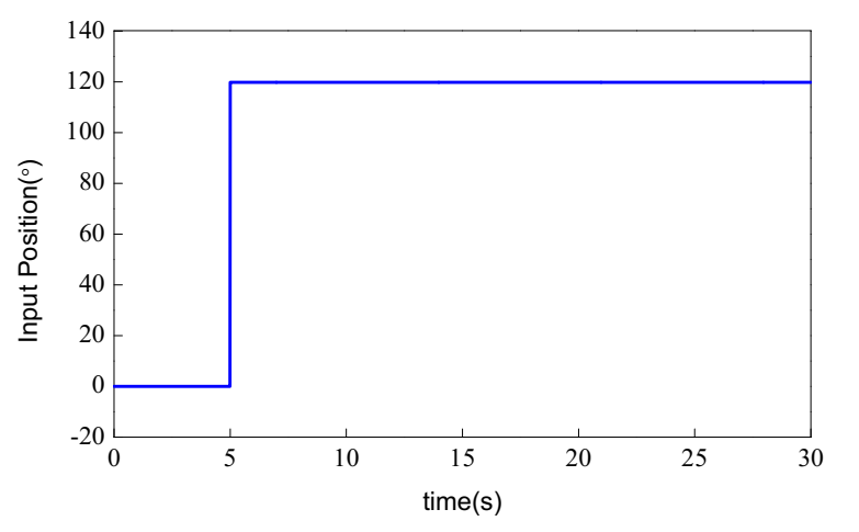
x1d, which was the step signal with maximum angle 120°, is given in
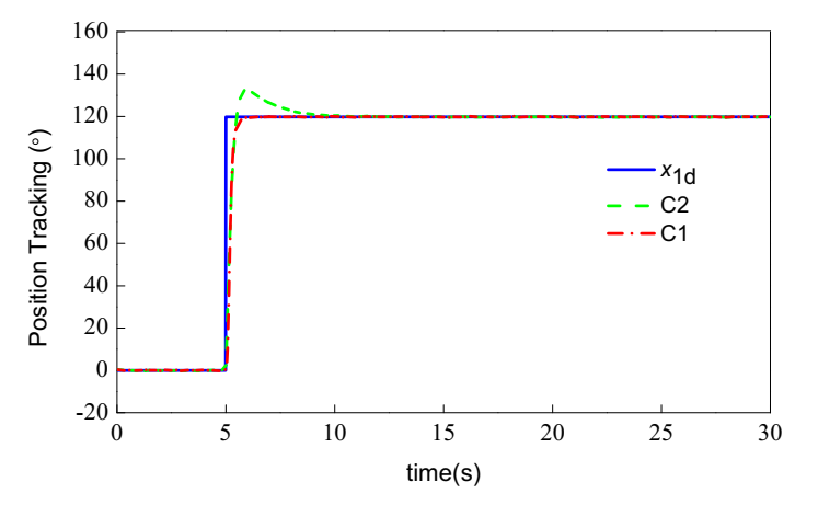
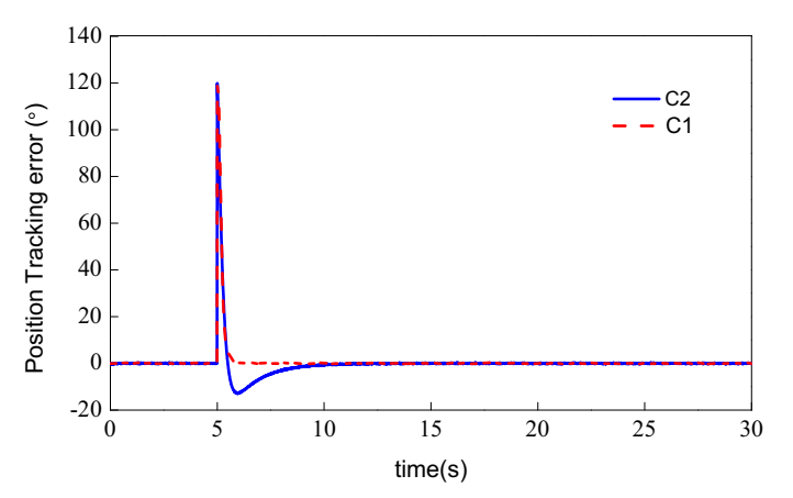
Figure 7. For this motion trajectory, the setpoint jump was not appropriate for most dynamic systems making a step. In order to avoid these undesired characteristics, TD was used to make the output of the plant reasonably follow the input signal. The position tracking of the two controllers is illustrated in
Figure 8. As shown, the setpoint jump of the signal caused overshoot of the tracking signal with the PID controller C2. The proposed controller was applied to avoid the overshoot by using TD, and we obtained that C1 better guaranteed tracking performance in the transient process than C2. The settling time of the system with C1 was 0.63 s, whereas the steady-state error was 0.044°. The tracking error of the two controllers are shown in
Figure 9.
Figure 9 shows that the tracking error of the proposed controller C1 was much smaller than that of C2 in the regulation stage, although the tracking error was large at the step time.

